Advertisement
Quick Links
Advertisement

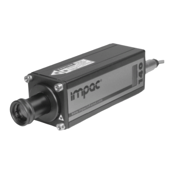
Summary of Contents for LumaSense IMPAC IPE 140
- Page 1 IPE 140 • IPE 140/34 • IPE 140/39 • IPE 140/45...
- Page 12 Water cooling jacket LED large display...
- Page 17 TxD (violet) RxD (black) DGND (red) cable 1 2 3 4 5 6 7 8 9 PC’s side Pyrometer’s side (soldering side female cable connec (soldering side female cable connector) Master Terminator 120 Ohm Pyrometer 1 Pyrometer 2 Pyrometer 32 e.g.
- Page 19 Ø M Ø M Ø M Aperture D...
- Page 20 push / pull release Objective length S...
- Page 21 Screw connection 3 mm hex screw Illuminated Display Setting keys Max. Rear cover pull-out Temperature dis- play or parameter short form Push button short description...
- Page 22 Display of Interface the selected switch interface Test button Test function active (here the analog output is set to 0 … 20 mA) Display which also has to be on an external indication instrument (here temp. range 75 ... 550°C)
- Page 23 Display of the adjusted emissivity...
- Page 32 To ensure consistent document formatting, this page was intentionally left blank.


Need help?
Do you have a question about the IMPAC IPE 140 and is the answer not in the manual?
Questions and answers