Tennant M30 Service Information Manual
Scrubber-sweeper (gas/lpg/diesel)
Hide thumbs
Also See for M30:
- Operator's manual (120 pages) ,
- Service manual (166 pages) ,
- Instruction bulletin (12 pages)
Table of Contents
Advertisement
Quick Links
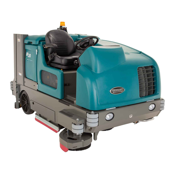
M30
(Gas/LPG/Diesel)
Scrubber- -Sweeper
Service Information Manual
R
The Safe Scrubbing Alternative
R
Hygenic Fully Cleanable Tanks
t
FloorSmart
Integrated Cleaning System
R
ES Extended Scrub System
t
Lower Total Cost of Ownership
North America / International
9003947
Rev. 00 (06-2008)
*9003947*
www.tennantco.com
Advertisement
Table of Contents

Subscribe to Our Youtube Channel
Related Manuals for Tennant M30


Summary of Contents for Tennant M30
- Page 1 (Gas/LPG/Diesel) Scrubber- -Sweeper Service Information Manual The Safe Scrubbing Alternative Hygenic Fully Cleanable Tanks FloorSmart Integrated Cleaning System ES Extended Scrub System Lower Total Cost of Ownership North America / International 9003947 Rev. 00 (06-2008) *9003947* www.tennantco.com...
- Page 2 Thermo- -Sentry, Touch- -N- -Go, 1- -STEP, Clean- -Wedge, Variable Drain Valve, EasyOpen, Grip- -N- -Go, MaxPro@, Dura- -Track, SmartRelease, InstantAccess, Duramer, FaST- -PAK, ES, FloorSmart and ErgoSpace are US registered and unregistered trademarks of Tennant Company. Specifications and parts are subject to change without notice.
-
Page 3: Table Of Contents
....ADJUSTING THE MAIN BRUSH WIDTH ....M30 9003947 (6- -08) - Page 4 ........M30 9003947 (6- -08)
- Page 5 SCRUB VACUUM FAN ON ........M30 9003947 (6- -08)
- Page 6 ........M30 9003947 (6- -08)
-
Page 7: Safety Precautions
CAUTION: LPG engine will run for a few - - Report machine damage or faulty seconds after key is turned off. Apply operation immediately. parking brake before leaving machine. - - Follow mixing and handling instructions on chemical containers. M30 9003947 (6- -08) - Page 8 Keep area well ventilated. - - Use cardboard to locate leaking hydraulic fluid under pressure. - - Use Tennant supplied or approved replacement parts. 7. When loading/unloading machine onto/off truck or trailer: - - Turn off machine.
-
Page 9: General Machine Information
* Call Technical Services if Diagnostic Time Exceeds One Hour With Unknown Cause or Course of Action NOTE: Troubleshooting charts may be shown with optional equipment. The optional equipment may not be specified in these charts. Some machines may not be equipped with all components shown. M30 9003947 (6- -08) -
Page 10: General Machine Dimensions/Capacities
HYDRAULIC SYSTEM System Capacity Fluid Type Hydraulic reservoir 38 L (10 gal) TENNANT part no. 65869 -- above 7_ C (45_ F) TENNANT part no. 65870 -- below 7_ C (45_ F) Hydraulic total 45 L (12 gal) STEERING Type... -
Page 11: Power Type
Parking brake Utilize service brakes, cable actuated TIRES Location Type Size Front (1) Solid 150 mm x 460 mm (6 in x 18 in) Rear (2) Solid 127 mm x 460 mm (5 in x 18 in) M30 9003947 (6- -08) -
Page 12: Fast System
5.2 CC/Minute (0.17 Liquid Ounces/Minute) MACHINE DIMENSIONS Rear Squeegee 1500 mm (59 in) 1475 mm (58 in) Frame 2745 mm (roller to roller) (108 in) 1475 mm (58 in) Width (with side brush) 1625 mm (64 in) 1014751 M30 9003947 (6- -08) -
Page 13: Component Locator (1 Of 8)
5. Engine Indicator lights (Charging, Oil Pressure, Check Engine, Glow Plugs) 6. Ignition switch (S--1) 7. Horn Switch (S--22) 8. Audible Alarm 9. Hopper door open / close switch (S--13) 10. Hopper raise / lower switch (S--5) M30 9003947 (6- -08) - Page 14 9. Solution decrease button (- -) 10.Brush pressure increase button (+) 11. Brush pressure decrease button (- -) 12.Filter shaker button 13.Sweep vacuum fan button 14.Side brush button (option) 15. Engine speed button 16.Supervisor control buttons M30 9003947 (6- -08)
- Page 15 5. Low LPG Fuel Pressure Switch (S--8) 13. Pressure Washer Hydraulic Valve 6. LPG Fuel Tank 14. Spray Nozzle Hose 7. Hydraulic Oil Temperature Sensor (S--20) 15. FaST System Components 8. Fuel Tank 16. FaST Water Pump M30 9003947 (6- -08)
- Page 16 10. Sweeping Vacuum Fan Motor 11. Scrubbing Vacuum Fan Motor 25. Steering Cylinder 12. Main Hydraulic Valve Manifold 26. Side Brush Motor 13. Electronic Pressure Regulator (LPG only) 27. Side Brush Solution Valve (SOL--7) 14. Fuel Filter (LPG only) M30 9003947 (6- -08)
- Page 17 3. Side Brush Motor 9. ES Pump 10. Solution Tank Full Switch (S--14) 4. Left Side Squeegee Lift Cylinder 5. Main Brush Motor (Rear) 11. Solution Tank 6. Right Side Squeegee Lift Cylinder 12. Solution Tank Empty Switch (S--19) M30 9003947 (6- -08)
- Page 18 (page 6 of 8) FRONT FRONT 1. Propel Motor 2. Sweeping Vacuum Fan Motor 3. Scrubbing Vacuum Fan Motor 4. Fuel Tank (LPG Shown) 5. Hydraulic Oil Reservoir 6. Scrub Head Lift Cylinder 7. Scrub Head Lift Assist Spring M30 9003947 (6- -08)
- Page 19 M30 SERVICE INFORMATION General Machine Information Component Locator (page 7 of 8) Main Hydraulic Valve Manifold SV14 SV13 SV15 M30 9003947 (6- -08)
- Page 20 General Machine Information M30 SERVICE INFORMATION Component Locator (page 8 of 8) Side Brush Valve Manifold SV10 SV11 SV12 M30 9003947 (6- -08)
-
Page 21: Maintenance & Repair
* Call Technical Services if Diagnostic Time Exceeds One Hour With Unknown Cause or Course of Action NOTE: Troubleshooting charts may be shown with optional equipment. The optional equipment may not be specified in these charts. Some machines may not be equipped with all components shown. M30 9003947 (6- -08) -
Page 22: Maintenance
Maintenance & Repair M30 SERVICE INFORMATION MAINTENANCE M30 9003947 (6- -08) -
Page 23: Maintenance Chart
Change oil and filter Engine Drain oil from electronic pressure regulator (EPR) (LPG only) 13, 19 Tires Check for damage Rear squeegee casters Lubricate Rear squeegee Check leveling Scrub head skirt Check for damage or wear M30 9003947 (6- -08) - Page 24 . . . Water and ethylene glycol anti-freeze, --34_ C (--30_ F) . . . Special lubricant, Lubriplate EMB grease (Tennant part number 01433--1) NOTE: More frequent maintenance intervals may be required in extremely dusty conditions. M30 9003947 (6- -08)
-
Page 25: Lubrication
LPG engines is 3.5 L (3.7 qt) with oil filter. The engine oil capacity is 6 L (6.35 qt) with oil filter. SQUEEGEE CASTER BEARINGS Lubricate the squeegee caster bearings after every 100 hours of operation. M30 9003947 (6- -08) -
Page 26: Hopper Lift Arm Pivots
HOPPER DOOR PIVOTS Lubricate the hopper door pivots after every 200 On the other side of the machine the torque tube hours of operation. grease fittings are located beneath the propel pump. M30 9003947 (6- -08) -
Page 27: Hydraulics
Tennant hydraulic fluid is specially selected to meet reservoir or operate the machine with a low level the needs of Tennant machines. There are two fluids available for different temperature ranges: of hydraulic fluid in the reservoir. Damage to the machine hydraulic system may result. -
Page 28: Hydraulic Hoses
Serious infection or reaction can occur if proper medical treatment is not given immediately. Contact a mechanic or supervisor if a leak is GAS/LPG discovered. DIESEL Flush the radiator and the cooling system after every 800 hours of operation. M30 9003947 (6- -08) -
Page 29: Air Filter
FOR SAFETY: When servicing machine, wear eye and ear protection when using pressurized air or water. AIR FILTER Replace the air filter after every 400 hours of operation. GAS/LPG GAS/LPG DIESEL DIESEL M30 9003947 (6- -08) -
Page 30: Fuel Filter (Lpg)
FOR SAFETY: When servicing machine, keep FOR SAFETY: When servicing machine, keep flames and sparks away from fuel system service flames and sparks away from fuel system service area. Keep area well ventilated. area. Keep area well ventilated. M30 9003947 (6- -08) -
Page 31: Fuel Lines (Diesel)
Air in the fuel prevents smooth engine operation. This fuel system however is self-priming. The return line comes from the top of the injector that allows the air to escape through the return line. M30 9003947 (6- -08) -
Page 32: Battery
Refer to the diagram below for locations of the fuses and relays on the relay panel. The M10 relay for the optional spray nozzle is located behind the battery. M30 9003947 (6- -08) -
Page 33: Engine Harness Fuses And Relays
12 VDC, 40 A Horn amperage. 12 VDC, 40 A Shutdown 12 VDC, 40 A Starter 12 VDC, 40 A Not Used 12 VDC, 40 A Not Used 12 VDC. 40 A Spray Wand (Separate Relay) M30 9003947 (6- -08) -
Page 34: Cleaning The Hopper Dust Filter
If there is a fire in the hopper, the Thermo--Sentry stops the vacuum fan and cuts off the air flow. The Thermo--Sentry automatically resets after cooling down. M30 9003947 (6- -08) - Page 35 5. Pull the brushes out from the scrub head. 8. Reinstall the brush idler plates. 9. Close the inner and outer brush doors. 10. Check and adjust the brush pattern if needed. Refer to CHECKING THE MAIN BRUSH PATTERN. M30 9003947 (6- -08)
-
Page 36: Checking The Main Brush Pattern
6. Observe the brush patterns. If the brush pattern is the same width across the entire length of each brush and both brushes are the same width, no adjustment is necessary. 10653 10355 M30 9003947 (6- -08) -
Page 37: Adjusting The Main Brush Taper
3. Tighten the mounting bolts. 4. Recheck the pattern. Readjust if necessary. 2. Recheck the pattern. Readjust if necessary. M30 9003947 (6- -08) -
Page 38: Side Brush (Option)
4. Remove the side brush from underneath the side brush assembly. 5. Place the new side brush underneath the side brush assembly and lift the side brush up onto the side brush hub until the brush locks onto the hub. M30 9003947 (6- -08) -
Page 39: Fast System
5. Slide the FaST--PAK carton into the FaST--PAK bracket. 6. Connect the FaST supply hose to the FaST--PAK hose connector. 7. Scrub with the FaST system for a few minutes to allow the detergent to reach maximum foaming. M30 9003947 (6- -08) -
Page 40: Squeegee Blades
7. Remove the rear squeegee. 3. Remove both mounting knobs from the rear squeegee assembly. 4. Turn on the machine, raise the scrub head, and turn off the machine. 5. Remove the rear squeegee assembly from the machine. M30 9003947 (6- -08) - Page 41 13. Install the new front squeegee blade or rotate the existing blade to the new edge. Be sure the holes in the squeegee blade are hooked onto the tabs. 10. Tighten the rear retaining band tension latch. M30 9003947 (6- -08)
-
Page 42: Replacing Or Rotating The Side Squeegee Blades
17. Check and adjust the rear squeegee if necessary. Refer to ADJUSTING THE REAR SQUEEGEE BLADE DEFLECTION and LEVELING THE REAR SQUEEGEE sections of this manual. 4. Remove the retaining band from the side squeegee assembly. M30 9003947 (6- -08) -
Page 43: Replacing The Side Brush Squeegee Blade (Option)
2. Pull the pin from the squeegee bumper and open the squeegee bumper. 7. Reattach the side squeegee retaining band to the side squeegee assembly. M30 9003947 (6- -08) -
Page 44: Leveling The Rear Squeegee
5. Drive the machine forward with the squeegee down to recheck the squeegee blade deflection if adjustments were made. 6. Readjust the squeegee blade deflection if necessary. M30 9003947 (6- -08) -
Page 45: Adjusting The Rear Squeegee Blade Deflection
12 mm (0.50 in) for scrubbing smooth floors squeegee blade deflection after adjustments are and 15 mm (0.62 in) for rough floors. made. 5. Readjust the squeegee blade deflection if 12 mm necessary. (0.50 in) M30 9003947 (6- -08) -
Page 46: Skirts And Seals
The skirts should be between 0 to 6 mm (0 to 0.25 in) from the floor when the scrub head is down. RECOVERY TANK SEAL Check the recovery tank cover seal for damage and wear daily. M30 9003947 (6- -08) -
Page 47: Brakes And Tires
FRONT WHEEL Torque the front wheel nuts twice in the pattern shown to 122 to 149 Nm (90 to 110 ft lb) after the first 50 hours of operation, and after every 800 hours there after. M30 9003947 (6- -08) -
Page 48: Pushing, Towing, And Transporting The Machine
AND is 380 mm (15 in) or less from the ground. 4. To winch the machine onto the truck or trailer, attach the winching chains to the holes in the rear jacking brackets behind the rear tires. M30 9003947 (6- -08) - Page 49 FOR SAFETY: When unloading machine off truck or trailer, use winch. Do not drive the machine off the truck or trailer unless the loading surface is horizontal AND 380 mm (15 in) or less from the ground. M30 9003947 (6- -08)
-
Page 50: Machine Jacking
FOR SAFETY: When servicing machine, block temperatures requires special procedures. Consult a machine tires before jacking machine up. Use a TENNANT representative for more information. hoist or jack that will support the weight of the machine. Jack machine up at designated locations only. -
Page 51: Electrical
* Call Technical Services if Diagnostic Time Exceeds One Hour With Unknown Cause or Course of Action NOTE: Troubleshooting charts may be shown with optional equipment. The optional equipment may not be specified in these charts. Some machines may not be equipped with all components shown. M30 9003947 (6- -08) -
Page 52: Electrical Schematic (1 Of 8)
Electrical Troubleshooting M30 SERVICE INFORMATION Electrical Schematic (1 of 8) M30 9003947 (6- -08) - Page 53 M30 SERVICE INFORMATION Electrical Troubleshooting Electrical Schematic (2 of 8) M30 9003947 (6- -08)
- Page 54 Electrical Troubleshooting M30 SERVICE INFORMATION Electrical Schematic (3 of 8) M30 9003947 (6- -08)
- Page 55 M30 SERVICE INFORMATION Electrical Troubleshooting Electrical Schematic (4 of 8) M30 9003947 (6- -08)
- Page 56 Electrical Troubleshooting M30 SERVICE INFORMATION Electrical Schematic (5 of 8) M30 9003947 (6- -08)
- Page 57 M30 SERVICE INFORMATION Electrical Troubleshooting Electrical Schematic (6 of 8) M30 9003947 (6- -08)
- Page 58 Electrical Troubleshooting M30 SERVICE INFORMATION Electrical Schematic (7 of 8) M30 9003947 (6- -08)
- Page 59 M30 SERVICE INFORMATION Electrical Troubleshooting Electrical Schematic (8 of 8) M30 9003947 (6- -08)
-
Page 60: Gas Engine Harness Electrical Schematic (1 Of 2)
Electrical Troubleshooting M30 SERVICE INFORMATION Gas Engine Harness Electrical Schematic (1 of 2) M30 9003947 (6- -08) - Page 61 M30 SERVICE INFORMATION Electrical Troubleshooting Gas Engine Harness Electrical Schematic (2 of 2) M30 9003947 (6- -08)
-
Page 62: Lpg Engine Harness Electrical Schematic (1 Of 2)
Electrical Troubleshooting M30 SERVICE INFORMATION LPG Engine Harness Electrical Schematic (1 of 2) M30 9003947 (6- -08) - Page 63 M30 SERVICE INFORMATION Electrical Troubleshooting LPG Engine Harness Electrical Schematic (2 of 2) M30 9003947 (6- -08)
-
Page 64: Main Wire Harness Diagram (1 Of 7)
Electrical Troubleshooting M30 SERVICE INFORMATION Main Wire Harness Diagram (1 of 7) M30 9003947 (6- -08) - Page 65 M30 SERVICE INFORMATION Electrical Troubleshooting Main Wire Harness Diagram (2 of 7) M30 9003947 (6- -08)
- Page 66 Electrical Troubleshooting M30 SERVICE INFORMATION Main Wire Harness Diagram (3 of 7) M30 9003947 (6- -08)
- Page 67 M30 SERVICE INFORMATION Electrical Troubleshooting Main Wire Harness Diagram (4 of 7) M30 9003947 (6- -08)
- Page 68 Electrical Troubleshooting M30 SERVICE INFORMATION Main Wire Harness Diagram (5 of 7) M30 9003947 (6- -08)
- Page 69 M30 SERVICE INFORMATION Electrical Troubleshooting Main Wire Harness Diagram (6 of 7) M30 9003947 (6- -08)
- Page 70 Electrical Troubleshooting M30 SERVICE INFORMATION Main Wire Harness Diagram (7 of 7) M30 9003947 (6- -08)
-
Page 71: Hopper Harness Diagram
M30 SERVICE INFORMATION Electrical Troubleshooting Hopper Harness Diagram M30 9003947 (6- -08) -
Page 72: Hopper Cover Harness Diagram
Electrical Troubleshooting M30 SERVICE INFORMATION Hopper Cover Harness Diagram M30 9003947 (6- -08) -
Page 73: Diesel Engine Wire Harness Diagram (1 Of 2)
M30 SERVICE INFORMATION Electrical Troubleshooting Diesel Engine Wire Harness Diagram (1 of 2) M30 9003947 (6- -08) - Page 74 Electrical Troubleshooting M30 SERVICE INFORMATION Diesel Engine Wire Harness Diagram (2 of 2) M30 9003947 (6- -08)
-
Page 75: Fast Wire Harness Diagram
M30 SERVICE INFORMATION Electrical Troubleshooting FaST Wire Harness Diagram M30 9003947 (6- -08) -
Page 76: Electrical Symbols & Abbreviations
SW – Switch Example of Wiring Numbers & Colors: Wiring Color Codes (Unless otherwise marked) Right Most Digit Color of Wire of Wire Number Pink Brown Orange 1 RED 13 BLK Yellow Green Blue Purple Gray White M30 9003947 (6- -08) -
Page 77: Touch Panel Detail
Solution & detergent increase button (+) Solution & detergent decrease button (-) Brush pressure increase button (+) Brush pressure decrease button (-) Filter shaker button Sweep vacuum fan button Side brush button Engine speed button Supervisor control buttons M30 9003947 (6- -08) -
Page 78: Touch Panel Leds
Scrubbing Vacuum Fan ON & Squeegee System ON Indicator 1-STEP Scrub ON Indicator Brush Pressure Indicators (1 LED=Low, 2 LED’s=Medium, 3 LED’s=High) Solution Volume Indicators (1 LED=Low, 2 LED’s=Medium, 3 LED’s=High) ES (Extended Scrub) System ON Indicator M30 9003947 (6- -08) -
Page 79: Key Switch
RUN POSITION START POSITION Spring loaded-Returns to “RUN" unless held SWITCH TERMINAL MARKING GLOW PLUG NO CONNECTIONS START “ . “ Indicates a common connection Common connections in various switch positions should be less than 1 M30 9003947 (6- -08) -
Page 80: Key Off Power Distribution
Battery voltage is always present, even with Key OFF Yellow Green Blue Pin P2-3 supplies power to the on-board clock only. Purple Disconnecting battery, removing Fuse 10, or removing connector Gray P2 from Control Board will require the clock to be reset. White M30 9003947 (6- -08) -
Page 81: Key On Power Distribution
(Unless otherwise marked) Right Most Digit Color of Wire of Wire Number 13/BLK 13/BLK Pink 1/RED Brown TO FUSES AUX. 3 2,3, & 11 Orange RELAY Yellow Green 1/RED TO FUSES Blue 13 & 14 Purple Gray White M30 9003947 (6- -08) -
Page 82: Main Brushes On
Panel LED indicators for Brush down pressure Pink Brown SV-2 is controlled by PWM; A higher duty cycle Orange (more Brush Pressure LED’s lit on Touch Yellow Panel) will result in more brush down pressure Green Blue Purple Gray White M30 9003947 (6- -08) -
Page 83: Side Brush On
Wire Number Pink Brown SV-10 is controlled by PWM; A higher duty cycle Orange (more Brush Pressure LED’s lit on Touch Yellow Panel) will result in more brush down pressure Green Blue Purple Gray White M30 9003947 (6- -08) -
Page 84: Scrub Vacuum Fan On & Squeegees Down
Right Most Digit Color of Wire of Wire Number Pink Brown Orange Any condition that cancels the scrub functions will also Yellow turn OFF the scrub vacuum fan and raise squeegees. Green Blue Purple Gray White M30 9003947 (6- -08) -
Page 85: Sweep Vacuum Fan On
Sentry Switch closes (above of Wire Number 140°F in hopper), all sweep functions are cancelled. Pink Brown A short shaker cycle is Orange automatically performed Yellow each time the Sweep Green Vacuum is turned OFF Blue Purple Gray White M30 9003947 (6- -08) -
Page 86: Hopper Lift
Wiring Color Codes (Unless otherwise marked) Right Most Digit Component Max Amp Draw Color of Wire of Wire Number SV-7 1.7 A Pink SV-13 1.7 A Brown SV-14 1.7 A Orange Yellow Green Blue Purple Gray White M30 9003947 (6- -08) -
Page 87: Hopper Lower
Wiring Color Codes (Unless otherwise marked) Right Most Digit Color of Wire Component Max Amp Draw of Wire Number SV-7 1.7 A Pink SV-13 1.7 A Brown Orange SV-14 1.7 A Yellow Green Blue Purple Gray White M30 9003947 (6- -08) -
Page 88: Hopper Door Open
HIGH engine speed Wiring Color Codes (Unless otherwise marked) Right Most Digit Color of Wire of Wire Number Pink Brown Orange Yellow Green Blue Purple Gray White M30 9003947 (6- -08) -
Page 89: Hopper Door Close
HIGH engine speed Wiring Color Codes (Unless otherwise marked) Right Most Digit Color of Wire of Wire Number Pink Brown Orange Yellow Green Blue Purple Gray White M30 9003947 (6- -08) -
Page 90: Shaker Motor On
Sentry Switch closes (above of Wire Number 140°F in hopper), all sweep functions are cancelled. Pink Brown A short shaker cycle is Orange automatically performed Yellow each time the Sweep Green Vacuum is turned OFF Blue Purple Gray White M30 9003947 (6- -08) -
Page 91: Forward Propel
Low Engine Speed LED to adjust the arm closest to the rear of machine (reverse adjustment). FRONT Wiring Color Codes (Unless otherwise marked) Right Most Digit Color of Wire of Wire Number Pink REVERSE Brown ADJUSTMENT Orange Yellow Green Blue Purple Gray White M30 9003947 (6- -08) -
Page 92: Reverse Propel
TAIL LIGHT 13/BLK (Unless otherwise marked) Right Most Digit Color of Wire of Wire Number Pink See Forward Propel page for Brown information on adjusting Orange Propel Pedal Position Sensor Yellow Green Blue Purple Gray White M30 9003947 (6- -08) -
Page 93: Hydraulic Oil Temperature & Filter Clogged Sensors
5 minutes to allow the hydraulic oil to warm up Wiring Color Codes (Unless otherwise marked) Right Most Digit Color of Wire of Wire Number Pink Brown Orange Yellow Green Blue Purple Gray White M30 9003947 (6- -08) -
Page 94: Solution & Recovery Tank Level Switches
Wiring Color Codes (Unless otherwise marked) Right Most Digit Color of Wire of Wire Number The Float Switches must be closed for 5 seconds before any output is affected Pink Brown Orange Yellow Green Blue Purple Gray White M30 9003947 (6- -08) -
Page 95: Conventional Main & Side Brush Solution Valves
Wiring Color Codes (Unless otherwise marked) Right Most Digit Color of Wire of Wire Number Pink Brown Orange Yellow Green Blue Low Solution Medium Solution High Solution Purple Gray White M30 9003947 (6- -08) -
Page 96: Fast System On (Low Flow)
Battery Negative is input to the pump on Wire 79/White, High Flow is selected. Pink Brown Orange Yellow Green One or two Solution LED’s Blue lit selects Low FaST output Purple Gray Low FaST Low FaST High FaST White M30 9003947 (6- -08) -
Page 97: Fast System On (High Flow)
Battery Negative is input to the pump on Wire 79/White, High Flow is selected. Pink Brown Orange Yellow Green One or two Solution LED’s Blue lit selects Low FaST output Purple Gray Low FaST Low FaST High FaST White M30 9003947 (6- -08) -
Page 98: Extended Scrub (Es) System
LED’s lit on Touch Panel) will result in more detergent & solution applied to floor Pink Brown Orange Yellow Green Blue Purple Gray Low Water and Medium Water and High Water and Detergent Pump OFF Detergent Pump LOW Detergent Pump HIGH White M30 9003947 (6- -08) -
Page 99: Auto Fill Solenoids
Half Full Switch OPEN (tank less than half full) to Pink activate Recovery Tank Auto Fill Valve (SOL-2) Brown Orange Yellow Green The Float Switches must be closed for Blue 5 seconds before any output is affected Purple Gray White M30 9003947 (6- -08) -
Page 100: Starting System On (Gas/Lpg)
RELAY 13/BLK 13/BLK TO FUSES 1, 9, & 12 KEY SWITCH START Wiring Color Codes (Unless otherwise marked) Right Most Digit Color of Wire of Wire Number Pink Brown Orange Yellow Green Blue Purple Gray White M30 9003947 (6- -08) -
Page 101: Starting System On (Diesel)
P1/J2 Brown SWITCHED BATTERY POSITIVE TO FUEL PUMP RELAY FROM SHUTDOWN RELAY M6C M10 & GOVERNOR Orange Yellow Green ENGINE HARNESS CONNECTOR Blue Purple The Starter Timer Module creates Gray a delay between start attempts White M30 9003947 (6- -08) -
Page 102: Shutdown Relay -- Normal Machine Operation (Gas/Lpg)
The Shutdown system is used to turn OFF the Yellow engine under certain conditions on machines Green with certain optional equipment Blue Purple When control board turns ON M6A, Gray the engine ECM loses power, and White engine shuts OFF M30 9003947 (6- -08) -
Page 103: Shutdown Relay -- Normal Machine Operation (Diesel)
The Shutdown system is used to turn OFF the Yellow engine under certain conditions on machines Green with certain optional equipment Blue Purple When control board turns ON M6A, Gray the fuel pump loses power, and White engine shuts OFF M30 9003947 (6- -08) -
Page 104: Shutdown Relay -- Shutdown Mode (Gas/Lpg)
The Shutdown system is used to turn OFF the Yellow engine under certain conditions on machines Green with certain optional equipment Blue Purple When control board turns ON M6A, Gray the engine ECM loses power, and White engine shuts OFF M30 9003947 (6- -08) -
Page 105: Shutdown Relay -- Shutdown Mode (Diesel)
The Shutdown system is used to turn OFF the Yellow engine under certain conditions on machines Green with certain optional equipment Blue Purple When control board turns ON M6A, Gray the engine ECM loses power, and White engine shuts OFF M30 9003947 (6- -08) -
Page 106: Engine Oil Pressure, Temperature, & Mil Systems (Gas/Lpg)98
Wire Number BATTERY POSITIVE Pink FROM FUSE 1 Brown Refer to the Engine Orange Schematics Yellow MIL SIGNAL Green GREEN/YELLOW FROM ECM Blue PIN 80 ENGINE MIL (CHECK Purple HARNESS ENGINE LAMP) Gray CONNECTOR White M30 9003947 (6- -08) -
Page 107: Engine Oil Pressure & Temperature Systems (Diesel)
NEGATIVE Color of Wire Touch Panel / of Wire Number Control Board HIGH ENGINE TEMPERATURE Pink SWITCH 13/BLK Brown PIN P1-18 Orange Yellow Green Blue OPEN = BELOW 220°F CLOSED = ABOVE 220°F Purple Gray White M30 9003947 (6- -08) -
Page 108: Fuel Level Sensors
OPEN = MORE THAN 70 PSI CLOSED = 70 PSI OR LOWER Wiring Color Codes (Unless otherwise marked) Right Most Digit Color of Wire of Wire Number Pink Brown Orange Yellow Green Blue Purple Gray White M30 9003947 (6- -08) -
Page 109: Fuel Pump & Engine Speed Control (Gas/Lpg)
Wire Number ENGINE SPEED Pink CHART Brown Orange Engine RPM 1350 (+/- 50) 2700 (+/- 50) Yellow Voltage Speed “A” 5 VDC 0 VDC Green Blue Voltage Speed “B” 0 VDC 0 VDC Purple Gray White M30 9003947 (6- -08) -
Page 110: Fuel Pump (Diesel)
Right Most Digit Color of Wire ENGINE OIL of Wire Number PRESSURE SWITCH Pink B & C CLOSED = LOW OIL PRESSURE Brown B & A CLOSED = OIL PRESSURE OK Orange Yellow Green Blue Purple Gray White M30 9003947 (6- -08) -
Page 111: Engine Speed Control (Diesel)
INPUT – Engine Speed Sensor Orange INPUT – Engine Speed Sensor Yellow OUTPUT – Throttle Actuator (PWM) Green Blue OUTPUT – Throttle Actuator Purple INPUT – Engine Speed Selection “A” Gray INPUT – Engine Speed Selection “B” White M30 9003947 (6- -08) -
Page 112: Glow Plugs On (Diesel)
(Unless otherwise marked) Right Most Digit Color of Wire of Wire Number Pink Brown The Glow Plugs are ON only when ignition Orange switch is in the “Glow Plug” or “Start” position Yellow Green Blue Purple Gray White M30 9003947 (6- -08) -
Page 113: Control Board Connectors
Scrub Vacuum Fan Valve P2-29 brown output Audible Alarm P2-30 unused P2-31 orange output SV-13 Hopper Down Solenoid Valve P2-32 unused P2-33 black ground Unswitched Battery Negative P2-34 black ground Unswitched Battery Negative P2-35 black ground Unswitched Battery Negative M30 9003947 (6- -08) -
Page 114: Fault Indicators
High Hydraulic Indicates excessive hydraulic F9: HIGH HYD TEMP Temperature temperature Low fuel indicator (blinking lowest fuel Low Fuel F10: LOW FUEL gauge block). Squeegee Indicates squeegee may have broken Disconnected F11: OPEN SCB VAC free. (Option) M30 9003947 (6- -08) -
Page 115: Condition & Warning Indicators
ON the ES FaST option. or FaST system. Side Brush button is The machine is NOT C6: NO SIDE BRUSH activated alone without programmed to operate with 1-STEP Sweep/Scrub. only the side brush ON. M30 9003947 (6- -08) -
Page 116: Configuration Modes (1 Of 3)
(Low/Medium/High). 4) Press “0/1” button to increase the down pressure OR press “8/9” button to decrease the down pressure. 5) Press 1-STEP Sweep button again or turn key switch OFF to save new down pressure settings. M30 9003947 (6- -08) - Page 117 FaST system 2) Press “2/3” button until “FAST MODE” system, and disables the ES system. (also disables is displayed. the ES 3) Press “0/1” button to enable the FaST system) system. “DONE” is displayed on LCD screen. M30 9003947 (6- -08)
- Page 118 3) Press “0/1” button to observe Note: There will be NO solution delivery to “SIDE_SWEEP&SCRUB” or Side Brush when in Scrub mode if “SIDE_SWEEP_ONLY” “SIDE_SWEEP_ONLY” is selected. 4) Press 1-STEP Scrub button to toggle between modes. M30 9003947 (6- -08)
-
Page 119: Diagnostic Modes
Hopper Door Close Scrub Pressure Low LED Solution Tank Empty Solution Level High LED Solution Tank Full Solution Tank Medium LED Recovery Tank Full Solution Tank Low LED Recovery Tank Half Full Red warning LED Open Scrub Vacuum M30 9003947 (6- -08) - Page 120 Electrical Troubleshooting M30 SERVICE INFORMATION M30 9003947 (6- -08)
-
Page 121: Hydraulic
* Maintain Normal Main Brush Pressure as Listed in Operator’s Manual NOTE: Troubleshooting charts may be shown with optional equipment. The optional equipment may not be specified in these charts. Some machines may not be equipped with all components shown. M30 9003947 (6- -08) -
Page 122: Hydraulic Pump Flow Rates
Switch Load Sens e Throttle Valve Motor (Com bus tion) Volts Typical Hydraulic Manifold Port Markings Hydraulic Cylinder Connection Hydraulic Motor Connection Test Port Pump Connection Load Sense Port R or T Return Port (To Tank) M30 9003947 (6- -08) -
Page 123: Hydraulic Schematic (1 Of 2)
M30 SERVICE INFORMATION Hydraulic Troubleshooting Hydraulic Schematic (1 of 2) M30 9003947 (6- -08) - Page 124 Hydraulic Troubleshooting M30 SERVICE INFORMATION Hydraulic Schematic (2 of 2) M30 9003947 (6- -08)
-
Page 125: Steering & Propel Hydraulic Hose Diagram
M30 SERVICE INFORMATION Hydraulic Troubleshooting Steering & Propel Hydraulic Hose Diagram Reservoir Steering Valve Aux Pump Propel Pump Steer Cylinder Wheel Drive Motor M30 9003947 (6- -08) -
Page 126: Pump & Vacuum Fan Hydraulic Hose Diagram
Hydraulic Troubleshooting M30 SERVICE INFORMATION Pump & Vacuum Fan Hydraulic Hose Diagram Vac Fan Motor (Scrub) Reservoir Vac Fan Motor (Sweep) Aux Pump Propel Pump Cooler M30 9003947 (6- -08) -
Page 127: Brush & Hopper Hydraulic Hose Diagram
M30 SERVICE INFORMATION Hydraulic Troubleshooting Brush & Hopper Hydraulic Hose Diagram RH Hopper Lift Cylinder Scrub Valve LH Hopper Lift Cylinder Hopper Dump Door Cylinder Main Brush Brush LIft Motor Cylinder (Front) Main Brush Motor (Rear) M30 9003947 (6- -08) -
Page 128: Squeegee Lift Hydraulic Hose Diagram
Hydraulic Troubleshooting M30 SERVICE INFORMATION Squeegee Lift Hydraulic Hose Diagram Scrub Valve Rear Squeegee Lift Cylinder Right Side Squeegee Lift Cylinder Left Side Squeegee Lift Cylinder M30 9003947 (6- -08) -
Page 129: Hydraulic Cooler & Tubes Hose Diagram
M30 SERVICE INFORMATION Hydraulic Troubleshooting Hydraulic Cooler & Tubes Hose Diagram M30 9003947 (6- -08) -
Page 130: Side Brush Hydraulic Hose Diagram
Hydraulic Troubleshooting M30 SERVICE INFORMATION Side Brush Hydraulic Hose Diagram Vac Fan Motor Sweep Reservoir Side Brush Lift cylinder Side Brush Side Brush Motor Pivot cylinder M30 9003947 (6- -08) -
Page 131: Pressure Washer Motor Hydraulic Hose Diagram
M30 SERVICE INFORMATION Hydraulic Troubleshooting Pressure Washer Motor Hydraulic Hose Diagram Vac Fan Motor (Sweep) With Side Brush With Out Side Brush M30 9003947 (6- -08) -
Page 132: Operating Matrix
Hydraulic Troubleshooting M30 SERVICE INFORMATION Operating Matrix M30 9003947 (6- -08) -
Page 133: Hydraulic Symbols
Orifice Reservoir Heat Exchanger With Bypass EXAMPLES Non-Energized Energized Coils Coils SV14 Arrow indicates a PWM (Pulse Width Modulated) valve SV19 SV25 Circled envelope is valve position for indicated Indicates Energized Solenoid Valve Coil hydraulic circuit M30 9003947 (6- -08) -
Page 134: Scrub/Sweep Head Lower
(5 – 7.5 bar) SCRUB HEAD ACTUATOR NOTE SPRING ASSIST The “# Brush Pressure LEDs ON” ENGINE are the Touch Panel LED indicators for Brush down pressure FILTER COOLER 3 PSI SCREEN (20.7 kPa) 35 PSI (2.4 BAR) M30 9003947 (6- -08) -
Page 135: Scrub/Sweep Head Lift
Case Drain Line 0.140 in (3.55 mm) 2500 PSI (172.4 BAR) Scrub Head ORIFICE Actuator 0.040 in (1.0 mm) SCRUB HEAD ACTUATOR NOTE SPRING ASSIST ENGINE FILTER COOLER 3 PSI SCREEN (20.7 kPa) 35 PSI (2.4 BAR) M30 9003947 (6- -08) -
Page 136: Squeegees Lower
LEFT RIGHT REAR SQUEEGEE SQUEEGEE SQUEEGEE ACTUATOR ACTUATOR ACTUATOR ORIFICE ORIFICE ORIFICE 0.031 in 0.031 in 0.036 in (0.79 mm) (0.79 mm) (0.91 mm) ENGINE FILTER COOLER 3 PSI SCREEN (20.7 kPa) 35 PSI (2.4 BAR) M30 9003947 (6- -08) -
Page 137: Squeegees Lift
LEFT RIGHT REAR SQUEEGEE SQUEEGEE SQUEEGEE ACTUATOR ACTUATOR ACTUATOR ORIFICE ORIFICE ORIFICE 0.031 in 0.031 in 0.036 in (0.79 mm) (0.79 mm) (0.91 mm) ENGINE FILTER COOLER 3 PSI SCREEN (20.7 kPa) 35 PSI (2.4 BAR) M30 9003947 (6- -08) -
Page 138: Main Brushes On
Case Drain Line 2500 PSI (172.4 BAR) 0.140 in (3.55 mm) REAR MAIN FRONT MAIN BRUSH BRUSH MOTOR MOTOR Main Brush Motors speed: ENGINE 460-480 RPM FILTER COOLER 3 PSI SCREEN (20.7 kPa) 35 PSI (2.4 BAR) M30 9003947 (6- -08) -
Page 139: Side Brush On
MANIFOLD SCRUB FAN MOTOR 1800 PSI (124 BAR) 25 PSI (1.7 BAR) SWEEP FAN SIDE BRUSH MOTOR MOTOR ENGINE Side Brush Motor speed: 140-160 RPM COOLER FILTER 3 PSI SCREEN (20.7 kPa) 35 PSI (2.4 BAR) M30 9003947 (6- -08) -
Page 140: Scrub Vacuum Fan On
PRESSURE WASHER MOTOR SIDE BRUSH MANIFOLD SOL1 SCRUB FAN MOTOR 1800 PSI (124 BAR) 25 PSI (1.7 BAR) SWEEP FAN SIDE BRUSH MOTOR MOTOR ENGINE COOLER FILTER 3 PSI SCREEN (20.7 kPa) 35 PSI (2.4 BAR) M30 9003947 (6- -08) -
Page 141: Scrub Vacuum Fan & Side Brush On
(1.7 BAR) SWEEP FAN SIDE BRUSH MOTOR MOTOR ENGINE Side Brush can only be Side Brush Motor speed: operated when Main 140-160 RPM Brushes are ON COOLER FILTER 3 PSI SCREEN (20.7 kPa) 35 PSI (2.4 BAR) M30 9003947 (6- -08) -
Page 142: Sweep Vacuum Fan On
18-24 in/H2O (45-61 cm/H2O) PRESSURE WASHER MOTOR SIDE BRUSH SOL1 MANIFOLD SCRUB FAN MOTOR 1800 25 PSI (124 (1.7 BAR) BAR) SWEEP FAN SIDE BRUSH MOTOR MOTOR ENGINE COOLER FILTER 3 PSI SCREEN (20.7 kPa) 35 PSI (2.4 BAR) M30 9003947 (6- -08) -
Page 143: Sweep Vacuum Fan & Side Brush On
BAR) SWEEP FAN SIDE BRUSH MOTOR MOTOR ENGINE Side Brush can only be Side Brush Motor speed: operated when Main 140-160 RPM Brushes are ON COOLER FILTER 3 PSI SCREEN (20.7 kPa) 35 PSI (2.4 BAR) M30 9003947 (6- -08) -
Page 144: Pressure Washer On
PRESSURE WASHER MOTOR SIDE BRUSH MANIFOLD SOL1 SCRUB FAN MOTOR 1800 PSI (124 BAR) 25 PSI (1.7 BAR) SWEEP FAN SIDE BRUSH MOTOR MOTOR ENGINE COOLER FILTER 3 PSI SCREEN (20.7 kPa) 35 PSI (2.4 BAR) M30 9003947 (6- -08) -
Page 145: Hopper Lift
(3.55 mm) 2500 PSI (172.4 BAR) ORIFICE 0.040 in (1.0 mm) 1100 PSI (75.8 BAR) SV13 SV14 HOPPER LIFT ORIFICES ACTUATORS 0.028 in 0.031 in (0.79 mm) (0.71 mm) ENGINE FILTER COOLER SCREEN 35 PSI (2.4 BAR) M30 9003947 (6- -08) -
Page 146: Hopper Lower
(3.55 mm) 2500 PSI (172.4 BAR) ORIFICE 0.040 in (1.0 mm) 1100 PSI (75.8 BAR) SV13 HOPPER LIFT ORIFICES ACTUATORS 0.028 in 0.031 in (0.79 mm) (0.71 mm) ENGINE SV14 FILTER COOLER SCREEN 35 PSI (2.4 BAR) M30 9003947 (6- -08) -
Page 147: Hopper Door Open
Inactive Pilot Port Line or activated Case Drain Line 0.140 in (3.55 mm) 2500 PSI (172.4 BAR) ORIFICE 0.040 in (1.0 mm) HOPPER DOOR ACTUATOR SV15 0.040 in (1.0 mm) ENGINE FILTER COOLER SCREEN 35 PSI (2.4 BAR) M30 9003947 (6- -08) -
Page 148: Hopper Door Close
Inactive Pilot Port Line or activated Case Drain Line 0.140 in (3.55 mm) 2500 PSI (172.4 BAR) ORIFICE 0.040 in (1.0 mm) SV15 HOPPER DOOR ACTUATOR 0.040 in (1.0 mm) ENGINE FILTER COOLER SCREEN 35 PSI (2.4 BAR) M30 9003947 (6- -08) -
Page 149: Side Brush Lower
(1.0 mm) SIDE BRUSH LIFT ACTUATOR SV10 SV11 PR1A 400 PSI (27.6 BAR) The “# Brush Pressure LEDs ON” ENGINE are the Touch Panel LED indicators for Brush down pressure FILTER COOLER SCREEN 35 PSI (2.4 BAR) M30 9003947 (6- -08) -
Page 150: Side Brush Lift
(3.55 mm) 2500 PSI (172.4 BAR) ORIFICE 0.055 in (1.4 mm) SIDE BRUSH MANIFOLD 0.040 in (1.0 mm) SIDE BRUSH LIFT ACTUATOR SV11 SV10 PR1A 400 PSI (27.6 BAR) ENGINE FILTER COOLER SCREEN 35 PSI (2.4 BAR) M30 9003947 (6- -08) -
Page 151: Side Brush Extend
(3.55 mm) 2500 PSI (172.4 BAR) ORIFICE 0.055 in (1.4 mm) SIDE BRUSH MANIFOLD PR1B 0.040 in 100 PSI (1.0 mm) SIDE BRUSH (6.9 BAR) EXTEND ACTUATOR SV12 ENGINE FILTER COOLER SCREEN 35 PSI (2.4 BAR) M30 9003947 (6- -08) -
Page 152: Side Brush Retract
(3.55 mm) 2500 PSI (172.4 BAR) ORIFICE 0.055 in (1.4 mm) SIDE BRUSH MANIFOLD PR1B 0.040 in 100 PSI (1.0 mm) SIDE BRUSH (6.9 BAR) EXTEND ACTUATOR SV12 ENGINE FILTER COOLER SCREEN 35 PSI (2.4 BAR) M30 9003947 (6- -08) -
Page 153: Hydraulic Solenoid Valve Details
*PWM* Enable Valve Side Brush Motor Sweep Fan Motor Side Brush Lift/Lower Actuator SV13 SV12 SOL1 SV11 SV15 Side Brush Side Brush Hopper Door Pressure Washer Lift/Lower Actuator Extend/Retract Actuator Motor SV14 Actuator Hopper Lift/Lower Actuator M30 9003947 (6- -08) - Page 154 Hydraulic Troubleshooting M30 SERVICE INFORMATION M30 9003947 (6- -08)
-
Page 155: Pressure Washer Pump
* Call Technical Services if Diagnostic Time Exceeds One Hour With Unknown Cause or Course of Action NOTE: Troubleshooting charts may be shown with optional equipment. The optional equipment may not be specified in these charts. Some machines may not be equipped with all components shown. M30 9003947 (6- -08) -
Page 156: Formulas, Conversions
Do not operate gasoline engines in a Do not operate in or around an confined area; always have adequate explosive environment. ventilation. Always wear safety glasses Do not exceed the pump or goggles and appropriate specifications in speed or pressure. clothing. M30 9003947 (6- -08) -
Page 157: Pump Features
Never spray or clean the unit with water disbursement. Failure to follow these warnings Bearing Support: Precision die-cast may result in personal injury or and machined to assure concentricity damage to property. and alignment. M30 9003947 (6- -08) -
Page 158: Installation
6. Install the appropriate water inlet the crankcase. and discharge fittings. Oil Capacity: 15.5 oz. 7. Connect the water supply hose and high-pressure discharge hose/spray gun. 8. Turn on the water supply. M30 9003947 (6- -08) -
Page 159: Pump Service
Winter or Long Time Storage valve. (See Figure Drain all of the water out of the pump. Run a 50% solution of a RV or non-toxic/biodegradable antifreeze Figure 11 through the pump. M30 9003947 (6- -08) - Page 160 Servicing the twist the retainer in Packings/Seals Figure 20 either direction To access the water seals for inspection or replacement, you will first Figure 16 need to remove the head of the pump. M30 9003947 (6- -08)
- Page 161 Install the retainer O-ring. Figure 26) (See Figure 32) Install the high- pressure seal. Place the seal so the open “V” portion is toward the head ring. You Figure 32 Figure 26 need to place the M30 9003947 (6- -08)
- Page 162 Figure 34) Figure 34 the back-up ring is fully Insert the gasket scraper seated). Make sure you fully seat between the copper the plunger. washer and plunger to remove the washer. (See Figure 35) Figure 35 M30 9003947 (6- -08)
- Page 163 (See Figure 44 Figure 45) Torque the head bolt as shown in the tightening sequence diagram. (See Figure Figure 45 46 & 47) (See parts break- down) Figure 46 Figure 47 M30 9003947 (6- -08)
-
Page 164: Adjusting Unloader Valve
221 in/lbs 19 ft/lbs in place with hex wrench, use special tool (AR1560590) Or extended 13mm socket wrench to hand tighten AR1560590 (pos. #3) nut against (pos. #4) black Nut holder for adjusting Gymatic Unloader knob. M30 9003947 (6- -08) -
Page 165: Troubleshooting
1 Clean or replace valves tuates foreign bodies 2 Packing worn 2 Replace packing Low pressure 1 Worn nozzle 1 Replace with nozzle of proper size 2 Belt slippage 2 Tighten or replace with correct belt M30 9003947 (6- -08) - Page 166 Loud knocking noise 1 Cavitation or sucking air 1 Check water supply is turned on in pump 2 Pulley loose on crankshaft 2 Check key and tighten set screw 3 Broken or worn bearing 3 Replace bearing M30 9003947 (6- -08)
- Page 167 We Need Your Help... As part of Tennant’s Zero Defects Program, we want to know about errors you have found or suggestions you may have regarding our machine manuals. If you find an error or have a suggestion, please complete this postage-paid form and mail it to us.
- Page 169 We Need Your Help... As part of Tennant’s Zero Defects Program, we want to know about errors you have found or suggestions you may have regarding our machine manuals. If you find an error or have a suggestion, please complete this postage-paid form and mail it to us.
Need help?
Do you have a question about the M30 and is the answer not in the manual?
Questions and answers
i have a code h20 pump code 601 on a m30 scrubber what solution to repair it.