Table of Contents
Advertisement
Quick Links
Advertisement
Chapters
Table of Contents
Troubleshooting

Related Manuals for Omron CS1W-LC001


Summary of Contents for Omron CS1W-LC001
- Page 1 CS1W-LC001 Loop Control Unit Version 2.5 OPERATION MANUAL Revised August 2001...
- Page 2 All OMRON products are capitalized in this manual. The work "Unit" is also capitalized when it refers to an OMRON product, regardless of whether or not it appears in the proper name of the product. The abbreviation "Ch" which appears in some displays and on some ONROM products, often means "word"...
-
Page 3: Table Of Contents
TABLE OF CONTENTS PRECAUTIONS..................... xviii 1 Intended Audience..............................xix 2 General Precautions..............................xix 3 Safety Precautions ..............................xix 4 Operating Environment Precautions......................... xxi 5 Application Precautions............................xxi 6 EC Directives................................xxiv 7 Other Applicable Directives ........................... xxiv SECTION 1 SPECIFICATIONS ....................1 1-1 Outline ................................... - Page 4 TABLE OF CONTENTS SECTION 5 EXAMPLES OF FUNCTION BLOCK COMBINATIONS....... 151 5-1 Basic Examples of PID Control......................... 152 5-2 Examples of Applied Control Types ......................... 161 SECTION 6 HOW TO USE FINS COMMANDS ..............173 6-1 How to Use FINS Commands ........................... 174 6-2 FINS Command List............................
- Page 5 Loop Control Unit. There are four manuals used with the CS1W-LC001. These manuals are listed in the following table. The suffixes have been omitted from the catalog numbers. Be sure you are using the most recent version for your area.
- Page 6 New Version Features: Ver. 2.0 to Ver.2.5 The following features had been added to the CS1W-LC001 Loop Control Unit in upgrading from version 2.0 to version 2.5. New Function Blocks The following function blocks have been added: Fuzzy Logic (Block Model...
- Page 7 033), Indicator block (Block Model 034), and 4-Point Warning Indicator block (Block Model 110). Á An SP Rate-of-change Limit Time Unit (ITEM 030) has been added to the Advanced PID block (Block Model 012). Á In the Batch Flowrate Capture block (Block Model 014, the following ITEMs have been added: Local SP Setting, Upper 4 Digits (ITEM 024), Remote SP Setting, Upper 4 Digits (ITEM 028), Current SP Value, Upper 4 Digits (ITEM 030), Preset Value, Upper 4 Digits (ITEM 061), and Batch...
- Page 8 New Version Features: Ver. 1.5 to 2.0 The following features had been added to the CS1W-LC001 Loop Control Unit in upgrading from version 1.5 to version 2.0. New Function Blocks The following function blocks have been added: ES100X Controller Terminal (Block Model 045), 4-point Warning Indicator (Block Model...
- Page 9 485 communications via RS-232C. Restrictions in Use of Function Blocks According to Version The following function blocks described in this manual can be used only when Loop Control Unit CS1W-LC001 Ver.1.20 and onwards and CX- Process Tool Ver.1.20 and onwards are used: Á...
- Page 10 221), Motor Manipulator (Block Model 222), Reversible Motor Manipulator (Block Model 223), Motor Opening Manipulator (Block Model 224) Likewise, the following functions can be used only when Loop Control Unit CS1W-LC001 Ver.1.50 and onwards and CX-Process Tool Ver.1.50 and onwards are used: Á...
- Page 11 The following function blocks described in this manual can be used only when Loop Control Unit CS1W-LC001 Ver. 2.00 and onwards and CX- Process Tool Ver. 2.00 and onwards are used: Á The following function blocks can be registered on CX-Process Tool when versions of Loop Control Unit earlier than Ver.
- Page 12 Check (Block Model 210), Ai4 Terminal (DRT1-AD04) (Block Model 588), Ao2 Terminal (DRT1-DA02) (Block Model 589) Likewise, the following functions can be used only when Loop Control Unit CS1W-LC001 Ver. 2.50 or onwards and CX-Process Tool Ver. 2.50 or onwards are used:...
- Page 13 Á The following ITEMs can be set on CX-Process Tool when versions of Loop Control Unit earlier than Ver. 2.50 and CX-Process Tool Ver. 2.50 or onwards are used. However, if the data of these ITEMs is downloaded to the Loop Control Unit when these ITEMs are set on CX-Process Tool, only those ITEMs are not downloaded.
-
Page 14: Precautions
PRECAUTIONS This section provides general precautions for using the Programmable Controller (PC) and related devices. The information contained in this section is important for the safe and reliable application of the Programmable Controller. You must read this section and understand the information contained before attempting to set up or operate a PC system. -
Page 15: Intended Audience
It is extremely important that a PC and all PC Units be used for the specified purpose and under the specified conditions, especially in applications that directly or indirectly affect human life. You must consult with your OMRON representative before applying a PC System to the above-mentioned applications. - Page 16 Safety Precautions The PC outputs may remain ON or OFF due to deposition or burning of the output relays or destruction of the output transistors. As a countermeasure for such problems, external safety measures must be provided to ensure safety in the system. When the 24-VDC output (service power supply to the PC) is overloaded or short-circuited, the voltage may drop and result in the outputs being turned OFF.
-
Page 17: Operating Environment Precautions
Application Precautions Operating Environment Precautions Do not operate the control system in the following places: Caution Locations subject to direct sunlight Locations subject to temperature or humidity outside the range specified in the specifications Locations subject to condensation as the result of severe changes in temperature Locations subject to corrosive or flammable gases Locations subject to dust (especially iron dust) or salts... - Page 18 Application Precautions Failure to abide by the following precautions could lead to faulty operation of Caution the PC or the system, or could damage the PC or PC Units. Always heed these precautions. To hold analog outputs or contact outputs at specific values (for example, maximum value or minimum value) when the Loop Control Unit has stopped running, create a Step Ladder Program on the CPU Unit so that each of the allocated relays on the Analog Output Unit or Contact Output...
- Page 19 Application Precautions voltage. Excess voltages may result in burning. Do no apply voltages or connect loads in excess of the maximum switching capacity to output sections. Excess voltage or leads may result in burning. Turn OFF the power to the PC before performing the following operations: Mounting or removing the Loop Control Unit, CPU Unit, or the Memory Pack Assembling Racks...
-
Page 20: Ec Directives
EMC and Low Voltage Directives EMC Directive In order that OMRON products can be used with any machinery and in combination with other manufacturer’s equipment, the products themselves are designed to comply with EMC standards (see Note), so that the assembled machinery or device can then also easily comply with EMC standards. -
Page 21: Specifications
Section Outline SECTION 1 Specifications 1-1 OUTLINE ......................2 1-1-1 Outline ................................2 1-1-2 Features................................3 1-1-3 Basic System Configuration .......................... 6 1-1-4 Application Examples............................ 6 1-1-5 Loop Control Unit Mechanism ........................9 1-1-6 Overall Mechanism of Data Exchange ......................16 1-1-7 Internal Mechanism of Loop Control Unit .................... -
Page 22: Outline
Section Outline 1-1 Outline 1-1-1 Outline The Loop Control Unit is capable of the following: - PID operation with up to 32 loops Á 1 - Operation of up to 250 various processes - Basic logic sequence control - Process progression control The Loop Control Unit can also be used as an alarm/monitor terminal on a computer without the need to use PID control functions. -
Page 23: Features
Section Outline  Data for Control, Operation, and External Controller blocks can be read and written for SCADA software by using the Send All Blocks block and Receive All Blocks block.  Contacts, analog data, and Control blocks (max. 32 function blocks) are sent to the computer, and contacts with a Loop Control Unit mounted on a networked PC or analog data are read and written (send: max. - Page 24 Section Outline Note Command execution on the Loop Control Unit is slower (0.1 to 2 second operation cycle) than that on a CPU Unit. So, these commands are used for programming AND and OR conditions when combining function blocks and specifying (Remote/Local, Auto/Manual, etc.) function block operating conditions.
- Page 25 Section Outline The CX-Process Tool is used to create tags for the CX-Process Monitor or for SCADA software to enable accessing Loop Control Unit Data. Connect ES100X Controllers Externally ES100X Controllers can be connected to the RS-232C port on the Loop Control Unit and ES100X External Controller Terminal function blocks can be used to monitor ES100X parameters, such as the SP, PV, and MV, and to set ES100X parameters, such as the SP and PID constants.
-
Page 26: Basic System Configuration
Section Outline 1-1-3 Basic System Configuration 1, 2, 3… 1. Unit Having External Interface Functions The Loop Control Unit itself does not have external analog I/O and external contact I/O functions. So, it must be used in combination with a Unit having external interface functions such as an Analog I/O Unit as shown in the example figures in the following pages. - Page 27 Section Outline Temperature Control of Kettle Reboiler (cascade control) CPU Unit Analog Input Analog Loop Control Unit Output Unit PID1 PV 1 MV 1 RSP1 PID2 PV 2 MV 2 Liquid-vapor separation converter Temperature Temperature Temperature Conversion Vapor Cold water Drain Boiler Drum Level Control (with cascade feedforward control function) Loop Control Unit...
- Page 28 Section Outline Heat Exchanger Exit Temperature Control (with cascade feedforward control) A nalog A nalog Loop Control Unit CPU Unit Input Unit Output Unit PV 1 PID1 Exit tem perature Inlet tem perature MV 1 ∗ Inlet flowrate PV 2 PID2 Steam flowrate...
-
Page 29: Loop Control Unit Mechanism
Section Outline 1-1-5 Loop Control Unit Mechanism Overall Mechanism The following illustration shows a block diagram of the overall mechanism. Analog CPU Unit Input/Output Unit Loop Control Unit ∗ 1 memory Control block Operation block Computer Basic I/O Unit Data Step Ladder Memory Program block... - Page 30 Section Outline The following describes each of the functions of the Loop Control Unit. 1) External I/O WARNING Do not perform writing operations on the same I/O memory address allocated to contact outputs or analog outputs between the Loop Control Unit and the CPU Unit.
- Page 31 Section Outline Data Exchange with Specified CPU Unit I/O Memory I/O operations can be performed internally on the Loop Control Unit constantly (at each operation cycle) with any specified CPU Unit I/O memory. In this case, the CPU Unit Terminal block or the Expanded CPU Unit Terminal block is used, and the I/O memory address must be specified.
- Page 32 Section Outline CX-Process Monitor CPU Unit Loop Control Unit I/O memory Node Terminal block Data Memory Uploading of At each for Node operation data to be Terminals cycle monitored Control block Manipulation of data PID, etc. such as changes to Set Point Data Exchange with SCADA Software Commercially available SCADA software can also be used to read and write...
- Page 33 Section Outline The PC on which the Loop Control Unit is mounted is linked via the regular Controller Link Data Link with the PC at the other node. On this link, the Loop Control Unit reads and writes analog signals or contact signals on part of the Data Link Area on the CPU Unit by the CPU Unit Terminal or Expanded CPU Unit Terminal block.
- Page 34 Section Outline Software wiring Field Term inal Field Term inal block block Operation block Control block Analog Analog Addition/ input output Subtraction Param eters ITEM Data Field Term inal block Analog input  The Loop Control Unit handles analog I/O signals not in engineering units but in percentage units.
- Page 35 Section Outline  Likewise, data exchange with the CPU Unit is handled not in engineering units but in percentage units. Values in I/O memory words are converted to percentage units based upon the specified range before they are input to the Loop Control Unit.
-
Page 36: Overall Mechanism Of Data Exchange
Section Outline 1-1-6 Overall Mechanism of Data Exchange The following block diagram shows the overall mechanism of data exchange. CX-Process Tool Preparation of Function Block Data Loop Control Unit Analog/Basic I/O and other units CPU Unit I/O memory At each At each I/O Analog I/O or other execution of... - Page 37 Section Outline Function Block Operations (independent of and asynchronous with CPU Unit) The function blocks on the Loop Control Unit are cyclically executed according to fixed operation cycles. Operations are executed asynchronously with the user program on the CPU Unit. The operation cycle is one of 0.1, 0.2, 0.5, 1 or 2 seconds ( Á...
- Page 38 Section Outline Data Exchange with CX-Process Monitor and Loop Control Units at Other Nodes (by Node Terminal block) The Data Memory for node terminals is allocated to the CPU Unit Data Memory area comprising the following two areas: -1 Data exchange area with CX-Process Monitor -2 Data exchange area with Loop Control Unit at other node For either area, the Node Terminal block is used for performing data exchange constantly (at each operation cycle) with CX-Process Monitor or...
-
Page 39: Internal Mechanism Of Loop Control Unit
Section Outline 1-1-7 Internal Mechanism of Loop Control Unit The following describes the internal mechanism of the Loop Control Unit. Á Function block data and error log data are backed up by internal battery in RAM. During actual operation, the Loop Control Unit used the data in RAM. Á... -
Page 40: List Of Function Blocks
Section Outline 1-1-8 List of Function Blocks The following function blocks are combined and used in Loop Control Units. Allocatable Block Category Type Block name Function block model address System System 000 System Makes settings common to all function blocks and Common Common Common... - Page 41 Section Outline Allocatable Block Category Type Block name Function block model address Operation Functions 131 Square Root Performs square root extraction (with low-end 100 to 349 Block cutout) on single analog signals. (Note: 349 (continued) 132 Absolute Value Performs non-linear (3 gain values) operation on is an single analog signals.
- Page 42 Section Outline Allocatable Block Category Type Block name Function block model address Operation Pulse Train 184 Accumulator for Converts 4-digit accumulated value signals to 8 100 to 349 Block Operation accumulated value digits. (Note: 349 (continued) input is an 185 Contact Counts low-speed contact pulses, and outputs 8- internal input/Accumulated...
- Page 43 Section Outline Allocatable Block Category Type Block name Function block model address Node Send to All 407 DO Terminal to Sends 32 contacts to nodes on the Controller Link 550 to 599 Terminal, Nodes all nodes Data Link. continued 408 AO Terminal to Sends 2 analog values to nodes on the Controller Link all nodes Data Link.
- Page 44 Section Outline Allocatable Block Category Type Block name Function block model address Field Contact I/O 501 DI 8-point Inputs 8 contacts from 8-point Input Unit. 901 to 980 Terminal Terminal 502 DI 16-point Inputs 16 contacts from 16-point Input Unit. Terminal 503 DI 32-point Inputs 32 contacts from 32-point Input Unit.
- Page 45 Section Outline Allocatable Block Category Type Block name Function block model address Field Terminal Contact I/O DI 96-point Inputs 96 contacts from 96-contact Input Unit. 901 to 980 Terminal DO 96-point Outputs 96 contacts from 96-contact Output Terminal Unit. DI 48-point/DO Inputs and outputs 48 contacts each from 48- 48-point point Input/48-point Output Units.
-
Page 46: Configuration Of Instrumentation System
1-2-1 Mounting Location The Loop Control Unit CS1W-LC001 is a CPU Bus Unit for the CS1 Series. Up to three Loop Control Units can be mounted on the CPU Rack for the CS1 Series CPU Unit at any of the positions indicated in the figure below. -
Page 47: Determining The System Configuration
Section Configuration of Instrumentation System 1-2-2 Determining the System Configuration Check the following points when determining the system configuration: 1, 2, 3… 1. Number of Analog I/O Points Used on Loop Control Unit Which analog signals are input/output on the AI/AO terminals of the Field Terminal block, and which analog signals are input/output on the CPU Unit Terminal block or the Expanded CPU Unit Terminal block? The total number of usable AI/AO terminals on the Field Terminal block... - Page 48 Section Configuration of Instrumentation System Note Running of the Loop Control Unit is automatically stopped when the operation cycle of all function blocks is set to two seconds, and the load rate continuously exceeds 70% for ten times. When this happens, processing of the function blocks must be distributed across the Loop Control Units.
-
Page 49: Description Of Basic System Configuration
Section Configuration of Instrumentation System In most cases, the maximum external analog I/O refresh cycle is as follows depending on the operation timing: "approximately 5 times the CPU Unit’s cycle time" + "approximately twice the operation cycles of the Loop Control Unit’s function blocks" So, when determining the system configuration, calculate how long the external analog I/O refresh cycle will be within the instrumentation system based upon factors such as the CPU Unit’s cycle time and the operation... - Page 50 Section Configuration of Instrumentation System Input and Output of Analog Data (1) When exchanging data without specifying the I/O memory address (on Field Terminal block) The table below shows the Units with which the Loop Control Unit can exchange data regardless of I/O memory address. In data exchange with these Units, use the AI Terminal or AO Terminal blocks on the Field Terminal block that corresponds to the required Unit model as the Loop Control Unit’s function blocks.
- Page 51 Section Configuration of Instrumentation System Note 1 In the case of an analog output Field Terminal block, select the function block according to the Unit model. Note 2 In data exchange above, the Loop Control Unit handles analog I/O signals not in engineering units but in percentage units.
- Page 52 Section Configuration of Instrumentation System Note 1 In addition to the above number of points, the CPU Unit Terminal block differs from the Expanded CPU Unit block as follows: With the CPU Unit Terminal block, analog output to another function block must go via the Variable ITEM Setting block (Block Model 172).
- Page 53 Section Configuration of Instrumentation System Input and Output of Contacts (1) When exchanging data without specifying the address on I/O memory (on Field Terminal block) The Loop Control Unit can exchange contacts (bit data) with the Basic I/O Unit or the Contact I/O Unit of the Special I/O Unit. In data exchange with these units, use the DI Terminal and DO Terminal blocks on the Field Terminal block having the corresponding number of contact I/O points.
- Page 54 Section Configuration of Instrumentation System The following CPU Unit Terminal function blocks are used: Number of points Function block Input 128 contacts DI Terminal from CPU Unit (Block Model 451) 64 contacts DI Terminal from Expanded CPU Unit (Block Model 455) Output 128 contacts DO Terminal to CPU Unit (Block Model 452)
- Page 55 Section Configuration of Instrumentation System Connecting to CX-Process Monitor The Loop Control Unit itself does not have a man-machine interface. So, it must be connected to CX-Process Monitor to monitor the run status of each function block. To use CX-Process Monitor to monitor the function block data (all ITEMs) on the Loop Control Unit, analog signals (including parameters), and contact signals (including parameters), the data to be monitored must be specified by the Send to Computer block (Block Models 401 to 404).
- Page 56 Section Configuration of Instrumentation System Transferring Data to and from SCADA Software The following methods can be used to read and write Loop Control Unit data with commercially available SCADA software. Read and Writing Block ITEMs Transferred by Receive All Blocks and Send All Blocks Reading Data The Send All Blocks function block (model 462) is used to transfer specific ITEMs in Control Blocks, Operation Blocks, and External Controller Blocks to...
-
Page 57: Specifications
CS1 Series. 1-3-2 Specifications Item Specification Product name Loop Control Unit Unit model CS1W-LC001 Applicable PC CS1 Series Unit classification CS1 CPU Bus Unit Mounting location Unrestricted as long as units are mounted on the CPU Rack Number of mountable Units 3 units max. -
Page 58: Function Specifications
Section Specifications 1-3-3 Function Specifications Item Description Operation method Function block method Number of function blocks Total: Max. 727 blocks Analog Control PID and other control functions Max. 32 blocks operation Blocks Operation Alarm, square root operation, Max. 250 blocks Blocks time operations, pulse train operation, and other operation... - Page 59 Section Specifications Item Description Execu- Load rate The "load rate" refers to the ratio between the actually applied execution time and preset tion of operation cycle. function The maximum value and current value are displayed for each operation cycle group on the blocks CX-Process Tool.
- Page 60 Section Specifications Item Description External I/O via CPU Unit By data exchange with computer or Send to computer: 128 contacts, 16 words networked Loop Control Unit via the Send to computer: 1 block, 4 blocks Node Terminal block Receive from computer: 32 contacts, 2 words Note: The Controller Link Data Link Send to other node PC: 32 contacts, 2 words must be used.
-
Page 61: Outline Of Pid Block Specifications
Section Specifications 1-3-4 Outline of PID Block Specifications This item mainly describes an outline of the PID block specifications. In the Basic PID block (Block Model 011) and Advanced PID block (Block Model 012), the functions are set to ON and OFF. For actual details on each ITEM setting, see the descriptions for each block. - Page 62 Section Specifications Item Description Basic Advan- ced PID MV high rate-of- 0 to 115.00%/s (Manipulated change limit Variable) Preset MV When the preset MV switch is set to ON, the MV switching switches to the preset MV (fixed value) and control is continued at this value.
-
Page 63: Software Specifications
Section Specifications 1-3-5 Software Specifications The following software (sold separately) is required to use the Loop Control Unit: CX-Process Tool: Tool for preparing function block data (essential) CX-Process Monitor: Tool for monitoring/setting the Loop Control Unit (This software is not required when using SCADA and other third-party software.) CX-Process Tool Specifications Item... - Page 64 Section Specifications Item Specification Online operation functions - Downloading of function block data (download/upload to and from Loop Control Unit) - Run/stop command for Loop Control Unit (all function blocks) - System monitor run status: Monitoring/manipulation of System Common block (Block Model 000) (including monitoring of load rate of function blocks in each operation cycle group) - Loop Control Unit monitor run status: Confirmation of function block wiring...
- Page 65 Section Specifications CX-Process Monitor Specifications Item Descriptions Product name CX-Process Model WS02-LCTC1 Applicable PC-series CS1 Series Applicable Unit Loop Control Unit Applicable Personal computer PC AT or compatible computer Min. required: Pentium 133 MHz or faster, Recommended: Pentium MMX233 MHz or faster Microsoft Windows NT4.0 Service Pack 4 or later or Windows 2000 (Windows 95/98 cannot be used.) Memory...
- Page 66 Section Specifications Item Specification Offline operation functions Prepare the user configuration screen for use in the online operation screen. Online User Overview Place buttons for progressing to the Control screen, Trend screen and other operation Configura- screen screens. 4 columns and 8 lines are displayed on each screen (max. 12 functions tion screens).
- Page 67 Section Specifications Item Specification Online System Alarm Log A record of alarms (time of error occurrence, tag name, PV or MV current operation Fixed screen value at occurrence, alarm type, etc.) that occur and that are input from the functions screen Control and Alarm blocks is saved and displayed as a list later.
-
Page 68: How To Use Function Blocks For Specific Operations
Section How to Use Function Blocks for Specific Operations 1-4 How to Use Function Blocks for Specific Operations To perform this specific operation Perform the following See page: Data Direct exchange of large amounts Use the Expanded CPU Unit Terminal Function Block Exchange of data between the CPU Unit and... - Page 69 Section How to Use Function Blocks for Specific Operations To perform this specific operation Perform the following See page: High-density High-density monitoring of analog Monitor analog signals by the Field Terminal 3-4 Exchanging Data monitor signals blocks (Block Models 501 to 587) and Send with CX-Process Monitor to Computer blocks (Block Models 401 to and with Other Nodes...
- Page 70 Section How to Use Function Blocks for Specific Operations To perform this specific operation Perform the following See page: Analog Sample PI control Use the ON/OFF Timer block (Block 5-2 Examples of Applied control Model 206). Control Types (page 161) and Function Block Reference Manual PID control with differential gap Use the Constant Item Setting block...
- Page 71 Section How to Use Function Blocks for Specific Operations To perform this specific operation Perform the following See page: Constant Constant transmission of Use the Constant Generator block (Block setting/selec- constants as analog signals Model 166). tion Setting of constants to specified Use the Constant Item Setting block (Block 3-1 Configuration of ITEMs under certain conditions...
-
Page 72: Basic Procedure For Using The Loop Control Unit
Section Basic Procedure for Using the Loop Control Unit 1-5 Basic Procedure for Using the Loop Control Unit This section describes the basic procedure for using the Loop Control Unit. For examples of actual procedures, see Section 4 Simple Examples of Use. 1. - Page 73 Section Basic Procedure for Using the Loop Control Unit 4) Decide on the function block system configuration. Analog input Basic PID AI 4-point/AO Block 4-point Terminal Model 011 Analog output See Section 5 Examples of Function Block Combinations. Refer to the Function Block Reference Manual. 5) Decide on the data to be monitored and manipulated by CX-Process Monitor.
- Page 74 Section Basic Procedure for Using the Loop Control Unit 4) Set the ITEMs in each function block. (If necessary, program step ladder commands in the Step Ladder Program block including contact signals.) Refer to CX-Process Tool Operation Manual. Refer to the Function Block Reference Manual. Note Set function block initial setting parameters (refer to the item "(S): Initial setting data"...
- Page 75 Section Basic Procedure for Using the Loop Control Unit Refer to the Programming Devices (CX-Programmer or Programming Console) Operation Manual. 6) If necessary, set the communications conditions of the serial communications port in the PC Setup using the Programming Devices. Refer to the Programming Devices (CX-Programmer or Programming Console) Operation Manual.
- Page 76 Section Basic Procedure for Using the Loop Control Unit Note Check the following points before you start Loop Control Unit operation. (1) The correct combination of Analog I/O Units must be mounted. (2) The unit address on the front of the Analog I/O Units must match the unit number set on the Field Terminal block.
- Page 77 Section Basic Procedure for Using the Loop Control Unit 5) Set the Set Point and other settings on CX-Process Monitor. Refer to the CX-Process Monitor Operation Manual. CPU Unit Peripheral port or RS-232C port Set the Set Point and PID Loop Control Unit constants, and monitor PV and other settings on...
-
Page 78: Components, Installation And Wiring
Section Names and Functions of Parts SECTION 2 Components, Installation and Wiring 2-1 NAMES AND FUNCTIONS OF PARTS ............60 2-1-1 Names and Functions of Parts ........................60 2-2 INSTALLATION ..................... 64 2-2-1 Mountable Units ............................64 2-2-2 Mounting Procedure ............................ 64 2-2-3 Handling the Analog Input/Output Unit ...................... -
Page 79: Names And Functions Of Parts
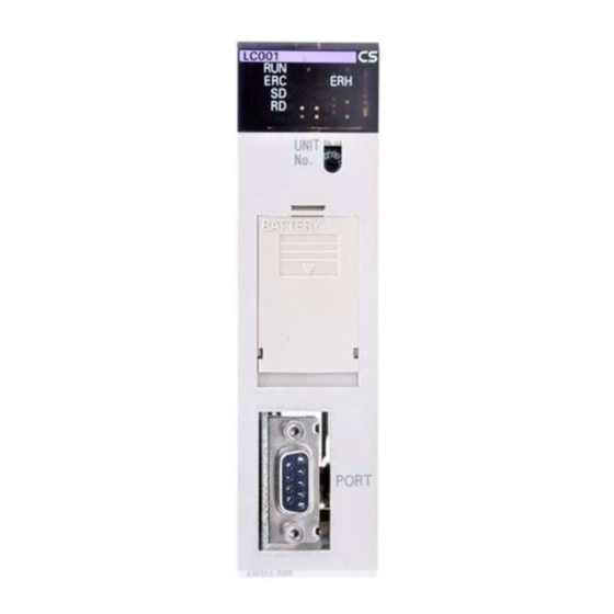
Section Names and Functions of Parts 2-1 Names and Functions of Parts 2-1-1 Names and Functions of Parts 34.5 mm LC001 LED indicators Unit number UNIT setting switch (0 to F) Battery compartment cover (for replacing 130 mm battery) Backplane connector RS-232C connector... - Page 80 Section Names and Functions of Parts LED Indicators LC001 Indication Name Color State Description Á CPU Unit Green System stopped running A probable cause is one of the following: Á Initialization of unit in progress Á Unit hardware trouble Á No power supply from power supply unit Á...
- Page 81 Section Names and Functions of Parts System Common block will be ON. (Battery errors (error code 0330) will not be stored in the error log.) When replacing the battery, replace with the following battery type. For details on how to replace the battery, see 7-2 Maintenance. Product name Model Battery set...
- Page 82 Section Names and Functions of Parts Note 2 Before turning ON pin 2 on the DIP switch, transfer the function block data to the flash memory using the CX-Process Tool. If the function block data is not stored in flash memory, RAM data will be overwritten and deleted at startup.
-
Page 83: Installation
Section Installation 2-2 Installation 2-2-1 Mountable Units The Loop Control Unit is mounted on the CPU Rack for the CS1 series. Only the three adjacent slots on the CPU Unit can be used as the mounting location. Note The Loop Control Unit cannot be mounted on the I/O Expansion Rack for the C200H and the SYSBUS Remote I/O Slave Rack. -
Page 84: Handling The Analog Input/Output Unit
Section Installation Note Be sure to tighten the mounting screw on the bottom side securely to the tightening torque of 0.4 N•m. To remove the Loop Control Unit, loosen the screw at the bottom side using the Phillips screwdriver, and lift up the bottom side to remove. Precaution When Handling the Loop Control Unit Á... -
Page 85: Connecting To Cx-Process Tool And Cx-Process Monitor
Section Connecting to CX-Process Tool and CX-Process Monitor 2-3 Connecting to CX-Process Tool and CX-Process Monitor There are two ways of connecting CX-Process Tool and CX-Process Monitor to the PC (Programmable Controller): connecting by Host Link and connecting by the Controller Link Support Board. Note CX-Process Tool and CX-Process Monitor cannot be connected directly to the Loop Control Unit. - Page 86 Section Connecting to CX-Process Tool and CX-Process Monitor The following table shows the connector cables used for connecting to the computer on which CX-Process Tool is running and to the PC (CPU Unit or Serial Communications Board/Unit). Serial Connection port communications Computer Length...
-
Page 87: Mechanism Of The Loop Control Unit
Section Configuration of Function Blocks SECTION 3 Mechanism of the Loop Control Unit 3-1 CONFIGURATION OF FUNCTION BLOCKS .......... 70 3-1-1 Configuration of Function Blocks ....................... 70 3-1-2 Preparing Function Block Data Sheets ......................70 3-1-3 ITEMs Common to All Function Blocks..................... 73 3-1-4 ITEMs Unique to Individual Function Blocks..................... -
Page 88: Configuration Of Function Blocks
Section Configuration of Function Blocks Configuration of Function Blocks All Loop Control Unit functions can be achieved by wiring the function blocks in the software. 3-1-1 Configuration of Function Blocks Function blocks comprise data items called ITEMs each starting from 000. ITEM Data Function block... - Page 89 Section Configuration of Function Blocks Allocatable block addresses are determined as follows according to the type of function block. Block addresses other than these cannot be allocated. Function block type Allocable block address Basic PID (Block Model 011) and other Control 001 to 032 blocks Square Root (Block Model 131) and other Operation...
- Page 90 Section Configuration of Function Blocks 4. Download the function block data sheets to the Loop Control Unit. Function block Function block Function block Example: Example: Example: Basic PID Basic PID Square Root (Block Mode 011) (Block Mode 011) (Block Model 131) Allocation Allocation Allocation...
-
Page 91: Items Common To All Function Blocks
Section Configuration of Function Blocks 3-1-3 ITEMs Common to All Function Blocks R/W mode Read, W: Write, R/W: R/W-enabled, Á R/W-disabled Note: r and r/w: Read and write for confirmation of CX- ITEM type ITEM No. Name Description Process Tool operation According According According... -
Page 92: Items Unique To Individual Function Blocks
Section Configuration of Function Blocks 3-1-4 ITEMs Unique to Individual Function Blocks The following table shows the ITEM types in the case of the Internal Operations block. ITEM types are divided according to connection and setup mode. Block diagram ITEM type Description Example Setting method... - Page 93 Section Configuration of Function Blocks Block diagram ITEM type Description Example Setting method symbol Accumulated This is the indication data Source designation Specify the ITEM number value input for receiving the (ITEM007) of the (accumulated value output ITEM number connection accumulation data Accumulated Value ITEM) of the block Block...
- Page 94 Section Configuration of Function Blocks Block diagram ITEM type Description Example Setting method symbol 4) Parameter value Auto/Manual switch This data is set according can be changed by (ITEM086) of the Basic to the Step Ladder the Step Ladder PID block Program block (block Program block number 301) or the...
- Page 95 Section Configuration of Function Blocks Note 1 Conventions Used in Describing ITEMs Refer to the Function Block Reference Manual. The Function Block Reference Manual defines reading and writing methods according to the following four methods as one of R: Read, W: Write, or R/W: R/W-enabled.
- Page 96 Section Configuration of Function Blocks Á ITEM type: Indicates the type of ITEM according to the following categories: (For details of categories, see 3-1-1 "Configuration of Function Blocks" in this manual. Contact input, contact output, analog input, analog output, analog input connection information, accumulated value input, accumulated value output, accumulated value input connection information and parameter Á...
- Page 97 Section Configuration of Function Blocks Note 2 All analog signals on the Loop Control Unit are processed (input or output) in % units. (They are not processed in engineering units.) Though the data range varies according to each ITEM, the maximum range is -320.00 to +320.00%.
-
Page 98: Connecting Function Blocks
Section Configuration of Function Blocks Example of multiple commands ITEM Command code (command) Operand 01 (LOAD) 001013 (block address, ITEM No.) 07 (OUT) 100011 (block address, ITEM No.) 01 (LOAD) 100011 (block address, ITEM No.) 03 (AND) 001026 (block address, ITEM No.) 07 (OUT) 002086 (block address, ITEM No.) 000 (END) - Page 99 Section Configuration of Function Blocks Connecting analog signals (variables) and accumulated value signals Specify in the analog input ITEMs which analog output ITEM and its block address are to be used to introduce analog signal function blocks on the input side. Example To introduce ITEM006 (PV) of the Basic PID block of block address 001 from ITEM011 (Y1) of the Square Root block of block address 100.
- Page 100 Section Configuration of Function Blocks Connecting via the Step Ladder Program block When logical operation is required, use the Step Ladder Program block (Block Model 301). Example Input ITEM086 (Auto/Manual switch) of the Basic PID block of block address 001, and output ITEM086 reflected in ITEM026 (Remote/Local switch) of the Basic PID block of block address 002.
- Page 101 Section Configuration of Function Blocks Connecting ITEM settable parameters Constants (fixed values) or variables (analog signals) are set by the Constant ITEM Setting block (Block Model 171) or Variable ITEM Setting (Block Model 172). To write constants (fixed values) Example Set constant 5000 (50.00) to ITEM023 (local Set Point) of the Basic PID block of block address 001.
-
Page 102: Description Of Operation
Section Description of Operation 3-2 Description of Operation 3-2-1 When Turning the Power ON to the PC Default state Function block data is not stored to the Loop Control Unit when it is shipped from the factory. CX-Process Tool must be used to prepare function blocks and download them to RAM in the Loop Control Unit. - Page 103 Section Description of Operation (2) The defaults of the System Common block on the Loop Control Unit must be set correctly. In particular, make sure that the Data Memory (D) for the Node Terminals on the CPU Unit used by the Loop Control Unit is not set in duplicate for other applications on the PC.
- Page 104 Section Description of Operation Relationship with the operation mode of the CPU Unit The Loop Control Unit continues running regardless of the operation mode of the CPU Unit. CPU Unit operation mode Running of Loop Control Unit PROGRAM mode RUN mode Running is continued.
-
Page 105: Details Of Hot Start, Cold Start And Stop State
Section Description of Operation 3-2-2 Details of Hot Start, Cold Start and Stop State There are two modes in which running of the Loop Control Unit is started: hot start and cold start. Assuming DIP switch pin 2 is OFF, the default mode for the Loop Control Unit is a hot start when the power to the PC is turned ON or the Loop Control Unit is restarted. - Page 106 Section Description of Operation Note 1 When the START mode at power ON is set to hot start, correct operation results cannot be obtained if the power is turned ON after a long power OFF. For this reason, use CX-Process Tool or CX-Process Monitor to stop running of the Loop Control Unit and start the Unit in the cold start mode to clear old data held internally in function blocks that was active before the power was turned OFF.
-
Page 107: Indicating Run/Stop Of The Loop Control Unit (Common To All Function Blocks)
Section Description of Operation 3-2-3 Indicating run/stop of the Loop Control Unit (common to all function blocks) Running of the Loop Control Unit is started according to the START mode at power ON by turning ON the power to the PC or by restarting the Loop Control Unit. - Page 108 Section Description of Operation Note 2 The following shows the relationship between the run/stop command (ITEM014) of the System Common block and the stop block operation command (ITEM000) of each function block. When the hot start mode or cold start mode has been set by run/stop command (ITEM014) of the System Common block, ITEM000 of all function blocks automatically becomes 0 (cancel stop), and operation is started by a hot start or cold start.
-
Page 109: Monitoring The Run Status Of Function Blocks
Section Description of Operation 3-2-5 Monitoring the Run Status of Function Blocks The run status of function blocks can be monitored as follows: When monitoring the run status common to all function blocks The run status common to all function blocks on the Loop Control Unit can be monitored by one of the following methods. -
Page 110: Relationship Between Cpu Unit States And Loop Control Unit States
Section Description of Operation 3-2-6 Relationship between CPU Unit states and Loop Control Unit States 3-2-6-1 Conditions for stopping and continuing running of the Loop Control Unit Running of the Loop Control Unit is stopped or continued under the following conditions. -
Page 111: Specifying The Operation Cycle
Section Description of Operation 3-2-6-4 Operation of the Loop Control Unit when the CPU Unit is in the Output OFF condition The Loop Control Unit continues to run even if the Output OFF flag causes output refreshing of the CPU Unit to stop. Note, however, that in this case contacts are not output and turn OFF, and the output hold function of the Analog Output Unit holds analog output to a specific value. - Page 112 Section Description of Operation 3-2-7-1 When executing all function blocks at a common operation cycle  Basically 1, the default operation cycle (ITEM004) of all function blocks is the system common operation cycle. (In other words, the operation cycle of each function block is interlocked with the value set at ITEM004 of the System Common block.) The default system common operation cycle (ITEM004) of the System Common block (Block Model 000) is one second.
- Page 113 Section Description of Operation Loop Control Unit Á Á System common operation cycle Specific operation cycle of only a certain function block Function block A Function block E Example: CPU Unit Example: Analog Terminal Function block F Specific operation Example: Square cycle Function block B Root...
-
Page 114: Conditions For Determining The Operation Cycle
Section Description of Operation 3-2-8 Conditions for Determining the Operation Cycle The following three conditions must be satisfied on the Loop Control Unit when determining the operation cycle: 1) The load rate (ratio between actual operation execution time and set operation time) must be 60% or less. - Page 115 Section Description of Operation Á Á Logic sequence only Logic sequence and step sequence STEP 00 STEP 00 STEP 00 STEP 00 Operation cycle LOAD 001013 LOAD 001013 AND 002012 AND 002012 OUT 100-020 OUT 100-020 Operation cycle STEP n STEP n LOAD NOT 010020 JUMP 000n...
-
Page 116: Order Of Operations
Section Description of Operation 3-2-9 Order of Operations The operation of function blocks is executed in 1) order of operation groups fixed in the system and 2) order of block addresses in each operation group in function blocks (having the same operation cycle). Operation groups fixed in the system are executed in order of the following function block categories: 1, 2, 3…... - Page 117 Section Description of Operation Operations are executed in order of block address within each group. System Common Block Model Field terminal Block Model Block Model Address order Block Model Control block Block Model Block Model Address order Block Model Terminal to All Nodes on Node Terminal Block Model Block Model...
-
Page 118: About Load Rate
Section Description of Operation The execution order is as follows: Field terminal: AI 8-point Terminal (551) Operation blocks: Square Root (131) → Non-linear Gain (133) Control block: Basic PID (011) Field terminal: AO 8-point Terminal (552) Note 2 Though "non-linear" is after "basic PID" in the software wiring, it becomes after "square root"... - Page 119 Section Description of Operation 3-2-10-1 Evaluating the load rate at the system design stage The guideline load rate for function blocks on the Loop Control Unit is 60%. At the system design stage study whether or not the load rate of each function block is 60% or less.
- Page 120 Section Description of Operation Note 3 The resolution of load rate measurement is 10 ms. (Values less than 10ms are discarded.) The readout value resolutions for each operation cycle are as follows: Operation cycle Readout resolution 0.1 sec. 0.2 sec. 0.5 sec.
- Page 121 Section Description of Operation Actual measured load rate value The actual measured load rate value is as follows according to the number of control loops and number of Step Ladder Program commands under the above conditions. The actual measured load rate values at an operation cycle of one second are as follows: Number of step ladder program Number of...
- Page 122 Section Description of Operation Total operation execution time of function block at 0.5 sec operation cycle (ms) + 10 ms = T5, Total operation execution time of function block at 1 sec operation cycle (ms) + 10 ms = T10, Total operation execution time of function block at 2 sec operation cycle (ms) + 10 ms = T20 Operation cycle...
- Page 123 Section Description of Operation Note The resolution of load rate measurement is 10 ms (the value smaller than 10 ms is discarded). The resolution of display value according to operation cycle is as follows. Operation cycle Resolution of display value 0.1 sec.
-
Page 124: External I/O Refresh Cycle On The Overall System
Section Description of Operation 3-2-10-4 Automatic operation cycle switching function When the load rate exceeds 100%, all function blocks within that group are executed even if the preset operation cycle is exceeded. In the figure below, function block F is executed even though the preset operation cycle is exceeded. - Page 125 Section Description of Operation Example Data exchange of analog input, PID operation and analog output Loop Control Unit Analog Input Unit CPU Unit Function block I/O memory Execution Analog Analog Input cycle 0.2 s Log input input block conversion Operation I/O refreshing converted cycle...
- Page 126 Section Description of Operation Á 1: Longest operation cycle in the function block group comprising the loop Á 2: Â is as follows depending on the total number of Field Terminals + CPU Unit Terminals + Expanded CPU Unit Terminals + Node Terminals + Send/Receive All Blocks ( Â...
- Page 127 Section Description of Operation à : Coefficient of the total number of function blocks exchanging data with the CPU Unit( Á 2)  : Smallest integer satisfying formula 1( Á 3) Á 1: Longest operation cycle in the function block group comprising the loop Á...
- Page 128 Section Description of Operation 3-2-11-3 Restrictions on operation cycles of function blocks used for data exchange with the CPU Unit In the case of the following function blocks that perform data exchange with the CPU Unit, the operation cycle must satisfy formula 1 shown below.
- Page 129 Section Description of Operation 1) Analog values are written on the allocated CIO area of the analog output data on the Analog Output Unit and Analog Input/Output Unit. 2) Writing is performed internally on the leading words (n) of the allocated CIO area on the Analog Output Unit and Analog Input/Output Unit.
- Page 130 Section Description of Operation Note 2 Field Terminals that do not undergo writing by the Loop Control Unit Model Function block Target Analog Internal writing by Writing of name Input/Output Unit Loop Control Unit analog values AI 8-point C200H-AD003 None None Terminal (AD003) AI 4-point...
- Page 131 Section Description of Operation When isolated-type Control Output Unit CS1W-PMV01 is used Isolated-type Control Output Units do not have a Conversion Enable flag. Disabling of conversion is indicated by the setting of the allocated Data Memory area. As the default setting, conversion is executed, and analog output values are refreshed and output.
-
Page 132: Exchanging Data With The Cpu Unit
Section Exchanging Data with the CPU Unit 3-3 Exchanging Data with the CPU Unit The Loop Control Unit exchanges the following two types of data with the CPU Unit: 1. Mutual exchange of run status 2. Exchange of any data 3-3-1 Mutual Exchange of Run Status The run status of the Loop Control Unit and the CPU Unit can be monitored... - Page 133 Section Exchanging Data with the CPU Unit To perform processing on the Loop Control Unit according to the run status of the CPU Unit To perform specific processing on the Loop Control Unit according to the run status of the CPU Unit, use the Step Ladder Program block to perform the required processing taking the following run status (ITEM007 to ITEM011, ITEM013) of the System Common block as the input conditions.
- Page 134 Section Exchanging Data with the CPU Unit 3-3-1-2 Run status of Loop Control Unit The run status of the Loop Control Unit is reflected at all times in bits 00 to 05 of the leading word n of the allocated CIO area (25 words per Unit within the range 1500 to 1899 words are occupied according to the unit number) on the CPU Bus Unit.
-
Page 135: Exchanging Any Data
Section Exchanging Data with the CPU Unit Note: If files are downloaded from the CS-Process Tool in major item units (units of Loop Control Unit), the Loop Control Unit will stop operation. If data is downloaded in function block units, however, operation will continue. This flag is thus provided so that changed in the function blocks caused by downloading from the CS-Process can be detected to implement the necessary processing. - Page 136 Section Exchanging Data with the CPU Unit Note The Loop Control Unit can use the CPU Unit Terminal block or Expanded CPU Unit Terminal block (regardless of the user program on the CPU Unit) to read and write to any I/O memory on the CPU Unit. For this reason, do not perform reading and writing in duplicate on the same I/O memory address between the Loop Control Unit and the CPU Unit.
- Page 137 Section Exchanging Data with the CPU Unit Area type CS1 Series CPU Unit Remarks I/O memory address Data Memory (D) D00000 to 32767 Including Data Memory area (words) allocated to Special I/O Unit Extended Data E0_00000 to Memory (E) bank E0_32767 No.0 Â...
- Page 138 Section Exchanging Data with the CPU Unit Note The CPU Unit Terminal or Expanded CPU Unit Terminal differs from each other in the following respect besides the number of input/output points. Data exchange timing Category DI, AI terminals DO, AO terminals CPU Unit Data is input at all times from Contact or analog data is input...
- Page 139 Section Exchanging Data with the CPU Unit 3-3-2-2 To exchange data with the CPU Unit whenever necessary (by the CMND command) The CPU issues FINS command to the Loop Control Unit from CMND command within the user program to read and write Loop Control Unit data when it requires the data.
-
Page 140: Exchanging Data With Cx-Process Monitor/Scada Software And With Other Nodes
Exchanging Data with CX-Process Monitor/SCADA Software and with Other Nodes Section 3-4 Exchanging Data with CX-Process Monitor/SCADA Software and with Other Nodes The Loop Control Unit exchanges data with CX-Process Monitor via the Data Memory for the Node Terminals that is allocated to the CPU Unit. Also, ITEMs from the Control, Operation, and External Controller Terminal Blocks can be transferred to and from I/O memory in the CPU Unit, and from there transferred to and from commercially available SCADA software. - Page 141 Exchanging Data with CX-Process Monitor/SCADA Software and with Other Nodes Section 1. System information 2. Data of Node Terminal block (Area to send to computer, Area to send to all nodes, Area to receive from all nodes) 3-4-1-1 System information System information is information such as the unit address of the Loop Control Unit and run status.
- Page 142 Exchanging Data with CX-Process Monitor/SCADA Software and with Other Nodes Section CX-Process Monitor inputs this system information data. The following table shows the details of each word of the system information. System Offset address Description of word bits information Unit address Unit number (0 to F Hex) of Loop Control Unit + 10 Hex are automatically stored to lower two bits.
- Page 143 Exchanging Data with CX-Process Monitor/SCADA Software and with Other Nodes Section 3-4-1-2 Node Terminal block data Node Terminal block data is allocated to the Data Memory for the Node Terminals following the system information. The Node Terminal block data is exclusively for data exchange with CX- Process Monitor and with Loop Controller Units at other nodes.
-
Page 144: Exchanging Data With Cx-Process Monitor
Exchanging Data with CX-Process Monitor/SCADA Software and with Other Nodes Section 3-4-2 Exchanging Data with CX-Process Monitor Mechanism for reading data from CX-Process Monitor CX-Process Monitor uses the data in the Area to send to computer on the CPU Unit to read data from the Loop Control Unit. To send data on the Loop Control Unit to this Area to send to computer, the data to be monitored must be specified by the Send to Computer blocks. - Page 145 Exchanging Data with CX-Process Monitor/SCADA Software and with Other Nodes Section 1) Specify the source designation of function block or analog/contact signal by the Send to Computer blocks (1) Specify the function block to be monitored or set by CX-Process Monitor by the 1-Block Send Terminal to Computer block (Block Model 403) or 4- Block Send Terminal to Computer block (Block Model 404) as the source designation.
- Page 146 Exchanging Data with CX-Process Monitor/SCADA Software and with Other Nodes Section Note Relationship between Screens in CX-Process Monitor and Function Blocks The following table shows the relationship between the screens in CX- Process Monitor and function blocks. Á Á Function blocks used ( : Use, : Not used) 1-Block Send...
- Page 147 Exchanging Data with CX-Process Monitor/SCADA Software and with Other Nodes Section 3-4-2-1 How to exchange data between CX-Process Monitor and the CPU Unit CX-Process Monitor supports two modes for reading data in the Area to send to computer on the CPU Unit: 1.
-
Page 148: Exchanging Data With Scada Software
Exchanging Data with CX-Process Monitor/SCADA Software and with Other Nodes Section 5) CX-Process Monitor specifies the tag number from this area to read data via the Data Link. For details on how to use the Node Terminals that use the Controller Link Data Link, see Appendix 2 How to Use the Node Terminal Block. - Page 149 Exchanging Data with CX-Process Monitor/SCADA Software and with Other Nodes Section Loop Control Unit SCADA software CPU Unit I/O memory Send All Blocks Control Block ITEMs Words specified Specify in Send All Operation tags and read Blocks Every Block ITEMs execution Receive All cycle...
- Page 150 Exchanging Data with CX-Process Monitor/SCADA Software and with Other Nodes Section The contents of a CSV tag file is shown below. Contents Setting range Record number 1 to 65535 Function block file name Max. 6 characters LCU name Max. 6 characters Tag No.
- Page 151 Exchanging Data with CX-Process Monitor/SCADA Software and with Other Nodes Section this way enables data exchange between the Loop Control Unit and PCs (CPU Unit) on the other node or Loop Control Units mounted on that PC. CPU Unit Loop Control Unit at other node Loop Control Unit CPU Unit...
- Page 152 Exchanging Data with CX-Process Monitor/SCADA Software and with Other Nodes Section For details on how to use the Node Terminals that use the Controller Link Data Link, see Appendix 2 How to Use the Node Terminal Block. Note 2 The allocation locations of each of the areas (Area to send to computer, Area to send to all nodes and Area to receive from all nodes) in Data Memory for the Node Terminals are as follows: Set at ITEM043 of...
-
Page 153: Fail-Safe Countermeasure Guidelines
Section Fail-safe Countermeasure Guidelines 3-5 Fail-safe Countermeasure Guidelines Implement fail-safe countermeasures on the Loop Control Unit according to the following guidelines. 3-5-1 Measures When the Loop Control Unit Has Stopped Running When the Loop Control Unit stops running, the state before the stop occurred is held and all operations that were being executed on the Loop Control Unit are stopped. - Page 154 Section Fail-safe Countermeasure Guidelines Contact output operation Normally, the Contact Output Unit also turns OFF when the CPU Unit changes from the RUN or MONITOR mode to the PROGRAM mode. (The I/O Memory Hold flag is used to hold output values.) However, when contact values are output via the Contact Output Unit by the Loop Control Unit, contact outputs are refreshed and then output if the CPU Unit is in the PROGRAM mode.
-
Page 155: Measures For A Cpu Unit Fatal Error
Section Fail-safe Countermeasure Guidelines 3-5-2 Measures for a CPU Unit fatal error When a fatal error occurs on the CPU Unit (including during execution of the FALS command), the Loop Control Unit also stops running. To hold the analog output to the previous value before the stop occurred, and to set the analog output to either the minimum value or maximum value, use the output hold function of the Analog Output Unit or Analog Input/Output Unit. - Page 156 Section Simple Example of Use SECTION 4 Simple Example of Use 4-1 SIMPLE EXAMPLE OF USE ..............140...
-
Page 157: Simple Example Of Use
4 to 20 mA 4 to 20 mA Control valve Product name Model Description CPU Unit CS1H/G- Loop Control Unit CS1W-LC001 Analog Input Unit CS1W-AD041 Á Analog input 1: 4 to 20 mA (temperature conversion input) Á Analog input 2:... - Page 158 Section Simple Example of Use 3. Select the required function blocks. Software type Function block name Field terminal AI 4-point (Block Model 586) AO 4-point Terminal (Block Model 587) Wiring diagram Square Root (Block Model 131) Basic PID (Block Model 011) Basic PID (Block Model 011) Basic PID AI 4-point...
-
Page 159: Section 4 Simple Example Of Use
Section Simple Example of Use 5. Decide on the data to be monitored and manipulated by CX-Process Monitor. In this example, the data of two Basic PID blocks is monitored and manipulated on CX-Process Monitor. So, specify each of the Basic PID blocks as the source designation Control block addresses in the 1-Block Send Terminal to Computer block (Block Model 403). - Page 160 Section Simple Example of Use Data range Setting ITEM Data description example 004 Operation cycle (sec.) 1 to 5 1: 0.1, 2: 0.2, 3: 0.5, 4: 1, 5: 2 018 Start mode at power ON 1 to 2 1: Hot start, 2: Cold start 042 LCU number of LC001 0 to 2 0: Basic, 1: Expansion 1, 2: Expansion 2...
- Page 161 Section Simple Example of Use 4. Wire in the software the analog signals between blocks. 5. Set the ITEMs in each function block. Set function block initial setting parameters (refer to the item "(S): Initial setting data" describing how to read/write in the Function Block Reference Manual) such as direct/reverse action and Set Point setting mode (Remote/Local) on CX-Process Tool.
- Page 162 Section Simple Example of Use When using the CX-Process Monitor 6. Set the Terminals to Computer for CX-Process Monitor. On CX-Process Tool, specify the two Basic PID blocks that are to be monitored by CX-Process Monitor as the source designation of the 1- Block Send Terminal to Computer block (Block Model 403)*1.
- Page 163 Section Simple Example of Use 8. Create (compile) the monitor tag file. When using SCADA software 6. Register a Send All Blocks, Receive All Blocks, or Expanded CPU Unit Terminal function block. 7. Set the CSV tags. 8. Create (compile) the CSV tag file Step 3 Setting up the Loop Control Unit 1, 2, 3…...
- Page 164 Section Simple Example of Use Á This Loop Control Unit cannot be set to I/O tables by editing the I/O table offline. 6. Set the communications conditions of the serial communications port in the PC system settings using the Programming Devices if necessary. 7.
- Page 165 Section Simple Example of Use Step 4 Downloading the Function Block Data to the Loop Control Unit 1, 2, 3… 1. Turn power OFF to the PC. 2. Set the DIP switches on the front panel of the CPU Unit (SW4: ON when using the peripheral port, OFF when using the RS-232C port).
- Page 166 Section Simple Example of Use Step 5 Trial Operation 1, 2, 3… 1. Execute the run/stop command on CX-Process Tool ([Execute]-[Run]- [Run/Stop Command]) or turn the PC OFF then back ON again. 2. Check system operation on CX-Process Tool. ([Execute]-[Run]-[Monitor run status]) Execute the load rate check and other diagnostic checks.
- Page 167 Section Simple Example of Use...
-
Page 168: Examples Of Function Block Combinations
Section Basic Examples of PID Control SECTION 5 Examples of Function Block Combinations 5-1 BASIC EXAMPLES OF PID CONTROL........... 152 5-1-1 Simple PID Control ........................... 152 5-1-2 Multi-channel PID Control ........................153 5-1-3 PID Control for Switching Multiple Set Points ..................154 5-1-4 PID Control for Switching PID Constants by Three Set Point Zones ............ -
Page 169: Basic Examples Of Pid Control
Section Basic Examples of PID Control 5-1 Basic Examples of PID Control This section shows basic examples of how to connect the function blocks when performing PID control. 5-1-1 Simple PID Control Function block used: Basic PID (Block Model 011) Use the Field I/O Terminal blocks (AI 4-point/AO 4-point Terminal blocks, etc.) as the analog input/outputs. -
Page 170: Multi-Channel Pid Control
Section Basic Examples of PID Control 5-1-2 Multi-channel PID Control Function blocks used: Basic PID (Block Model 011) Constant ITEM Setting (Block Model 171) Step Ladder Program (Block Model 301) Use the Field I/O Terminal blocks (AI 8-point/AO 8-point Terminal blocks, etc.) as the analog input/outputs. -
Page 171: Pid Control For Switching Multiple Set Points
Section Basic Examples of PID Control 5-1-3 PID Control for Switching Multiple Set Points Function blocks used: Basic PID (Block Model 011) Contact Selector (Block Model 165) DI Terminal from CPU Unit (Block Model 451) Register multiple Set Points for switching in advance to the Constant Selector block. -
Page 172: Pid Control For Switching Pid Constants By Three Set Point Zones
Section Basic Examples of PID Control 5-1-4 PID Control for Switching PID Constants by Three Set Point Zones Function blocks used: Basic PID (Block Model 011) ITEM Setting (Block Model 171) High/Low Alarm (Block Model 111) Step Ladder Program (Block Model 301) Register three sets of PID constants for switching in advance to the three Constant ITEM Setting blocks. - Page 173 Section Basic Examples of PID Control Block address ITEM No. Data Explanation AI 4-point Terminal block Y1 (analog input 1) AO 4-point terminal block 001087 X1 (analog output 1) source designation X1 (analog output 1) Basic PID Block 901021 PV source designation Current SP P (proportional band) I (integral time)
- Page 174 Section Basic Examples of PID Control Constant selector 1 at low limit alarm ON Constant selector 1 Low limit alarm Constant selector 2 at high limit alarm OFF and low limit alarm OFF High limit Low limit Constant selector 2 alarm alarm Constant selector 3 at high limit alarm ON...
-
Page 175: Ramp Program Control
Section Basic Examples of PID Control 5-1-5 Ramp Program Control Follow the procedure below to perform program control for changing the Set Point value in a ramp manner proportionately to the elapsed time. Function blocks used: Basic PID (Block Model 011) Ramp Program (Block Model 155) Step Ladder Program (Block Model 301) Register the ramp program (max. -
Page 176: Time-Proportional Control
Section Basic Examples of PID Control 5-1-6 Time-proportional Control Follow the procedure below to perform time-proportional control where contact output (ON/OFF) changes proportionately to the ON/OFF time ratio. Function blocks used: Basic PID (Block Model 011) Analog/Pulse Width Converter (Block Model 192) Assign the MV of the PID function block to the Analog/Pulse Width Converter block. -
Page 177: Monitoring And Accumulating Flowrate
Section Basic Examples of PID Control 5-1-7 Monitoring and Accumulating Flowrate Function blocks used: PI 4-point Terminal (Block Model 562) Accumulator for instantaneous value input (Block Model 150) Connect the instantaneous value output value of the PI 4-point Terminal block to the Accumulator for instantaneous value input block when accumulating 8-digit accumulated values based on the instantaneous values from the Pulse Input Unit CS1W-PPS01. -
Page 178: Examples Of Applied Control Types
Section Examples of Applied Control Types 5-2 Examples of Applied Control Types This section shows examples of applied control types when controlling special control targets. As the function blocks of the Loop Control Unit can be combined as desired (excluding restrictions on the number of function blocks according to function block address), use this feature to build a control system suited to your particular control requirements. -
Page 179: Cascade Control
Section Examples of Applied Control Types 5-2-1 Cascade Control In the following instances, input the MV of PID1 on the primary loop and the Remote Set Point of PID2 on the secondary loop, and connect the PC in series. This configuration is referred to as "cascade control." 1) When there are two controllable processes, and the process to be controlled is one of the processes (PV of primary loop) 2) When the other (primary loop) can be controlled by controlling the other of... - Page 180 Section Examples of Applied Control Types Note 2 In cascade control, when the secondary loop PID2 is set to Local, MV1 of the primary loop PID1 must be tracked to changes on the Local Set Point setting (LSP2) (matched to LSP2). This Loop Control Unit is provided with a bumpless MV tracking function on the primary and secondary sides during cascade processing in ITEM032 (bumpless processing between primary/secondary loops) in the Basic PID...
- Page 181 Section Examples of Applied Control Types Block address ITEM No. Data Explanation AI 4-point Terminal block Y1 (analog input 1) Y2 (Analog input 2) AO 4-point terminal block 002087 X1 (analog output 1) source designation X1 (analog output 1) Advanced PID block 901021 PV source designation Advanced PID block 901022 PV source designation...
-
Page 182: Feedforward Control
Section Examples of Applied Control Types 002-086 001-085 • The MV tracking switch turns OFF when PID2 is set to Auto, and turns ON when PID2 is set to Manual. Secondary Auto/Manual MV tracking switch 5-2-2 Feedforward Control Before the influence of disturbances such as load fluctuation appears in the process result, disturbance is detected beforehand to correct MV so that its influence is canceled. - Page 183 Section Examples of Applied Control Types K2: Disturbance gain The step response in this model is as follows: T1 > T2 T1=T2 Á Feedforward K1 Â T2 control T1 < T2 As shown above, when T1 (time constant of process) is longer than T2 (time constant of disturbance) (T1>T2), a lead is applied to the feedforward control signals (lead compensation).
- Page 184 Section Examples of Applied Control Types Block address ITEM Data Explanation AI 4-point Terminal block Y1 (analog input 1) Y2 (analog input 2) AO 4-point terminal block 001087 X1 (analog output 1) source designation X1 (analog output 1) Advanced PID block 901021 PV source designation 100013 MV compensation (addition) Lead/delay operation blocks...
-
Page 185: Sample Pi Control
Section Examples of Applied Control Types Note 5 Noninteracting control elements generally are one cause of lag. Set Point Control output Process PID control characteristics − − Noninteracting contorl element Set Point Noninteracting contorl element − Control output Process PID control characteristics −... - Page 186 Section Examples of Applied Control Types Advanced PID Block Model 012 MV hold Contact Distributor Block Model 201 ON/OFF operation ON/OFF Timer Start of operation Block Model 206 The contact signals from the ON/OFF Timer block are connected to the MV hold input of the Advanced PID block.
-
Page 187: Dead Time Compensation
Section Examples of Applied Control Types Block address ITEM No. Data Explanation AI 4-point Terminal block Y1 (analog input 1) AO 4-point Terminal block 001087 X1 (analog output 1) source designation X1 (analog output 1) Advanced PID block 901021 PV source designation MV hold switch ON/OFF Timer block Contact output... - Page 188 Section Examples of Applied Control Types Note 2 By dead time compensation control, dead time compensation is performed on MV as shown below and the result is added to the PV of PID control. Dis turbance Control output Process PID control Set Point characteristics −...
- Page 189 Section Examples of Applied Control Types Example Rotary drier Moisture meter Advanced PID <Block Model 012> Address 001 Analog Analog input output PV compensation sw itch PV compensation mode: "Add" PV compensation input Dead Time Compensation <Block Model 149> Address 101 Block address ITEM Data...
-
Page 190: How To Use Fins Commands
Section How to Use FINS Commands SECTION 6 How to Use FINS Commands 6-1 HOW TO USE FINS COMMANDS ............174 6-2 FINS COMMAND LIST ................177 6-3 DESCRIPTION OF FINS COMMANDS............ 178... - Page 191 Section How to Use FINS Commands How to Use FINS Commands FINS commands can be issued to the Loop Control Unit by one of the following two methods: 1) By the CMND (DELIVER COMMAND) instruction from the CPU Unit 2) By the Host Link or the networked host computer 1) By the CMND (DELIVER COMMAND) instruction from the CPU Unit FINS commands can be issued to the Loop Control Unit by executing the CMND (DELIVER COMMAND) instruction in the program on the CPU Unit or...
- Page 192 Section How to Use FINS Commands 4. When the FINS response frame is returned from the Loop Control Unit, data conforming to the response format is stored to the response address. 5. The response is then read when the Network Communications Enabled Flag corresponding to the communications port number to be used turns For details, refer to items describing the CMND (DELIVER COMMAND) instruction in the Communications Commands Reference Manual (Cat.
-
Page 193: Section 6 How To Use Fins Commands
Section How to Use FINS Commands 2) By the Host Link or the networked host computer The FINS command frame is sent to the Loop Control Unit delimited by the Host Link header or terminator from the host computer. CPU Unit Loop Control Unit FINS command Response... -
Page 194: Fins Command List
Section FINS Command List 6-2 FINS Command List Command Name Description (Hex) 0240 READ MULTIPLE Reads specified continuous Note: Specifiable ITEMs are all ITEMS FROM (multiple) ITEMs from a single ITEMs in all blocks FUNCTION BLOCK function block. excluding the sequence commands (ITEM011 0241 WRITE MULTIPLE... -
Page 195: Description Of Fins Commands
Section Description of FINS Commands 6-3 Description of FINS Commands This section describes the command and response formats for FINS commands issued to the Loop Control Unit. command code READ MULTIPLE ITEMS FROM FUNCTION BLOCK 02 40 Function Reads multiple ITEMs from a single function block. Command format Parameter Command code... - Page 196 Section Description of FINS Commands Note 2 When one or more ITEMs has been read correctly, this shall be regarded as a normal completion. By a normal completion, the number of ITEMs that were read correctly and the data of the number of ITEMs that were read correctly (1 to number of ITEMs) are returned as the FINS response.
- Page 197 Section Description of FINS Commands command code WRITE MULTIPLE ITEMS TO FUNCTION BLOCK 02 41 Function Writes multiple ITEMs in a single function block. Command format Parameter Data Command code Data Number Write start Write data Á repeated type (block length format of ITEMs...
- Page 198 Section Description of FINS Commands Note 2 Specify the write start address, data length and write data for the number of ITEMs. Response format Command code Response code Data format 02 Hex 41 Hex MRES SRES Data length (bytes) When all ITEMs to be written can be written, and all ITEMs have been written successfully, this shall be regarded as a normal completion.
- Page 199 Section Description of FINS Commands command code READ ITEM FROM MULTIPLE FUNCTION BLOCKS 02 42 Function Reads the specified ITEM from multiple function blocks. Command format Parameter Command code Number Read start Á repeated Data format type (block of ITEMs address 02 Hex 42 Hex...
- Page 200 Section Description of FINS Commands Note 3 For details of the data length of each ITEM, refer to the rightmost column "Data length (bytes)" in the ITEM Lists in Section 2 Description of Function Blocks in the Function Block Reference Manual. Response code Response code Meaning...
- Page 201 Section Description of FINS Commands command code WRITE ITEM TO MULTIPLE FUNCTION BLOCKS 02 43 Function Writes the specified ITEM to multiple function blocks. Command format Parameter Data Command code Data Number Write start Write Á repeated type (block length format of ITEMs address...
- Page 202 Section Description of FINS Commands Note 2 Specify the parameter type, write start address, data length and write data for the number of ITEMs. Response format Command code Response code Data format 02 Hex 43 Hex MRES SRES Data length (bytes) When all ITEMs to be written can be written, and all ITEMs have been written successfully, this shall be regarded as a normal completion.
- Page 203 The model number is filled with spaces (20 Hex) from the right if less than 20 characters. The model number of the Loop Control Unit is "CS1W-LC001." 2) Version The version of the system program comprising up to 20 ASCII code characters beginning from the left is returned.
- Page 204 Section Description of FINS Commands command code ECHOBACK TEST 08 01 Function Performs an echoback test with the Loop Control Unit. This test is used to check whether or not FINS protocol communications with the Loop Control Unit is functioning normally. Command format Command code Data format...
- Page 205 Section Description of FINS Commands command code READ ERROR LOG 21 02 Function Reads the error log on the Loop Control Unit. The configuration of each error log is as follows, and error logs are stored in RAM (battery-backed up) on the Loop Control Unit. The configuration of each error log is as follows and is regarded as a single record.
- Page 206 Section Description of FINS Commands 3) Number of read records The actual number of read records is returned in Hex. 4) Error code Indicates the error details as a code. For details on error codes, see 7-1 Errors and Alarm Troubleshooting. 5) Detailed information Indicates the detailed information of the error.
- Page 207 Section Description of FINS Commands command code CLEAR ERROR LOG 21 03 Function Clears the error log on the Loop Control Unit. Command format Command code Data format 21 Hex 03 Hex Data length (bytes) Response format Command code Response code Data format 21 Hex 03 Hex...
-
Page 208: Errors And Alarm Troubleshooting
Section Errors and Alarm Troubleshooting SECTION 7 Errors and Alarm Troubleshooting 7-1 ERRORS AND ALARM TROUBLESHOOTING........192 7-1-1 Judging Errors by Indicators........................192 7-1-2 Error Log Data............................195 7-1-3 System Information ........................... 195 7-1-4 Execution Error Code List ......................... 196 7-2 MAINTENANCE ................... -
Page 209: Errors And Alarm Troubleshooting
Section Errors and Alarm Troubleshooting 7-1 Errors and Alarm Troubleshooting 7-1-1 Judging Errors by Indicators LC001 Indication Name Color State Description Á CPU Unit Green System stopped running A probable cause is one of the following: Á Initialization of unit in progress Á... - Page 210 Section Errors and Alarm Troubleshooting Errors that occur during initial processing (at CPU Unit power ON or restart of the Loop Control Unit) Error code Item Cause State (stored as Remedy error log data) Out Unit 1) The same unit All functions None 1) Set the correct unit...
-
Page 211: Section 7 Serrors And Alarm Troubleshooting
Section Errors and Alarm Troubleshooting Error that occur during regular running Error code Item Cause State (stored as Remedy error log data) Normal CPU Unit running None Running stopped Normal or None load rate One of the following: Á exceeded Regular running stop operation... -
Page 212: Error Log Data
Section Errors and Alarm Troubleshooting 7-1-2 Error Log Data The configuration of error log data including error codes is as follows. Error log data is stored in RAM (battery-backed up) on the Loop Control Unit. The configuration of each error log is as follows and is regarded as a single record. -
Page 213: Execution Error Code List
Section Errors and Alarm Troubleshooting 7-1-4 Execution Error Code List Á The execution error codes shown in the list below are stored in ITEM003 of each function block. Á When there are function blocks containing an error other than 0 (normal), the smallest block number in these function block numbers is stored to ITEM093 of the System Common block (Block Model 000). - Page 214 Section Errors and Alarm Troubleshooting Code Description Explanation Operation at error Remedy calculated. Inappropriate Two or more S1 to S3 select The output value that was Re-program the Step Ladder operation switches are set to 1 (ON) at the active before the error Program block so that S1 to same time in the 3-output Selector occurred is held.
- Page 215 Section Errors and Alarm Troubleshooting Code Description Explanation Operation at error Remedy Controller unit The unit number set in ITEM 006 for Communications will be Change unit number number a ES100X Controller Terminal stopped with the ES100X settings (ITEM 006)so that duplicated (Block Model 045) is the same as Controllers.
-
Page 216: Maintenance
Section Maintenance 7-2 Maintenance 7-2-1 Replacing the Loop Control Unit Follow the procedure below to replace the Loop Control Unit. When the same function block file (appended by the .ist extender) as the function block data on the Loop Control Unit is held in storage To use the parameters (on the Loop Control Unit that is to be replaced) that were set on CX-Process Monitor 1, 2, 3…... -
Page 217: Using The Flash Memory
Section Maintenance 6. If necessary, use CX-Process Tool to compare all function block files to check whether or not the download has been executed successfully. 7. Check the Loop Control Unit again for any malfunction. 8. Use CX-Process Monitor to set the parameters. When the same function block file (appended with the .ist extender) as the function block data on the Loop Control Unit is not set aside Note... - Page 218 Section Maintenance Á To back up and recover memory if a battery error occurs during normal operation Note 1 Before turning ON pin 2 on the DIP switch, transfer the function block data to the flash memory using the CX-Process Tool. If the function block data is not stored in flash memory, RAM data will be overwritten and deleted at startup.
-
Page 219: How To Replace The Battery
Section Maintenance 5. Turn OFF the power supply to the PC. 6. Turn ON pin 2 of the DIP switch. 7. Turn ON the power supply to the PC. The contents of flash memory will be copied to RAM and operation will start. 8. - Page 220 Section Maintenance LC001 UNIT BA TTE RY 3. Remove the battery together with its connector. LC001 LC001 UNIT UNIT 4. Replace the old battery with a new battery within five minutes. When removing the battery from the battery holder, take care not to catch the connector cable on the battery holder.
- Page 221 Section Maintenance Replacement cycle: The ERC LED on the front panel of the Loop Control Unit starts to blink when the internal battery voltage drops or the battery is not connected. Replace the Loop Control Unit within five days of the ERC LED (red) starting to blink. When the ERC LED starts to blink (red), ITEM095 of the System Common block (Block Model 000) turns ON, and error log code 0330 is stored on the Loop Control Unit.
-
Page 222: How To Use The Step Ladder Program Block
Appendix 1 How to Use the Step Ladder Program Block Appendix 1 How to Use the Step Ladder Program Block The Step Ladder Program block (Block Model 301) is used in the following cases: Á When logical operations such as AND, OR and NOT are to be performed on the Loop Control Unit Á... - Page 223 Appendix 1 How to Use the Step Ladder Program Block Á Note 1 The execution cycle of sequence commands in the Step Ladder Program block is slower than the execution cycle (cycle time) of commands on the CPU Unit. (0.1 to 2 s cycles follow the operation cycle of the Step Ladder Program itself.) For this reason, the Step Ladder Program block is used combined with other function blocks.
- Page 224 Appendix 1 How to Use the Step Ladder Program Block List of Basic Instructions : Can be used Á Cannot be used Command Input Command Ladder symbol Operand Description code conditions In logic In step sequence sequence LOAD Read Indicates a logical start Not required source of the logic block,...
- Page 225 Appendix 1 How to Use the Step Ladder Program Block : Can be used Á Cannot be used Command Input Command Ladder symbol Operand Description code conditions In logic In step sequence sequence Write Outputs the result Required destina- (execution condition) of tion block logical processing: 0 address/...
- Page 226 Appendix 1 How to Use the Step Ladder Program Block : Can be used Á : Cannot be used Command Input Command Ladder symbol Operand Description code conditions In logic In step sequence sequence   Draw line Connects vertical or horizontal lines.
- Page 227 Appendix 1 How to Use the Step Ladder Program Block List of Sequence Control Instructions : Can be used Á : Cannot be used Command Input Command Ladder symbol Operand Description code conditions In logic In step sequence sequence STEP Step STEP declares the step Not required...
- Page 228 Appendix 1 How to Use the Step Ladder Program Block : Can be used Á : Cannot be used Command Input Command Ladder symbol Operand Description code conditions In logic In step sequence sequence Á Á JUMP Block When the input conditions Required turn ON, execution of the address/...
- Page 229 Appendix 1 How to Use the Step Ladder Program Block  To receive data internally by the Step Ladder Program without outputting it to the block address and ITEM number, specify the Internal Switch block (Block Model 209) as the block address. Example ITEM Command...
- Page 230 Appendix 1 How to Use the Step Ladder Program Block When a single step is used as a logic sequence The default step is STEP000. STEP000 operates at all times when the operating conditions are satisfied. This step operates when run/stop command S1 (ITEM008) of the Step Ladder Program block turns ON. Single step (normal) ITEM Command...
- Page 231 Appendix 1 How to Use the Step Ladder Program Block  To break up a Step Ladder Program, use the STEP command (21). (The default step for the Step Ladder Program block is the constant operation step STEP00.)  When run/stop command S1 (ITEM008) of the Step Ladder Program block turns ON, STEP00 (constantly available step) and STEP01 (first step of step sequence) operate.
- Page 232 Appendix 1 How to Use the Step Ladder Program Block How to program for step progression control To execute specific processing in each process, program the step sequence as follows: 1) Execute the SET command at the end of STEP n as the input condition for moving to another step, and set the internal switch.
- Page 233 Appendix 1 How to Use the Step Ladder Program Block Example of Step Ladder Program S T E P 0 1 D e c la r e S T E P 0 1 . S t a r t o f o p e r a t i o n I T E M s e t t i n g 0 0 0 - 0 1 9...
-
Page 234: How To Use The Node Terminal Blocks
Appendix 2 How to Use the Node Terminal Block Appendix 2 How to Use the Node Terminal Block Application of the Node Terminal Block The Node Terminal Block is used in the following cases: 1, 2, 3… 1. To use CX-Process Monitor or to read data for monitoring the Loop Control Unit from the host computer 2. - Page 235 Appendix 2 How to Use the Node Terminal Block There are two modes of exchanging data between the host computer and Loop Control Unit. Method On-demand reading mode Data link mode Description Host computer on which CX-Process Host computer on which CX-Process Monitor is running reads the Area to send to Monitor is running uses the Data Link computer whenever required.
- Page 236 Appendix 2 How to Use the Node Terminal Block Note The Loop Control Unit can also re-issue the data written from the computer to the Controller Link network. When data is re-issued, the Loop Control Unit internally writes the data to the Area to send to all nodes in Data Memory (on CPU Unit) for the Node Terminals, and sends the data to the Loop Control Unit at another node PC by the Controller Link Data Link.
- Page 237 Appendix 2 How to Use the Node Terminal Block Á During data reception: DI Terminal from All Nodes (Block Model 414) AI Terminal from All Nodes (Block Model 415) The self node PC receives the data that was sent from the Loop Control Unit at the other node PC by the Controller Link Data Link.
- Page 238 Appendix 2 How to Use the Node Terminal Block Basic Procedure Step 1. Initial setting to System Common blocks Step 2. Wiring in software of Terminal to All Nodes Send block or Terminal from All Nodes Receive block Step 3. Connection/setting of Controller Link Step 4.
- Page 239 Appendix 2 How to Use the Node Terminal Block Configuration of Data Memory for the Node Terminals Set at ITEM043 of System Common blocks Data Memory (D) for Node Terminals Á For LCU number 8 words Leading address S Unit address System For LCU number 8 words...
- Page 240 Appendix 2 How to Use the Node Terminal Block Relationship between Data Memory (on CPU Unit) for Node Terminals and Node Terminal Block Data Memory (on CPU Unit) for the Node Terminals corresponds to the Node Terminal blocks shown in the table below.
- Page 241 Appendix 2 How to Use the Node Terminal Block How to Set Controller Link Data Link Tables When the Node Terminal block is used to send and receive data to and from the personal computer on the Controller Link or a Loop Control Unit at another PC, the Controller Link Data Link (user setting) table (Note) shown below must be prepared and registered (downloaded) on each node.
- Page 242 Appendix 2 How to Use the Node Terminal Block Example of connection mode 1) Using Controller Link to connect to CX-Process Monitor System information (24 words) and Area to send to computer (512 words) are sent over the Data Link. Loop Control Unit CX-Process Monitor...
- Page 243 Appendix 2 How to Use the Node Terminal Block Actual example The following shows a simple example. PID1 Basic PID Block AI 4-point Model 011 Terminal Block Model 586 PID2 Basic PID Block Model 011 AO 4-point Terminal Block Model 587 In the above example, basic PID is specified as follows on the 1-Block Send Terminal to Computer (Block Model 403) as the source designation function block address.
- Page 244 Appendix 2 How to Use the Node Terminal Block Block addresses 501 and 502 are each sent (allocated) to the Area to send to computer of the Data Memory area for the node terminals. When the leading address (S) of the Data Memory area for the Node Terminals is taken to be D16020 (set to ITEM043): Data Memory (D) for Node Terminals D16020...
- Page 245 Appendix 2 How to Use the Node Terminal Block Connection mode 2) Connecting with the Loop Control Unit at another node PC and the computer on which CX-Process Monitor is running Data link table settings Item Description Data link type Any setting Link start word Leading address (S) of Data Memory for the node...
- Page 246 Appendix 2 How to Use the Node Terminal Block Note 2 In addition to connection mode 2) above, the CPU Unit Terminal block or Expanded CPU Unit Terminal block can be used to read and write the Data Link area after building a regular Controller Link Data Link as a method of connecting the Loop Control Unit to another node PC.
- Page 247 Appendix 2 How to Use the Node Terminal Block Data Link table of PC#1 Á A total of 636 words (S to S+635 words) comprising system information (24 words), Area to send to computer (512 words) and Area to send to all nodes (100 words) are sent to the computer. Á...
-
Page 248: List Of Operation Execution Times
Appendix 3 List of Operation Execution Times This appendix describes the operation execution times for each of the function blocks. How to Calculate the Load Rate Calculate the load rate based on the following formula. This equation merely serves as a guideline, and the load rate may differ from the actually measured load rate. - Page 249 Appendix 3 List of Operation Execution Times When mixed operation cycles are used After calculating the load rates of each operation cycle by the above equation, add the load rates of each operation cycle to correct the operation cycles. Ã When the load rate of the shortest operation cycle is taken to be %, add the following values to the load rates of each operation cycle.
- Page 250 Appendix 3 List of Operation Execution Times List of Operation Execution Times for Function Blocks Block Operation Block name Remarks model execution time System Common 1.05 The load rate increases by 0.40% at an operation cycle of 100 ms. 2-position ON/FF 0.74 3-position ON/OFF 0.77...
- Page 251 Appendix 3 List of Operation Execution Times Block Operation Block name Remarks model execution time Temperature and Pressure 0.74 Correction First-order Lag 0.46 Rate-of-change Limit 0.45 Moving Average 0.55 Lead/Delay 0.50 Dead Time 0.57 Dead Time Compensation 0.56 Accumulator for instantaneous 0.59 value input CPU Unit Running Time...
- Page 252 Appendix 3 List of Operation Execution Times Block Operation Block name Remarks model execution time Motor Opening Manipulator 0.53 The load rate increases by 0.29% at an operation cycle of 100 ms. Ã Step Ladder Program 3.39 The sequence command execution times shown in the following table must be added.
- Page 253 Appendix 3 List of Operation Execution Times Block Operation Block name Remarks model execution time AI 8-point Terminal (PTR01/02) 0.44 AI 4-point/AO 4-point Terminal 0.71 (MAD44) AI 8-point Terminal (AD081) 0.51 AO 8-point Terminal 1.48 (DA08V/C) AI 4-point Terminal (AD041) 0.40 AO 4-point Terminal (DA041) 0.83...
- Page 254 Appendix 3 List of Operation Execution Times Unit: ms Block Block name Time for Time for model Receive All Send All Blocks (Block Blocks (Block Model 461) Model 462) Accumulated Value 0.31 0.10 Analog Multiplier Accumulator for 0.28 0.11 accumulated value input Contact 0.07...
- Page 255 Appendix 3 List of Operation Execution Times Sequence Command Execution Times When the Step Ladder Program (Block Model 301) is used, add the following command execution times to the operation execution time (3.39 ms) of the sequential control program itself. Command code Command Execution time (ms)
-
Page 256: Index
Index function block, 20, 70 AI Terminal from CPU Unit, 31 AI Terminal from Expanded CPU Unit, 31 AI x-point Terminal, 30 hot start, 87 AI x-point/AO x-point Terminal, 30 ITEM, 70, 74 AO Terminal to CPU Unit, 31 AO Terminal from Expanded CPU Unit, 31 AO x-point Terminal, 30 load rate, 28, 100 logic sequence, 213... -
Page 257: Revision History
Revision History A manual revision code appears as a suffix to the catalog number on the front cover of the manual. W374-E1-3 Cat. No. Revision code The following table outlines the changes made to the manual during each revision. Page numbers refer to the previous version.
Need help?
Do you have a question about the CS1W-LC001 and is the answer not in the manual?
Questions and answers