
Related Manuals for Festo CHB-C-N


Summary of Contents for Festo CHB-C-N
- Page 1 Checkbox Compact Description Function Type CHB-C-N Description 8046182 en 1508e [8043163]...
- Page 2 Festo Checkbox ® is a registered trademark of Festo AG & Co. KG, 73726 Esslingen, Germany...
- Page 3 ....... . . 8046182 E (Festo AG & Co. KG, 73726 Esslingen, Germany, 2015) Internet: http://www.festo.com e-mail: service_international@festo.com...
- Page 4 ............3-16 Festo GDCA-CHB-C-N en 1508e English...
- Page 5 ........Festo GDCA-CHB-C-N en 1508e English...
- Page 6 ............Festo GDCA-CHB-C-N en 1508e English...
-
Page 7: Intended Use
Please observe the standards specified in the relevant chapters and comply with the regulations of the trade associ ation and the German Technical Control Board (TÜV), the VDE conditions as well as the relevant national regulations. Festo GDCA-CHB-C-N en 1508e English... - Page 8 Checkbox Compact uses parallel light, the risk of eye injury is not reduced as the distance increases; this applies to both looking directly at the beam and looking into the beam via a reflective surface. Festo GDCA-CHB-C-N en 1508e English...
-
Page 9: Scope Of Delivery
This description is intended exclusively for technicians trained in control and automation technology who have ex perience in installing and commissioning electronic systems. Service Please consult your local Festo Service if you have any tech nical problems. Scope of delivery Checkbox Compact... - Page 10 Electrostatically sensitive devices. Incorrect handling can result in damage to components. Marking of special information The following pictograms mark passages in the text which contain special information. VIII Festo GDCA-CHB-C-N en 1508e English...
- Page 11 You will therefore find e. g. in the path System Operating modes the parameter Lock the Teach button = Off – Inputs and outputs of the plug connectors are specified with the pin number as follows: Input pin 1 Output pin 2 Festo GDCA-CHB-C-N en 1508e English...
- Page 12 Contents and general safety instructions – Plug connectors are represented as when viewed on the device. This representation corresponds to the view of the (cable) connections which are to be wired. Festo GDCA-CHB-C-N en 1508e English...
- Page 13 Contents and general safety instructions Information regarding this description This description refers to the standard designs of the Check box Compact type CHB-C-N with operating system version 3.5. The version number is shown on the display in the stop status (see chapter 2.5).
- Page 14 Orientation 1 is the preferred orientation (nominal orientation). RUN mode Operating mode of the Checkbox for automatic parts testing (preset when starting the CHB-C-N). AUTO mode in earlier versions. Sample parts Good parts which have been selected for the Teach procedure and which possess all the features necessary for identifying the check program.
- Page 15 Program with tools defined by the teach data of the sample parts (configuration in CheckOpti). Tolerance Factor in per cent related to the average values and which affects the min./max. limits of all features. Tab. 0/2: Terms and abbreviations XIII Festo GDCA-CHB-C-N en 1508e English...
- Page 16 Contents and general safety instructions Festo GDCA-CHB-C-N en 1508e English...
-
Page 17: System Overview
System overview System overview Chapter 1 Festo GDCA-CHB-C-N en 1508e English... -
Page 18: Table Of Contents
........... . Festo GDCA-CHB-C-N en 1508e English... -
Page 19: System Overview
(contactless) posi tioning and quality inspection of conveyed parts and it pre cisely controls the actuators for sorting the inspected parts and parts assigned to the result groups (tracking, ejection of parts, etc.). Festo GDCA-CHB-C-N en 1508e English... -
Page 20: Software Package
Tool (FFT) – Changing network settings (IP address) Tab. 1/1: Software package The software package, operating system updates and current product information on the Checkbox Compact can be found on the Festo website at www.festo.com/sp. Festo GDCA-CHB-C-N en 1508e English... -
Page 21: Function Range
– Supplying of defined amounts of components through specification of a target number for good parts. Extended quality inspection with CheckOpti The system parameters must be activated or set in CheckKon Tab. 1/2: Function range Festo GDCA-CHB-C-N en 1508e English... -
Page 22: Operational Principle
Further transfer of good parts to a buffer zone or the next machine Actuators e.g. exhaust valves Transporting device e.g. conveyor belt, linear axis Fig. 1/1: Integration of the Checkbox in a transporting device: Example with conveyor belt and two actuators Festo GDCA-CHB-C-N en 1508e English... - Page 23 2. You scan the sample parts in further orientations if required. 3. You save the features of the check program as Teach data. 4. You test the Teach data in the test mode. Festo GDCA-CHB-C-N en 1508e English...
- Page 24 3 conveying paths: – Good parts are passed on e.g. to an assembly system. – Incorrectly oriented parts are returned to the small parts conveyor. – Faulty or foreign parts (defective parts) are rejected. Festo GDCA-CHB-C-N en 1508e English...
-
Page 25: Buffer Zone
Dimensioning the buffer zone The buffer zone sections (see Fig. 1/2) must be dimensioned so that uninterrupted operation of the machine is possible. Instructions on dimensioning the buffer zone can be found in the following table. Festo GDCA-CHB-C-N en 1508e English... - Page 26 The longer the section is, the less the switching frequency. *) Set the “Number of buffer zone sensors = 2” with CheckKon Tab. 1/3: Buffer zone sections Also observe Chapter 3.3 and Chapter 3.6.5 when connecting the buffer zone sensors. 1-10 Festo GDCA-CHB-C-N en 1508e English...
- Page 27 1. System overview Transporting device Sensor 1 Fig. 1/2: Buffer zone check Transporting device Sensor 2 Sensor 1 Fig. 1/3: Buffer zone check with hysteresis 1-11 Festo GDCA-CHB-C-N en 1508e English...
- Page 28 1. System overview 1-12 Festo GDCA-CHB-C-N en 1508e English...
-
Page 29: Mounting And Commissioning
Mounting and commissioning Mounting and commissioning Chapter 2 Festo GDCA-CHB-C-N en 1508e English... - Page 30 ..........2-27 Festo GDCA-CHB-C-N en 1508e English...
-
Page 31: Mounting And Commissioning
When mounting and removing, make sure nothing can fall • Only carry out commissioning procedures when fully • mounted Caution Damage to components. Before carrying out mounting, installation and/or main • tenance work, always switch off the power supply. Festo GDCA-CHB-C-N en 1508e English... - Page 32 (for example, by providing screening). Do not stare directly into the light beam and do not dir • ect the beam into the eyes of other people. Prism support Opening for the light beam Fig. 2/1: Lighting Festo GDCA-CHB-C-N en 1508e English...
-
Page 33: Mounting
Ensure the stable position of the parts, e.g. by means of • mechanical devices. Ensure a good transfer of parts from the small parts con • veyor to the transporting device and that the transporting device is mechanically decoupled from the small parts conveyor. Festo GDCA-CHB-C-N en 1508e English... - Page 34 Only modify the Checkbox in a clean environment • Only use suitable screws. The screw-in depth in the • device is limited to a maximum of 6 mm. A connecting kit (type HMSV-12) is available as an accessory from Festo. Festo GDCA-CHB-C-N en 1508e English...
- Page 35 To achieve maximum contrast for small details, mount the device in such a way that the objects are passed as close as possible to the prism support on the sensor side. This is the side with the Start/Stop button. Festo GDCA-CHB-C-N en 1508e English...
- Page 36 Mount the Checkbox so that passing parts do not touch • the glass surfaces. Ensure the stable position of the parts, e.g. by means of • mechanical devices. If necessary, clean the glass surfaces, as described in • chapter 6 Festo GDCA-CHB-C-N en 1508e English...
-
Page 37: Electrical Connection
– Connection of 2 buffer zone sensors for controlling the flow of parts to the next machine – 24 V power output for controlling the supply system (small parts conveyor) and the transporting device – I/O signals for process monitoring and higher-order control or for controlling a downstream-switched machine Festo GDCA-CHB-C-N en 1508e English... - Page 38 EMERGENCY STOP (e.g. switching off the operating voltage, switching off pressure). Preparing plugs and cables Use plugs and sockets from the Festo supply programme which match the outer diameter of the cables used (www.festo.com/catalogue). Note Angled connectors can transfer large forces into the de...
- Page 39 Connect both the FE earth terminal and the cable screen • ing with low impedance to the earth potential. At the FE connection on the front panel, use an earthing • strap with a suitable cross section. 2-11 Festo GDCA-CHB-C-N en 1508e English...
- Page 40 To ensure optimum attenuation of the voltage over • shoot, the supply cable should not be of too low an im pedance. Festo therefore recommends a cross section of 1.0 or 1.5 mm² Observe the maximum load capacity of the cable.
- Page 41 Do not overload the cables. Cable outside diameter Plugs/sockets 4.0 ... 6.0 mm PG 7 6.0 ... 8.0 mm PG 9 10.0 ... 12.0 mm PG 13.5 Tab. 2/1: Cable outside diameter 2-13 Festo GDCA-CHB-C-N en 1508e English...
- Page 42 Tighten the union nuts of the plug connectors by hand. • Seal unused sockets with the protective caps supplied. • Caution Long I/O signal lines reduce the resistance to interference. Comply with the maximum permissible I/O signal line • length of 30 m. 2-14 Festo GDCA-CHB-C-N en 1508e English...
-
Page 43: Selecting The Power Supply Unit
Make sure the power supply unit fulfils the requirements spe cified in the Checkbox data sheet with regard to voltage, cur rent and power. Allow for a sufficient power reserve. Observe the power consumption of connected consumers as well as system expansions. 2-15 Festo GDCA-CHB-C-N en 1508e English... -
Page 44: Connection Of The Operating Voltage
Use only a 4-pin M18 socket for the power supply and con nect this only to the connection for the power supply. 1. Connect the plug to the 24 V DC connection on the Checkbox. 2. Tighten the union nuts of the plug by hand. 2-16 Festo GDCA-CHB-C-N en 1508e English... -
Page 45: Power Supply For External Components
“24 V DC” connection of the Checkbox with other plug con nectors of the Checkbox. Current-consuming devices can also be supplied with voltage via the PLC plug. Observe also the information in chapter 3.6. 2-17 Festo GDCA-CHB-C-N en 1508e English... -
Page 46: Adapting System Parameters With Checkkon
Adapting system parameters with CheckKon A password is required for CheckKon for setting the system parameters and transmitting the modifications to the Check box (function “Modify system”). Consult your Festo Service. Install CheckKon on your diagnostic PC. Installation in •... - Page 47 2. Mounting and commissioning Note Faulty processing data can cause incorrect functioning of the Checkbox. Carry out the complete Teach procedure again if you • have modified the system parameters with CheckKon (see chapter 4). 2-19 Festo GDCA-CHB-C-N en 1508e English...
-
Page 48: Commissioning The Checkbox
– Save the Teach data – Switch between RUN and Teach modes – Select the orientation in the Teach mode – Display the scan procedure – Call up system information (e.g. belt speed during operation with encoder) 2-20 Festo GDCA-CHB-C-N en 1508e English... - Page 49 In order to prevent the transporting device from starting automatically when the operating voltage is switched on, observe the following: Select in CheckKon [View] [System parameter] System • Operating modes Automatic start after power sup ply on = no (factory setting). 2-21 Festo GDCA-CHB-C-N en 1508e English...
- Page 50 Readiness to operate is signaled by the STOP status – The IP address (factory setting: 192.168.2.20) indicates the current IP address of the device – CHB-C-N firmware version number (3.5.3) (Hash value of the firmware version 1b95f81806a6) 2-22 Festo GDCA-CHB-C-N en 1508e English...
- Page 51 Sctr: Scatter of characteristics (110) indicates the max – imum value for the scatter of characteristics Prog: Check program number (1) – – Check program name (Name 1) indicates the number and name of the selected check program 2-23 Festo GDCA-CHB-C-N en 1508e English...
- Page 52 2. Press the Status/Teach button. Scan sample parts in the next orientation (2). Repeat the procedure for further orientations. 3. Press the Start/Stop button. The Teach data is saved and the Teach mode is con cluded. 2-24 Festo GDCA-CHB-C-N en 1508e English...
- Page 53 3. If necessary, correct the system settings with CheckKon. Only modify system parameters/system data if the Check box is in its STOP status. 4. Conclude CheckKon when all the settings have been com pleted. 2-25 Festo GDCA-CHB-C-N en 1508e English...
- Page 54 Carry out the complete Teach procedure again if you • have modified the system parameters with CheckKon. Switching off Switch the Checkbox to the STOP status before switching it off: 1. Press the Start/Stop button. 2. Switch off the operating voltage. 2-26 Festo GDCA-CHB-C-N en 1508e English...
-
Page 55: Error Diagnostics
The error description (Material jam) provides a brief tex tual description for the corresponding error number and information concerning remedial measures Push Status Significance button Start/ Flashes red Error message / warning Stop Status/ Flashes yellow Teach Tab. 2/4: Error display 2-27 Festo GDCA-CHB-C-N en 1508e English... - Page 56 – Details on the fault codes and instructions on eliminating faults can be found in appendix A.1. – The CHB-C-N also signals faults at the PLC connection via O/17 (error) and, if applicable, O/23 (warning) (see chapter 3.6.6). 2-28 Festo GDCA-CHB-C-N en 1508e English...
-
Page 57: I/O Module
I/O module I/O module Chapter 3 Festo GDCA-CHB-C-N en 1508e English... - Page 58 Locking the control panel ....... . . 3-37 Festo GDCA-CHB-C-N en 1508e English...
-
Page 59: I/O Module
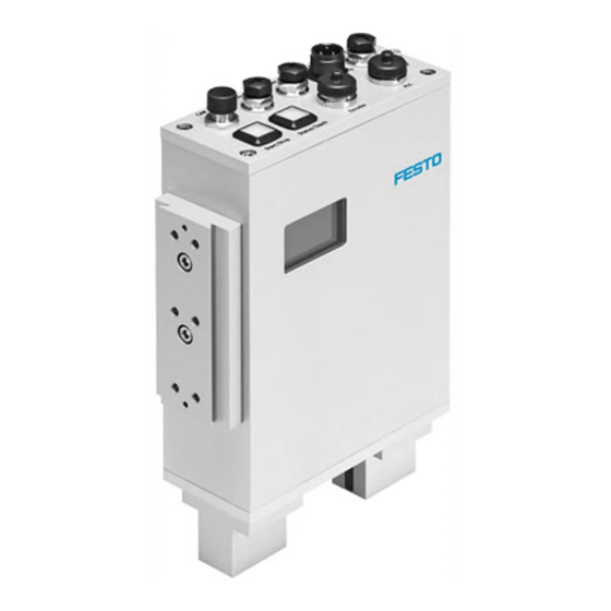
Buffer/Feeder Actuators Ethernet Encoder Fig. 3/1: The I/O module of the CHB-C-N Function – Connection of 1 buffer zone sensor for controlling the flow of parts to the next machine – 24 V power outputs for controlling the supply system (small... - Page 60 3. I/O module Power supply Observe the instructions on supplying power to external com ponents in chapter 2.3.3 and chapter 3.6. For electrical properties of the I/O signals, see Technical data (appendix A.5). Festo GDCA-CHB-C-N en 1508e English...
-
Page 61: Actuators
If a part has already passed an actuator position before the assignment according to the inspection result is present, the CHB-C-N changes to its error state. Despite an apparently correct configuration of the actuator positions, it may be the case that good parts are ejected at the defective parts actuator. - Page 62 Kon, if connected) deviates from the actually performed sep aration of parts. Controlling the actuators Note If there is a failure in the power supply to the CHB-C-N or to the actuators when the transporting device is running, this can result in: Parts passing the actuator positions unchecked •...
- Page 63 – Defective or foreign part If the CHB-C-N recognizes an inspection part as a good part, the signal actuator 3 will be set from the rest potential 0 V to + 24 V DC and the good part will be output at the end of the transporting device.
-
Page 64: Buffer/Feeder
Buffer Buffer zone sensor 1 Do not connect Tab. 3/2: BUFFER/FEEDER connector socket Direct connection can also be made with a Festo Duo cable (accessories è www.festo.com/catalogue). Identification of the Duo cable Signal x Buffer zone sensor 1 Signal x + 1... - Page 65 If the buffer zone sensor is triggered in the run mode, “BUF” will appear in the display. Fig. 3/2: Buffer zone full BUF signals the status “Buffer zone full” • If the buffer zone is emptied, “BUF” will disappear from • the display Festo GDCA-CHB-C-N en 1508e English...
- Page 66 Buffer zone empty: 1.0 s (0.1 s ... 180 s) Sensor type The CHB-C-N is factory preset for use with a buffer zone sensor, the sensor output of which lies at a potential of 0 V (i.e. no conveyed part in front of the sensor) in the rest state.
- Page 67 30 s has expired, the small parts conveyor will be switched off; the transporting device still runs. factory presetting to be set with CheckKon Information on dimensioning the buffer zone can be found in chapter 1.5. 3-11 Festo GDCA-CHB-C-N en 1508e English...
-
Page 68: Ethernet Interface
If in doubt, ask your network administrator whether cor • responding band widths are available for you or what an optimum network structure for you should look like. Comply with the necessary system requirements. • 3-12 Festo GDCA-CHB-C-N en 1508e English... - Page 69 PC must be fulfilled. The network properties of the device can be adapted using the Festo Field Device Tool (FFT). Factory setting of the IP ad dress: 192.168.2.20. Signal...
- Page 70 3. I/O module Status Description Green (speed) 10Base-T 100Base-TX Yellow (Link) No Link Link Traffic Tab. 3/4: LED function 3-14 Festo GDCA-CHB-C-N en 1508e English...
- Page 71 Original cable Crossover cable e.g. NEBC-D12G4-KS-3-R3G4, Order no. 8031121 Cable coupling Fig. 3/3: Direct connection to the PC 3-15 Festo GDCA-CHB-C-N en 1508e English...
-
Page 72: Encoder
3. I/O module Encoder Festo generally recommends connecting an encoder. Note Only use a screened cable. • Connect the screening at both ends to earth potential • with low impedance. If high demands are placed on the accuracy of the length of... - Page 73 Fig. 3/4: Belt speed Press and hold the Status/Teach button in the RUN mode. • Cnv. Speed: Belt speed (203) shows the current speed of • the conveyor belt in mm/s (only in Encoder mode) 3-17 Festo GDCA-CHB-C-N en 1508e English...
-
Page 74: Plc
= HIGH Tab. 3/6: Reference voltage Load voltage Consumers can be supplied with power via pin 4 (GND) and pin O/7 (+24 V) under the following condition: Load output O/7 with maximum 700 mA. • 3-18 Festo GDCA-CHB-C-N en 1508e English... - Page 75 Control of the small parts conveyor (e.g. up stream feeder bowl) Operating status, control of the transporting O/21 device (e.g. conveyor belt) Error messages Fault status 1: “Error” status signal O/17 Configurable allocation Tab. 3/7: I/O functions of the PLC interface 3-19 Festo GDCA-CHB-C-N en 1508e English...
- Page 76 – Logical “0”: U < 5 V Outputs: – Max. current load per channel: 700 mA – Max. resultant current of all outputs: 0.9 A – PNP switching Tab. 3/9: Electrical properties of the PLC interface 3-20 Festo GDCA-CHB-C-N en 1508e English...
-
Page 77: Start/Stop Mode
3. I/O module 3.6.1 Start/Stop mode The controller of the CHB-C-N requires that – the power supply for the CHB-C-N is applied – the boot procedure has been completed (O/7 = HIGH) – the signals for selecting the inspection program are stable (see chapter 3.6.2). - Page 78 < 1 s rs = remote start = min 0.1 s ts = type select = duration of the switch-on delay d = delay Tab. 3/11: Pulse-time diagram: Timing requirement to the higher-order controller 3-22 Festo GDCA-CHB-C-N en 1508e English...
-
Page 79: Selection Of The Check Program
3. I/O module 3.6.2 Selection of the check program For automatic changing of the check program via the PLC: Switch the CHB-C-N to the stop status. • Set the signals at the inputs in accordance with the binary • coding of the desired check program. (see following tables). - Page 80 Check program change 1 > 4 Type 1 Type 4 Pin I/20 Type select 0 Pin I/5 Type select 1 Pin I/6 Remote Start min 0.1 s Pulse-time diagram: Check program change 1 } 4 Tab. 3/13: 3-24 Festo GDCA-CHB-C-N en 1508e English...
- Page 81 Number of buffer zone sensors=1 z External signal input activated=no Ext. type Ext. type Ext. type Ext. type selection selection selection selection bit 0 bit 1 bit 2 bit 3 Tab. 3/14: Maximum number of check programs 3-25 Festo GDCA-CHB-C-N en 1508e English...
- Page 82 The Checkbox can internally store up to 256 check programs. Only the first 16 check programs can be selected via the PLC interface. Access to all 256 check programs is only possible in CheckKon via system parameters. 3-26 Festo GDCA-CHB-C-N en 1508e English...
- Page 83 HIGH HIGH HIGH HIGH HIGH HIGH HIGH HIGH HIGH HIGH HIGH HIGH HIGH HIGH HIGH HIGH HIGH HIGH HIGH HIGH HIGH HIGH HIGH HIGH HIGH HIGH Tab. 3/15: Binary coding of check program 1..16 3-27 Festo GDCA-CHB-C-N en 1508e English...
-
Page 84: Counting Function
When the CHB-C-N is switched off (operating voltage off ), counting will be interrupted. The current counter readings will be deleted. When the CHB-C-N is switched on, a new counting cycle is started. After stopping or switching off the CHB-C-N, remove all •... - Page 85 The current counter reading and the target counter reading can be displayed by pressing the Teach/Status button while the device is in the Run mode. Fig. 3/6: Counter reading 3-29 Festo GDCA-CHB-C-N en 1508e English...
- Page 86 • Target Target counter reading (3) • In order to start a new counting procedure, the CHB-C-N re quires the signal “Start new cycle” from the higher-order con troller. In order to start the counting cycle, the signal LOW>HIGH>LOW must be present at input I/18.
- Page 87 Pin I/18 Reset Start new counting cycle > 15 ms Pin O/22 Preselected counter read ing reached sc = start counting cycle r = reset Tab. 3/17: Pulse-time diagram: Control of the counting pro cedure 3-31 Festo GDCA-CHB-C-N en 1508e English...
-
Page 88: Actuators
Input I/19 is provided on the PLC connector to monitor the supply of pneumatic actuators. An “External error”, which switches the Checkbox to its error state, can be triggered via this input, e.g. via a pressure sensor. 3-32 Festo GDCA-CHB-C-N en 1508e English... - Page 89 This delay arises due to a (long) distance between the actuator positions. 3-33 Festo GDCA-CHB-C-N en 1508e English...
-
Page 90: Buffer Zone Sensors/Small Parts Conveyor
After starting, the Checkbox triggers the actuator for sorting out the defective parts. This is to ensure that no (unchecked) parts are located on the transporting device. This results in a delay of a few seconds between the external Start command 3-34 Festo GDCA-CHB-C-N en 1508e English... - Page 91 Tab. 3/20: Pulse-time diagram: Control of the small parts conveyor Buffer zone sensors With CheckKon, the CHB-C-N can be configured for operation either with one buffer zone sensor or for switching delay of the small parts conveyor with two buffer zone sensors (Fig.
- Page 92 Factory presetting To be set with CheckKon with buffer zone monitoring – with one sensor: Sensor 1 – with two sensors: Sensor 2 Tab. 3/21: Sensor function 3-36 Festo GDCA-CHB-C-N en 1508e English...
-
Page 93: Fault Messages
3.6.7 Locking the control panel Via pin I/11, the buttons Start/Stop and Status/Teach on the CHB-C-N can be locked against unauthorized actuation. The Checkbox can then be started or stopped only via pin I/6. A change to the TEACH mode is not possible. - Page 94 • Stop button or the Teach/Status button is pressed. Teach Teach button lock (--) is deactivated • The display appears for 1.5 s and then reverts back to the • original operating status display 3-38 Festo GDCA-CHB-C-N en 1508e English...
- Page 95 The Status/Teach button remains locked until the function is switched off again in the CheckKon menu [View] [System parameter]: Z System Z Operating modes z Lock the Teach button = Off. 3-39 Festo GDCA-CHB-C-N en 1508e English...
- Page 96 3. I/O module 3-40 Festo GDCA-CHB-C-N en 1508e English...
-
Page 97: Teach Parts
Teach parts Teach parts Chapter 4 Festo GDCA-CHB-C-N en 1508e English... - Page 98 ......4.2.2 Observing the scatter of characteristics ..... 4-10 Festo GDCA-CHB-C-N en 1508e English...
-
Page 99: Teach Parts
As standard during the Teach procedure, the parts are sorted out at the first actuator position. This is to ensure that no sample parts are transported by mistake to the next machine in the process. Festo GDCA-CHB-C-N en 1508e English... - Page 100 In the diagnostic mode the Checkbox transmits additional information via the diagnostic interface. Do not operate the Checkbox in diagnostic mode with • the full parts rate. In this way you can prevent parts from passing the actua tor positions unchecked. Festo GDCA-CHB-C-N en 1508e English...
-
Page 101: The Teach Procedure
Scan the sample parts of the check program one after the • other in all intended orientations (max. 8), as described below. Scanning sample parts in orientation 1 1. Press the Status/Teach button to switch the Checkbox to the Teach mode. Festo GDCA-CHB-C-N en 1508e English... - Page 102 Teach LOCK If “Teach LOCK” is shown in the display, it means the Status/Teach button is locked and the Teach mode cannot be started. The CHB-C-N remains in its stop status. Switch off the Teach button lock with CheckKon: [View] •...
- Page 103 After saving, carry out the following steps: Check the Teach procedure in the test mode with regard • to orientation and quality as described in chapter 5. Keep a record of your work. • Festo GDCA-CHB-C-N en 1508e English...
- Page 104 4. Teach parts Register the next check program in a further Teach procedure: Address the next check program via the PLC inputs • (chapter 3.6.2). Repeat all steps as from point 1. • Festo GDCA-CHB-C-N en 1508e English...
-
Page 105: Positioning The Sample Parts
Make sure in particular that orientation 1 (target orienta • tion) differs clearly in at least one feature from all the other orientations. Festo GDCA-CHB-C-N en 1508e English... -
Page 106: Observing The Scatter Of Characteristics
> 30 Large scatter of at least one feature A detailed description of the computational algorithm of the scatter of characteristics can be found in Appendix A.3.2. Tab. 4/1: Sctr value (scatter of characteristics) 4-10 Festo GDCA-CHB-C-N en 1508e English... -
Page 107: Checking Parts
Checking parts Checking parts Chapter 5 Festo GDCA-CHB-C-N en 1508e English... - Page 108 ........5-12 Festo GDCA-CHB-C-N en 1508e English...
-
Page 109: Checking Parts
Prog: Check program number (3) • Check program name (Name 1) indicates the number • and name of the selected check program OK indicates the overall test result (GOOD) in text form • Festo GDCA-CHB-C-N en 1508e English... - Page 110 Protect the Teach data against undesired modification: • – By using the control panel lock (see chapter 3.6.7) – With the CheckKon software: [View] [System parameter] Z System Z Operating modes ... z Lock the Teach button = On. Festo GDCA-CHB-C-N en 1508e English...
-
Page 111: Test Mode
6. Use the sample parts to check the sample parts with re gard to their grading. If you have also tested faulty parts, check whether these have actually been recognized as defective. Festo GDCA-CHB-C-N en 1508e English... - Page 112 If the quality check and the position recognition for the parts assortment is not satisfactory, you can use additional operating parameters and tools with CheckOpti, in order to optimize the test results. Please consult your local Festo Sales Engineer. Festo GDCA-CHB-C-N en 1508e English...
- Page 113 8. Press the Start/Stop button to switch the Checkbox to the Stop status. 9. Conclude the diagnostic mode. Close CheckKon (and CheckOpti). Festo GDCA-CHB-C-N en 1508e English...
-
Page 114: Influence Of Tolerance
Tol.: The tolerance setting mode can be accessed by • pressing and holding the Start/Stop button. The current tolerance value (10 %) is displayed. Prog: Check program number (1) indicates the number • and name of the selected check program Festo GDCA-CHB-C-N en 1508e English... - Page 115 Recommendation for setting steps at least 1 % 3. Release the Start/Stop button when the desired value has been set. The selected value will be added automatically to the data of the check program and saved. Festo GDCA-CHB-C-N en 1508e English...
- Page 116 Vary the tolerance so that the following inspection • part deviation is shown when the limit sample part is scanned: ‹ 100 limit sample part “good” › 100 limit sample part “defective” 5-10 Festo GDCA-CHB-C-N en 1508e English...
-
Page 117: Evaluation Of The Test Results
Defective part The greater the value, the less the inspection part corresponds to the sample parts. Display range: 0 to 999 Tab. 5/1: Inspection part deviation 5-11 Festo GDCA-CHB-C-N en 1508e English... -
Page 118: Checking The Orientation
5. Checking parts 5.4.2 Checking the orientation The Checkbox ascertains during the test procedure whether the orientation of the last scanned inspection part can be assigned to the orientations of the sample part. 5-12 Festo GDCA-CHB-C-N en 1508e English... -
Page 119: Maintenance
Maintenance Maintenance Chapter 6 Festo GDCA-CHB-C-N en 1508e English... - Page 120 ........Festo GDCA-CHB-C-N en 1508e English...
- Page 121 Note Damage to the glass surfaces can result in operative mal functions of the Checkbox. Consult your Festo Service in case of damage. • The Checkbox has been designed for rough industrial envir onments and is distinguished by its high reliability, robust structure and long service life.
-
Page 122: Cleaning
With clean, unlubricated compressed air • With a soft, moist cloth and non-abrasive cleaning agents. • You will then avoid damage which could lead to malfunc tioning of the Checkbox. Festo GDCA-CHB-C-N en 1508e English... -
Page 123: Replacing The Prism Module
Replace the prism module as follows: Fig. 6/1: Prism module 1. Remove the screws (3). Leave the sealing rings in place. Festo GDCA-CHB-C-N en 1508e English... - Page 124 Then screw the prism in place on the illumination side. 7. Screw the prism support in place on the sensor side. 8. Check the line display with CheckKon. If the line display is not optimal: Festo GDCA-CHB-C-N en 1508e English...
- Page 125 6. Maintenance 9. Loosen the screws on the sensor side slightly. 10. Twist and/or move the prism support slightly. 11. Repeat steps 7 and 8. Festo GDCA-CHB-C-N en 1508e English...
- Page 126 6. Maintenance Festo GDCA-CHB-C-N en 1508e English...
- Page 127 Technical appendix Technical appendix Appendix A Festo GDCA-CHB-C-N en 1508e English...
-
Page 128: A. Technical Appendix
........... . A-23 Festo GDCA-CHB-C-N en 1508e English... -
Page 129: Technical Appendix
Checkbox runs in the diagnostic – with CheckKon: Switch from tion of the actuators is not mode the diagnostic mode to the correct. operating mode, or – Conclude CheckKon/ CheckOpti. Tab. A/1: Faults and remedies Festo GDCA-CHB-C-N en 1508e English... -
Page 130: Fault Messages And Warnings
(see following table): Note If fault messages and warnings are deactivated, undefined operating states and malfunctioning can occur in the event of a fault. Before deactivating, check whether additional measures are necessary for avoiding faults. Festo GDCA-CHB-C-N en 1508e English... - Page 131 – Jam of parts in front of the – If the glass surfaces are defective: Consult your Festo visual channel Service – Glass surface misted due to –...
- Page 132 Teach procedure, or – The nominal orientation is too similar to other orienta tions. Check program cannot be read/ – Delete the check program with the CheckKon software found. and repeat the Teach procedure Festo GDCA-CHB-C-N en 1508e English...
- Page 133 – Transgression of the max imum permissible resultant current at one of the outlet ports: Actuator, Buffer or PLC – Transgression of the max imum permissible resultant current of all outputs Tab. A/2: Error codes Festo GDCA-CHB-C-N en 1508e English...
- Page 134 – High fluctuations in temper – With CheckKon: Set the pic ing although the Checkbox ature e.g. between day and ture limits. functioned faultlessly the day night before. – Transporting device has been replaced. Tab. A/3: Other error states Festo GDCA-CHB-C-N en 1508e English...
-
Page 135: Status Displays On The Device
– RUN mode – TEACH mode Continuous green light Checkbox is ready to operate (Stop status) STATUS/TEACH Flashes yellow New part passes the camera START/STOP Flashes red Malfunction STATUS/TEACH Flashes yellow Tab. A/4: Illuminated pushbutton Festo GDCA-CHB-C-N en 1508e English... -
Page 136: Examples For Calculation Of The Features
³ T + Average value of the feature Band width Feature maximum Upper limit of the band width incl. tolerance max tol Feature minimum Lower limit of the band width incl. tolerance min tol Tolerance A-10 Festo GDCA-CHB-C-N en 1508e English... - Page 137 Band width of the conveyed part length Band width at 5 % tolerance Result: All conveyed parts with a length of 57 ... 68 mm are classified as good parts. The Checkbox ascertains appropri ate value ranges for each feature. A-11 Festo GDCA-CHB-C-N en 1508e English...
-
Page 138: Scatter Of Characteristics
The following values are taken from the example “Band width”: = 61.2 Average value of the length = 65 Length, maximum = 60 Length, minimum S + 65*60 100 % 61, 2 S + 8, 2 % A-12 Festo GDCA-CHB-C-N en 1508e English... -
Page 139: Inspection Part Deviation
“Band width”: = 61.2 Average value of the length = 56.94 Length, lower limit min tol = 61 Length, current value actual 61*61, 2 100 % 56, 94*61, 2 D + 4, 7 % A-13 Festo GDCA-CHB-C-N en 1508e English... - Page 140 “Band width”: = 61.2 Average value of the length = 68.06 Length, upper limit max tol = 64 Length, current value actual 64*61, 2 100 % 68, 06*61, 2 D + 40, 8 % A-14 Festo GDCA-CHB-C-N en 1508e English...
-
Page 141: Connections
Control of the supply system (small parts conveyor) Reference voltage for sensors Buffer zone sensor 1 Do not connect Tab. A/6: BUFFER/FEEDER connector socket Direct connection can also be made with a Festo Duo cable (accessories è www.festo.com/catalogue). A-15 Festo GDCA-CHB-C-N en 1508e English... - Page 142 Do not connect Tab. A/8: ACTUATORS connection socket Signal M12 Ethernet connection socket Transmitted data + Received data + Transmitted data – Received data – Metal covering Screening (shield) d-coded Tab. A/9: Ethernet connector plug A-16 Festo GDCA-CHB-C-N en 1508e English...
- Page 143 Actuator 2 Green OUT24_Act3 Actuator 3 Yellow GND_NT 0 V / reference voltage for buffer zone sensors Grey IN24_TypeSel1 External program selection: Bit 1 Pink IN24_Ext_Start Save the Start/Stop mode and the Teach data A-17 Festo GDCA-CHB-C-N en 1508e English...
- Page 144 Functions with a grey background have been deactivated at the factory and can be activated and adapted with CheckKon. The counting function and the special function “External sensor” cannot be used at the same time. Tab. A/11: PLC connector socket A-18 Festo GDCA-CHB-C-N en 1508e English...
- Page 145 Buffer zone sensor 1 I/12 I/13 Buffer zone sensor 2 If the counting function is deactivated, the output of actuator 4 is available at the PLC connection. Tab. A/12: Internal wiring of the connections A-19 Festo GDCA-CHB-C-N en 1508e English...
-
Page 146: Technical Data
– Internal fuse protection 4 A fuse Interfaces according to RS 485 specification – Connection for encoder Ethernet interface 100 MBit/s – Ethernet connection Observe chapter 2.2 “Mounting”, “Temperature” section Tab. A/13: Technical data: General A-20 Festo GDCA-CHB-C-N en 1508e English... - Page 147 – Max. resultant current of all outputs: 3 A Tab. A/15: Technical data: Electrical properties Camera and lighting 2048 pixels or 14 ìm * 14 ìm Resolution Line rate 1000 ... 8500 Hz Tab. A/16: Technical data: Camera and lighting A-21 Festo GDCA-CHB-C-N en 1508e English...
- Page 148 Rotationally symmetrical parts and pre-oriented parts of any shape Min. part length 1 mm Max. part length Dependent on belt speed and required resolution Part diameter 0.5 ... 25 mm Tab. A/17: Technical data: Features of conveyed parts A-22 Festo GDCA-CHB-C-N en 1508e English...
-
Page 149: Accessories
A. Technical appendix Accessories Please select the appropriate accessories from our catalogue (www.festo.com/catalogue). A-23 Festo GDCA-CHB-C-N en 1508e English... - Page 150 A. Technical appendix A-24 Festo GDCA-CHB-C-N en 1508e English...
- Page 151 Index Index Appendix B Festo GDCA-CHB-C-N en 1508e English...
-
Page 152: B. Index
............Festo GDCA-CHB-C-N en 1508e English... - Page 153 Internal wiring ....... . . A-19 Festo GDCA-CHB-C-N en 1508e English...
- Page 154 ........Festo GDCA-CHB-C-N en 1508e English...
- Page 155 ........Operating voltage ....... 2-16 Festo GDCA-CHB-C-N en 1508e English...
- Page 156 ........START/STOP ......2-20, 2-27, A-9 Festo GDCA-CHB-C-N en 1508e English...
- Page 157 ........2-27, A-4 Festo GDCA-CHB-C-N en 1508e English...
Need help?
Do you have a question about the CHB-C-N and is the answer not in the manual?
Questions and answers