
Subscribe to Our Youtube Channel
Related Manuals for FISCHER EA14D


Summary of Contents for FISCHER EA14D
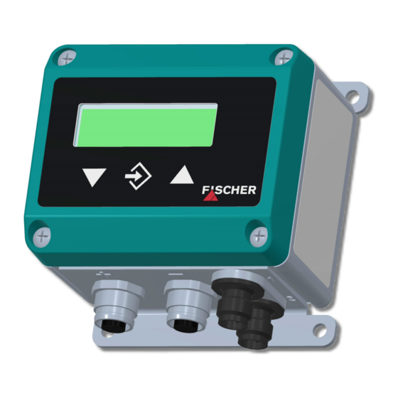
- Page 1 Operating manual EA14D Differential pressure evaluation unit with colour change LCD...
- Page 2 Great care was taken when compiling the texts and illustrations; Nevertheless, errors cannot be ruled out. The company FISCHER Mess- und Regeltechnik GmbH will not accept any legal responsibility or liability for this.
-
Page 3: Table Of Contents
FISCHER Mess- und Regeltechnik GmbH Table of contents Table of contents 1 Safety instructions ............................ 4 1.1 General .............................. 4 1.2 Personnel Qualification.......................... 4 1.3 Risks due to Non-Observance of Safety Instructions ................ 4 1.4 Safety Instructions for the Operating Company and the Operator............ 4 1.5 Unauthorised Modification ........................ 4... -
Page 4: Safety Instructions
1 | Safety instructions FISCHER Mess- und Regeltechnik GmbH 1 Safety instructions 1.1 General This operating manual is an integral part of the product and therefore needs to be kept close to the instrument in a place that is accessible at all times to the re- sponsible personnel. -
Page 5: Safe Working Practices For Maintenance And Installation Work
FISCHER Mess- und Regeltechnik GmbH Safety instructions | 1 1.7 Safe working practices for maintenance and installation work The safety instructions given in this operating manual, any nationally applicable regulations on accident prevention and any of the operating company's internal work, operating and safety guidelines must be observed. -
Page 6: Product And Functional Description
2 | Product and functional description FISCHER Mess- und Regeltechnik GmbH 2 Product and functional description 2.1 Delivery scope • 1 x differential pressure evaluation unit EA14D • 2 x pressure transmitter incl. connection cable • Operating Manual – Analysis unit –... -
Page 7: Equipment Versions
FISCHER Mess- und Regeltechnik GmbH Product and functional description | 2 2.5 Equipment versions EA14 D... H ... EA14 D... M ... Supply Switch output Type plate Wiring diagram Process connection Fig. 2: Equipment versions 2.5.1 Assembly types Standard Wall mounting... - Page 8 2 | Product and functional description FISCHER Mess- und Regeltechnik GmbH 2.5.2 Type plate Order code Techn. Data Item no. EA14D006MA4KWCMW Basic measuring range 0 ... 6 bar Input signal 0 ... 20 mA Output signals Δ P, P1/P2 0 ... 20 mA...
-
Page 9: Assembly
FISCHER Mess- und Regeltechnik GmbH Assembly | 3 3 Assembly 3.1 General The device is designed for installation onto flat assembly plates. For screw con- nection to the assembly plate, the device features four assembly bores on its back, which can be used for Ø 3.5 mm tapping screws. Optionally, the device can be delivered with a wall-mounting plate, a front-mounted panel set or an ad- apter for assembly of the support rail. -
Page 10: Electrical Connection (Auxiliary Energy, Output Signals)
3 | Assembly FISCHER Mess- und Regeltechnik GmbH 3.2.2 Plug connector DIN EN 175301-803 A The plug assignment is identical for both inputs. The plugs are marked with (+) and (-). Fig. 6: Process connection PIN Signal (2L pressure transmitter) Pressure transmitter signal and supply (+) - Page 11 FISCHER Mess- und Regeltechnik GmbH Assembly | 3 3.3.1 Plug 1: Auxiliary energy, analogue output Mains adapter EA14D + (~) 24 V AC/DC - (~) +Out1 +Out2 230 V AC Plug 1 Output1 Output2 Fig. 8: Analogue output connection PIN Signal...
-
Page 12: Start-Up
4 | Start-up FISCHER Mess- und Regeltechnik GmbH 4 Start-up 4.1 General All electrical supply, operating and measuring lines, and the pressure connec- tions must have been correctly installed before commissioning. All supply lines are arranged so that there are no mechanical forces acting on the device. -
Page 13: Keyboard
FISCHER Mess- und Regeltechnik GmbH Start-up | 4 (b) Operating mode 2-channel In this operating mode, the first channel is assigned to the differential pressure (P+). The second channel of the pressure measurement (P-). According to this assignment, the measured values and the channel numbers (ch1) and (ch2) are shown. -
Page 14: Menu Levels
4 | Start-up FISCHER Mess- und Regeltechnik GmbH If a parameter can be changed, the display flashes. The change is made via the þ ÿ û buttons . The value is saved with the button To leave a menu level or the entire menu, select the parameter "Menu level... - Page 15 FISCHER Mess- und Regeltechnik GmbH Start-up | 4 4.5.1 Menu Level Switch points (2SP) Parameter name Description Value range SP1 On Switch point 1 On MBA-50% … MBE+50% SP1 Off Switching point 1 off MBA-50% … MBE+50% SP1 delay Switching point 1 delay 0…1800 s...
- Page 16 4 | Start-up FISCHER Mess- und Regeltechnik GmbH Assignment SP is used to define the input to which the contacts are assigned. The following options are available: • Channel 1 Both contacts are assigned to channel 1. • Channel 1, channel 2 A contact is assigned to every channel.
- Page 17 FISCHER Mess- und Regeltechnik GmbH Start-up | 4 The display only stops showing zero when the measurement leaves the set win- dow. When reaching double the value, the measured value and the reading match again. This avoids jumps in the display.
- Page 18 4 | Start-up FISCHER Mess- und Regeltechnik GmbH The output signals of the transmitter primarily depend on the measured input variables (channel 1 or channel 2). However, you have the option of adjusting the output signals to a large extent to suit your requirements.
- Page 19 FISCHER Mess- und Regeltechnik GmbH Start-up | 4 (b) Operating mode 2-channel There are two output signals available. Output 1 (Sig1) is permanently assigned to the pressure at input (P+) and output 2 (Sig2) is permanently assigned to the pressure at input (P-).
- Page 20 4 | Start-up FISCHER Mess- und Regeltechnik GmbH Square rooted function Here, the input signal is square rooted before being sent to the display and the output. A free unit can be defined for the display. To do this, the start and end of the display range and the number of decimal points are defined.
- Page 21 FISCHER Mess- und Regeltechnik GmbH Start-up | 4 NOTICE Number of value pairs If the number of value pairs is changed, the table is initialised again and the ex- isting values are deleted. Value pair +14,6 mbar +8,6 % +0,0 ...
- Page 22 4 | Start-up FISCHER Mess- und Regeltechnik GmbH 4.5.7 Menu Level Display The Display menu level is a variable menu whose appearance depends on the value of the colour parameter. In addition to the various colours for the back- ground lighting, there are also two auto-functions with colour switching avail- able.
- Page 23 FISCHER Mess- und Regeltechnik GmbH Start-up | 4 Auto1: Colour-change red to green If parameter Colour is set to Auto 1: red-green, the menu changes as follows: Parameter name Description Value range Assignm. switch. Assignment switching Channel 1, channel 2 Red-Gr.
- Page 24 4 | Start-up FISCHER Mess- und Regeltechnik GmbH Auto2: Colour-change red-yellow-green If the parameter Colour is set to Auto 2: red-yellow-green, the menu changes as follows: Parameter name Description Value range Assignm. switch. Assignment switching Channel 1, channel 2 Red-Yell.switch.
- Page 25 FISCHER Mess- und Regeltechnik GmbH Start-up | 4 The parameter Colour is set to Auto2. Only the green, yellow and red ranges Example are required here. To fade out the lower ranges red and yellow, the switch thresholds "red-yellow switching" and "yellow-green switching" are set to the start of the measuring range.
- Page 26 4 | Start-up FISCHER Mess- und Regeltechnik GmbH The password needs to be set if the user presses the button in normal mode to enter the menu. If a wrong password is entered, the system automatically jumps back to normal mode again. If no password is active, the display immediately jumps to the menu.
-
Page 27: Servicing
FISCHER Mess- und Regeltechnik GmbH Servicing | 5 5 Servicing 5.1 Maintenance The instrument is maintenance-free. We recommend the following regular in- spection to guarantee reliable operation and a long service life: • Check the function in combination with downstream components. -
Page 28: Technical Data
FISCHER Mess- und Regeltechnik GmbH 6 Technical data 6.1 Generalities The stated technical data only refer to the differential pressure evaluation unit EA14D and never take into account the properties of the connected pressure transmitter. 6.2 Input variables Analogue input... -
Page 29: Measurement Accuracy
FISCHER Mess- und Regeltechnik GmbH Technical data | 6 6.4 Measurement accuracy Maximal Typical Measurement deviation 0.1 % FS <0.05 % Temperature drift Span 0.1 %FS/10K <0.025 %FS/10K Zero point 0.1 %FS/10K <0.025 %FS/10K Characteristic curve deviation (non-linearity and hysteresis) at 25°C and rated... -
Page 30: Construction Design
6 | Technical data FISCHER Mess- und Regeltechnik GmbH 6.8 Construction design Process connection 2 x 5-pin round plugs M12 (female) for ex- ternal pressure transmitters or 2 x 4-pin standard plug DIN EN 175 301-803-A (female) with 1 m cable... - Page 31 FISCHER Mess- und Regeltechnik GmbH Technical data | 6 6.8.2 Dimensional drawings Wall mounting plate 70.5 61.5 M12 plug M12 Buchse plug 2 plug 1 Standard plug DIN 175 301-803 with 1 m cable Fig. 19: Dimensional picture 6.8.3 Wall mounting...
- Page 32 6 | Technical data FISCHER Mess- und Regeltechnik GmbH 6.8.4 Assembly of the mounting rails Adapter element 61.5 Fig. 21: Adapter element TS35 TS35 TS15 TS32 Fig. 22: Mounting rails options 32 / 36 BA_EN_EA14D...
- Page 33 FISCHER Mess- und Regeltechnik GmbH Technical data | 6 6.8.5 Installation of front panel panel mounting set Wall thickness 3 ... 5 mm Front plate 92 ± 0.2 90 ± 0.2 Panel cut-out Fig. 23: Installation of front panel BA_EN_EA14D 33 / 36...
-
Page 34: Order Codes
7 | Order codes FISCHER Mess- und Regeltechnik GmbH 7 Order codes Code no. 10 11 12 Type [3.4] Measuring range (differential pressure) 0 … 2.5 bar 0 … 6 bar 0 … 10 bar 0 … 16 bar 0 … 25 bar 0 …... -
Page 35: Accessories
FISCHER Mess- und Regeltechnik GmbH Order codes | 7 [12] Assembly Attachment boreholes on rear side (standard) Wall mounting Panel mounting set Assembly of the mounting rails 7.1 Accessories Order no. length 4-pin M12 Connection cable for switching outputs 06401993... -
Page 36: Eu Declaration Of Conformity
8 | EU Declaration of Conformity FISCHER Mess- und Regeltechnik GmbH 8 EU Declaration of Conformity Fig. 24: CE_DE_EA14D 36 / 36 BA_EN_EA14D...
Need help?
Do you have a question about the EA14D and is the answer not in the manual?
Questions and answers