
Related Manuals for Metso L12 Series


Summary of Contents for Metso L12 Series
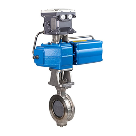
- Page 1 ® NELDISC Metal seated high performance triple eccentric disc valve Series L12 Installation, Maintenance and Operating Instructions...
-
Page 2: Table Of Contents
2 L12 71 en Table of Contents GENERAL ..............3 Scope of the manual ...........3 Valve construction ..........3 Valve markings ............3 Technical specifications ........4 Valve approvals .............4 CE marking ..............4 Recycling and disposal ........4 Safety precautions ..........4 TRANSPORTATION, RECEPTION AND STORAGE ..............5 INSTALLATION .............5 General ..............5 Mounting into the pipeline....... -
Page 3: General
Body material Shaft material Valve construction Trim material L12 series valve is a wafer type metal seated, full bore triple Seat material eccentric disc valve. The valve body is one-part in sizes DN Maximum operating temperature 80–600 and the sizes DN 700–1400 have a bolted clamp Minimum operating temperature ring. -
Page 4: Technical Specifications
The valve may produce noise in the pipeline. The noise and disposal against a fee. level depends on the application. It can be measured or calculated using Metso Nelprof computer program. Observe the relevant work environment regulations on noise emission. -
Page 5: Transportation, Reception And Storage
2 L12 71 en TRANSPORTATION, RECEPTION AND Do not attempt to correct pipeline misalignment by means STORAGE of flange bolting. Check the valve and the accompanying devices for any It may be necessary to firmly support the pipeline to pro- damage that may have occurred during transport. - Page 6 2 L12 71 en will open unexpectedly due to pre-stressed spring package. 3.2.1 Mounting options This may cause significant harm to people and material X Flange bolts pass the neck of the body around the valve. SB Stud bolts at the neck of the body In valves with certain nominal sizes some flange bolts do not pass the valve body.
-
Page 7: Actuator
The inspection and maintenance intervals can be specified Insulation limit together with your local Metso experts. During this periodic inspection the parts detailed in the Spare Part Set should be replaced. Time in storage should be included in the inspection interval. - Page 8 2 L12 71 en The gland packing (20) must be changed if leakage occurs 5.3.2 Live-loaded packing even after the hex nuts (25) have been tightened. Make sure the valve is not pressurized. The actuator needs not be removed if the gland packing is ...
-
Page 9: Replacing The Seat Ring, Sizes Dn 700-1400
2 L12 71 en Table 5 Tightening of live-loaded gland packing Compression (h –h ) mm Spring set Size Thread Packing ring material Graphite + DN / NPS M, UNC PTFE PTFE 80 / 3 M8, 5/16 100 / 4 M8, 5/16 125 / 5 M8, 5/16... -
Page 10: Assembling The Valve
2 L12 71 en NOTE: Use only pins supplied by the manufacturer! NOTE: The pins must be pressed with enough force to deform them so that the connection will be free from backlash. Fig. 15 Protecting the disc during disassembly and assembly ... -
Page 11: Detaching And Mounting The Actuator
2 L12 71 en DETACHING AND MOUNTING THE Table 8. Bushing dimensions ACTUATOR Outer dim. Inner dim. Height Actuator (mm) (mm) (mm) General EC/EJ05 24,5 12,5 EC/EJ07 24,5 16,5 32,75 CAUTION: EC/EJ10 24,5 20,5 When handling the valve or the valve package, bear in mind its weight! 6.2.2 Detaching B series actuators... - Page 12 2 L12 71 en Stop screw for Closing pressure closed position Stop screw for open position Opening Loctite 225 or pressure similar Fig. 23. Actuator connections Fig. 20. Cone bushing installation normal position (the mounting position shown in Fig. 21). Checking is important, as the actuator shaft drops down slightly when the screw is tightened.
-
Page 13: Detaching And Mounting The Other Actuator Types
Protect NOTE: the joint surfaces from corrosion, e.g. with Cortec VCI Metso accepts no responsibility for compatibility of actua- 369. tors not installed by Metso. If a bushing is required between the actuator shaft bore and the valve shaft, mount it first in the actua- 6.5.3... - Page 14 2 L12 71 en 6.5.7 Spring-return cylinder actuator B1JA Stop screw for the closed position Spring-to-open The actuator being unpressurized the valve is open. Unscrew the close limit stop screw (actuator hous- ing). Apply tabulated (Table 11) shut-off pressure Pc to the air connection at the cylinder bottom end against the spring force to close the valve.
-
Page 15: Tools
2 L12 71 en 6.5.10 Hand lever RH TOOLS No special tools are needed for servicing the valve. How- Mount the hand lever on the valve, but do not fasten ever, we recommend an extractor for removing the actua- hex screws (A). - Page 16 2 L12 71 en Table 12 Series L12, closing torques...
- Page 17 2 L12 71 en Table 11 Continued...
-
Page 18: Exploded View And Parts List
2 L12 71 en EXPLODED VIEW AND PARTS LIST Charge number ID number 26 10 18 16 Mgf number DN 700 - 1400 DN 80 - 600 Item Description Spare part category Body Clamp ring Disc (sizes DN 700–1400) Seat ring (sizes DN 700–1400) Gland Blind flange Drive shaft (sizes DN 700–1400) -
Page 19: Dimensions And Weights
2 L12 71 en DIMENSIONS AND WEIGHTS SIZE 500 - 1000 / 20" - 40" SIZES 80,100,125, / 3", 4", 5" ø O ø B SIZES 150-800 / 6" - 32" SIZES 900, 1000 / 36", 40" Dimensions, mm Thread Type øB L12A 80... - Page 20 2 L12 71 en Dimensions, mm L12 - M Type øZ øB Dimensions, in Type 9.49 7.28 2.56 2.05 6.30 9.49 7.28 2.56 2.05 7.87 11.97 9.25 3.46 2.80 12.40 15.94 12.01 3.66 3.39 15.75 17.95 13.62 4.02 4.13 19.69 20.87 15.24 4.88...
- Page 21 2 L12 71 en L12 - B1C/B1J STANDARD MOUNTING POSITION 1/4 NPT 1/4 NPT øB Dimensions, mm Type B1C6 B1C9 B1C11 B1C13 B1C17 B1C20 B1C25 1040 B1C32 1330 B1C40 1150 1660 B1C50 1350 1970 Dimensions, in Type B1C6 3.54 10.24 15.75 1.42 11.14...
-
Page 22: Type Code
2 L12 71 en TYPE CODE NELDISC® HIGH PERFORMANCE TRIPLE ECCENTRIC DISC VALVE, series L12 PRODUCT SERIES Wafer type, full bore, metal-seated Face-to-face lenght acc. to API 609 PRESSURE RATINGS Body rating DN 80–125: PN 50 / ASME 300 DN 150–600: PN 25 / ASME 150 Maximum shut-off pressure DN 80–125 Ps = 25 bar (ASME 150), welded clamp ring... - Page 23 2 L12 71 en...
- Page 24 2 L12 71 en Metso Flow Control Inc. Europe, Vanha Porvoontie 229, P.O. Box 304, FI-01301 Vantaa, Finland. Tel. +358 20 483 150. Fax +358 20 483 151 North America, 44 Bowditch Drive, P.O. Box 8044, Shrewsbury, M A 01545, USA. Tel. +1 508 852 0200. Fax +1 508 852 8172 South America, Av.
Need help?
Do you have a question about the L12 Series and is the answer not in the manual?
Questions and answers