
Related Manuals for Metso XT/XA Series


Summary of Contents for Metso XT/XA Series
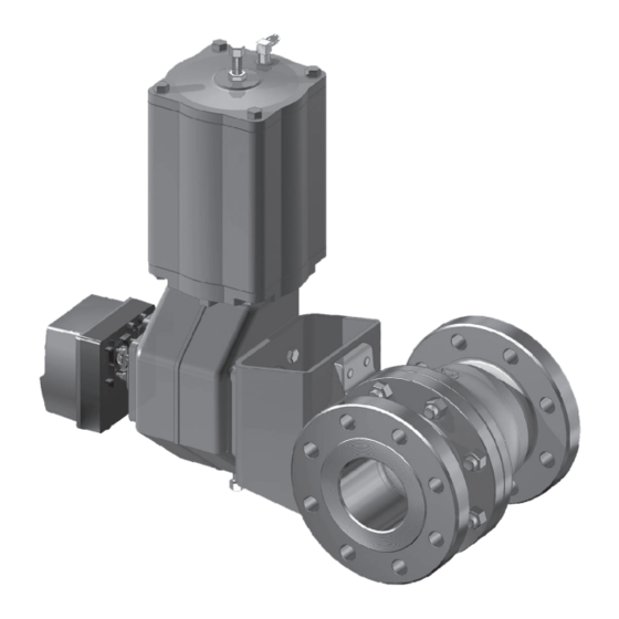
- Page 1 SEAT SUPPORTED BALL VALVES Series XT/XA and XB/XC Installation, Maintenance and Operating Instructions...
-
Page 2: Table Of Contents
..............15 Installing the B1C-series actuator ....15 Installing the B1J-series actuator ....15 Installing other than Metso actuators ..16 READ THESE INSTRUCTIONS FIRST! These instructions provide information about safe handling and operation of the valve. If you require additional assistance, please contact the manufacturer or manufacturer’s representative. -
Page 3: General
H or G Valve description seat XT/XA series valves are full bore and XB/XC series valves are reduced bore flanged ball valves. The valves are either metal or soft seated. Valves have two-piece bodies with bolted body joints, except the bodies of the 3", 4" and 6"... -
Page 4: Technical Specifications
(50 bar/750 psi) at ambient temperature Model (1) (2) (5) T (°C) Fig. 7 Maximum operational pressure differential, metal- MADE BY METSO AUTOMATION ATTENTION : READ INSTRUCTIONS BEFORE INSTALLATION OR SERVICING. CONTACT METSO FIELD SYSTEMS FOR COPY. BODY SHAFT T max MAX. OPER. RATING TYPE... -
Page 5: Valve Certifications
Beware of noise emission! The valve may produce noise in the pipeline. The noise level depends on the application. It can be measured or calculated using the Metso Nelprof computer program. Observe the relevant work environment regulations on noise emission. -
Page 6: Storage
1 X 78 en TRANSPORTATION, RECEPTION AND NOTE: STORAGE Use screws, nuts, bolts and gaskets equivalent to the fas- tenings used elsewhere in the pipeline. Center the flange Check the valve and the accompanying device for any dam- gaskets carefully when fitting the valve between flanges. age that may have occurred during transport. -
Page 7: Actuator
Fig. 15 Insulation of the valve significantly help to prevent unplanned downtime and in real terms reduce the total cost of ownership. Metso recom- Actuator mends inspecting the valves at least every five (5) years. The inspection and maintenance interval depends on the actual NOTE: application and process condition. -
Page 8: Repairing A Jammed Or Stiff Valve Without Removing It From The Pipeline
1 X 78 en The gland packing (69) must be changed if leakage occurs even after the hex nuts (18) have been tightened. The V- ring gland packing must be tightened with care because excess force may damage the V-rings. ... -
Page 9: Removing The Valve From The Pipeline
1 X 78 en Close and detach the actuator pressure supply and disconnect the control cables and pipes. Loosen the bracket screws. Fig. 19 Lifting the body cap Fig. 18 Detaching a B series actuator with an extractor ... -
Page 10: Checking The Parts Of A Dismantled Valve
1 X 78 en the packing (69). Remove the pin (50). Remove the spline driver (2"-8") or thrust ring (1"-1 1/2") inside the body. For detailed figures to remove the thrust ring see Fig. 22. Remove the shaft (5) by pulling it outwards. - Page 11 1 X 78 en K seats: Place the back seal (75), back-up ring (76), spring (62) and the seat (25) with back seal (64) into body cap, Place the back seal (63) into the body counterbore. see Fig. 28. Then place the seat (7) into the body counterbore, see Fig.
- Page 12 1 X 78 en Finish the assembly, see below. Do not forget to change the V-ring set, if used, back to graphite rings. Tightness requirement meets ISO 5208 Rate D. Test pressure is 6 bar with air. If the valve leak exceeds the allowable lim- its, relap seats, check the torque and measure tightness again.
- Page 13 1 X 78 en Table 5 Recommended tightening torques of the body stud Place the back seal (63) in the ball seat (7); see Fig. 26. nuts Place the seat in the insert (2). Lock the seat with a special tool.
-
Page 14: Testing The Valve
1 X 78 en 4.9.3 Locking of the seat Table 6 Pressing forces for seat locking A seat locking tool (can be ordered from the manufacturer) Valve size Force (kN) and a hydraulic press with suitable capacity are needed for TA construction locking. -
Page 15: Installing The Actuator
1 X 78 en INSTALLING THE ACTUATOR Adjust the ball open and closed positions by means of the actuator stop screws located at both ends (see General Fig. 35). An accurate open position can be seen in the body flow bore. Check that the yellow arrow on CAUTION: the actuator indicates the ball flow opening position. -
Page 16: Table Of Contents 7 Malfunctions
Installing other than Metso actuators For locking of the seats: Seat locking tools / Insertion tools NOTE: Size: Metso accepts no responsibility for compatibility of actua- (1'') H018890 tors not installed by Metso. (1½'') H018889 Other actuators can be installed only if they have an ISO... -
Page 17: Exploded View And Parts List
1 X 78 en EXPLODED VIEW AND PARTS LIST No parts 12 and 16 3”–6” / DN 80–DN 150 reduced bore 1”–1 1/2” / DN 25–DN 40 full bore 2”–8” / DN 50–DN 200 full bore 8” / DN 200 reduced bore Item Description Spare part category... -
Page 18: Dimensions And Weights
1 X 78 en DIMENSIONS AND WEIGHTS 11.1 Full bore valves Key acc. to ASME B17.1 Dimensions of mounting level acc. to ISO 5211 ASME Class 150 Dimensions, mm Type Size ISO flange ØB ØB1 ØD ØO XT_C 25.4 4.76 1 1/2 38.1 4.76... -
Page 19: Reduced Bore Valves
1 X 78 en 11.2 Reduced bore valves Dimensions of mounting Dimensions of mounting level acc. to ISO 5211 level acc. to ISO 5211 DN 200/8" ASME Class 150 Dimensions, mm Type Size ISO flange ØB ØB1 ØD ØO F07, F10 50.8 6.35 27.8... -
Page 20: Valve And B1C/B1J/B1Ja Actuator
1 X 78 en 11.3 Valve and B1C/B1J/B1JA actuator *) See ØB1 and K dimensions from tables in 11.1 and 11.2 ø B1 * B1C ACTUATOR Dimensions, mm Dimensions, in Type Type B1C6 B1C6 15.55 10.63 11.14 1.42 3.54 B1C9 B1C9 17.71 12.40... -
Page 21: Valve And Hand Lever Lx And Lk
1 X 78 en 11.4 Valve and hand lever LX and LK 11.5 Valve and series M gear operator øB1 HAND LEVER LX AND LK MANUAL OPERATOR, SERIES M Dimensions, mm Dimensions, mm Actuator Handlever size Full bore Reduced bore ØZ –... -
Page 22: Transportation, Reception And 12 Type Code
Temperature range -50...+200C Studs Nuts Studs Nuts BAM tested non-metallic parts, for oxygen service. Double gr. 660 gr. 660 seated. Metal bearings. Live loaded graphite packing. Temperature range -50...+200C. Oxygen cleaning acc. to Metso internal procedure T-2115 gr. 660 gr. 660 included. - Page 23 1 X 78 en...
- Page 24 1 X 78 en Metso Flow Control Inc. Europe, Vanha Porvoontie 229, P.O. Box 304, FI-01301 Vantaa, Finland. Tel. +358 20 483 150. Fax +358 20 483 151 North America, 44 Bowditch Drive, P.O. Box 8044, Shrewsbury, M A 01545, USA. Tel. +1 508 852 0200. Fax +1 508 852 8172 South America, Av.
Need help?
Do you have a question about the XT/XA Series and is the answer not in the manual?
Questions and answers