
Related Manuals for CEL-MAR ADA-I1040


Summary of Contents for CEL-MAR ADA-I1040
-
Page 1: User Manual
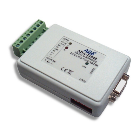
ADA-I1040 User manual ADA-I1040 RS-232 to RS-485 / RS-422 Converter io_ada-i1040_v1.14_en Copyright © 2007-2017 CEL-MAR sp.j. -
Page 2: Table Of Contents
ADA-I1040 Contents 1. GENERAL INFORMATION..................................3 1.1. WARRANTED INFORMATION............................... 3 1.2. GENERAL CONDITIONS FOR SAFE USE............................ 3 1.3. CE LABEL....................................... 3 1.4. ENVIRONMENTAL PROTECTION..............................3 1.5. SERVICE AND MAINTENANCE..............................3 1.6. PACK CONTENTS..................................3 2. PRODUCT INFORMATION..................................3 2.1. PROPERTIES....................................3 2.2. -
Page 3: General Information
1.1. WARRANTED INFORMATION The ADA-I1040 converter is covered by a two year warranty from date of sale. In case of being damaged it will be repair or the damaged component will be replace. The warranty does not cover damage caused from improper use, materials consumption or any unauthorized changes. -
Page 4: Description
The ADA-I1040 should be power from stabilized power supply unit with a voltage ranging from 10 - 30 VDC and minimum power 1W. Converter can be powered from two independent sources, one connected to terminal block second to the JACK 1,5/3,5 connector. -
Page 5: Isolation
Fig. 2. Insulation structure 3. INSTALLATION This chapter will show how to connect ADA-I1040 to RS485/RS422, RS232 bus and power supply. In the purpose of minimization of disruptions from environment is being recommended to: apply multipair type shielded cables, which shield can be connected to the earthing on one end of the cable, –... -
Page 6: Connection To Rs485 / Rs422 Bus
Fig. 4. Connection to RS232 computer port 3.2. CONNECTION TO RS485 / RS422 BUS RS485/RS422 interface of ADA-I1040 converter is available on Tx+/A, Tx-/B, Rx+, Rx- screw terminal block. ADA-I1040 can operate on RS485 and RS422 bus. This two networks should have appropriate wiring. -
Page 7: Connection To 4-Wire Rs485(4W) Bus
ADA-I1040 3.2.2. CONNECTION TO 4-WIRE RS485(4W) BUS After connection of devices according to diagram below the converter should set to functioning on RS485 bus. ADA-I1040 RS232 RS485(4W) RS-485 (4W) bus connector Terminal Tx+/A RS232 DB-9F Tx- /B Power Vss+ Vss- Fig. -
Page 8: Extension Of Rs232 Computer Port
9600Bd. The Line Termination resistor should be use if the distance is over 1000m @ 9600Bd or 700m @ 19200Bd transmission. The Line Terminations (terminators) Rt in ADA-I1040 are connected to RS485/RS422 bus by using the SW1 switch. Example connection of Rt are shown on fig 5,6 & 7. -
Page 9: Operating Mode
Setting the SW2 during data transmission can cause lost data. 4.2. DESCRIPTION OF DIP SWITCH SW1 The SW1 Dip switch on ADA-I1040 is used to set: connection of Line Terminations (terminators) to terminals: [Tx+/A] & [Tx-/B], [Rx+] & [Rx-], –... -
Page 10: Factory Default
5. ACTIVATION After properly connection and setting,according to section above the ADA-I1040 can be power ON. Once activated the green LED PWR on front panel of module should illuminate. If after connection power supply the LED will not lighting, check the correctness of connecting power supply. -
Page 11: Specification
ADA-I1040 8. SPECIFICATION TECHNICAL DATA Transmission Parameters Interface RS-232 RS-485/RS-422 DSUB-9 Female Screw terminal block - max. Ø 2,5mm Connector 15 m 1200 m Max. Line length Max. number of connected device 32 / 2 DB9F/DB9M multicore cable 9x0,34 1-pair or 2-pair twisted cable, UTP Nx2x0,5... - Page 12 Thank you for purchasing CEL-MAR Company product. We hope that this user manual helped connect and start up the ADA-I1040 converter. We also wish to inform you that we are a manufacturer of the widest selections of data communications products in the world such as: data transmission converters with interface RS232, RS485, RS422, USB, Ethernet, Wi-Fi, Current Loop, Fibre-Optic Converters and other.
Need help?
Do you have a question about the ADA-I1040 and is the answer not in the manual?
Questions and answers