Table of Contents
Advertisement
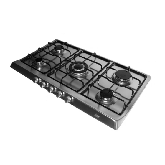
Instructions for the installation
and advice for the maintenance
EX/90 3G AI TR - EX/90 3G AI AL TR
EX/90 4G AI AL - EX/90 5G AI AL TR
EX/90 5G AI AL TR CI - EX/90 5G AI AL PC CI
Instructions Manual
EX/90 3G AI TR - EX/90 3G AI AL TR
EX/90 4G AI AL - EX/90 5G AI AL TR
EX/90 5G AI AL TR CI - EX/90 5G AI AL PC CI
COD. 04032EOTK - 19.12.2007
Advertisement
Table of Contents


Need help?
Do you have a question about the EX/90 3G AI TR and is the answer not in the manual?
Questions and answers