Table of Contents
Advertisement
Installation manual and recommendations for
use and maintenance. Hobs
E/60.2 4G – E/60.2 4G AI – E/60.2 4G AI AL – E/60.2 3G 1P –
E/60.2 3G 1P AI – E/60.2 3G AI AL – E/60.2 4P - ES/60.2 4G –
ES/60.2 4G AL – ES/60.2 4G AI – ES/60.2 4G AI AL –
ES/60.2 3G 1P – ES/60.2 3G 1P AI – ES/60.2 3G AI AL –
Hinweise für den einbau und empfehlungen für den
betrieb und die wartung. Von kochplatten
E/60.2 4G – E/60.2 4G AI – E/60.2 4G AI AL – E/60.2 3G 1P –
E/60.2 3G 1P AI – E/60.2 3G AI AL – E/60.2 4P - ES/60.2 4G –
ES/60.2 4G AL – ES/60.2 4G AI – ES/60.2 4G AI AL –
ES/60.2 3G 1P – ES/60.2 3G 1P AI – ES/60.2 3G AI AL –
Instructions pour l'installation et recommandations
pour l'utilisation et l'entretien plaques de cuisson
E/60.2 4G – E/60.2 4G AI – E/60.2 4G AI AL – E/60.2 3G 1P –
E/60.2 3G 1P AI – E/60.2 3G AI AL – E/60.2 4P - ES/60.2 4G –
ES/60.2 4G AL – ES/60.2 4G AI – ES/60.2 4G AI AL –
ES/60.2 3G 1P – ES/60.2 3G 1P AI – ES/60.2 3G AI AL –
ES/60.2 4G AI AL RÚSTICA
ES/60.2 4G AI AL RÚSTICA
ES/60.2 4G AI AL RÚSTICA
Advertisement
Table of Contents

Subscribe to Our Youtube Channel
Related Manuals for Teka E/60.2 4G AI AL


Summary of Contents for Teka E/60.2 4G AI AL
- Page 1 Installation manual and recommendations for use and maintenance. Hobs E/60.2 4G – E/60.2 4G AI – E/60.2 4G AI AL – E/60.2 3G 1P – E/60.2 3G 1P AI – E/60.2 3G AI AL – E/60.2 4P - ES/60.2 4G –...
- Page 2 TEKA Technical Ser vice personnel. Keep this instruction manual in a safe place...
-
Page 3: Table Of Contents
Contents Introduction Page 4 Description of the hobs Installation Positioning of the hobs Positioning of the oven Anchoring of the hob Gas connection Electrical connection Gas transformation Technical Information Dimensions and power Technical Data Rating Plates Use and maintenance Special requirements before first use Lighting of burners Safety system components Suggestions for the proper use of burners 17... -
Page 4: Introduction
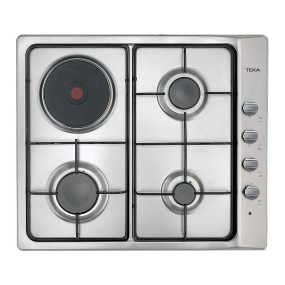
Introduction Description of the Appliance E/60.2 4G, E/60.2 4G AI y E/60.2 4G AI AL E/60.2 3G 1P, E/60.2 3G 1P AI and E/60.2 Models (see drawing 1) 3G 1P AI AL Models (see drawing 2) 1 Small burner of 860 Kcal/h - 1 kW. - Page 5 E/60.2 4P. Model (see drawing 3) ES/60.2 4G, ES/60.2 4G AI, ES/60.2 4G AI AL , ES/60.2 4G AL and ES/60.2 4G AI AL 1 Electric hotplate of 1.000 W., Ø 145 mm. RÚSTICA Models (see drawing 4) 2 Electric hotplate of 1.500 W., Ø 180 mm. 3 Electric hotplate of 1.500 W., Ø...
- Page 6 ES/60.2 3G 1P, ES/60.2 3G 1P AI and ES/60.2 3G 1P AI AL Models (see drawing 5) 1 Small burner of 860 Kcal/h - 1 kW. 2 I n t e rmediate burner of 1.500 Kcal/h - 1,75 kW. 3 Electric heating element of 1.500 W., Ø 145 mm.
-
Page 7: Installation
20 mm If there is not a ventilation slot, the minimum distance from the hob to the kitchen unit must be 130 mm Drawing 8 These hobs only function with TEKA ovens. Ventilation slot Worktop In order to install these hobs in kitchen... -
Page 8: Positioning Of The Oven
Gas connection Positioning of the oven The gas connection of the hob must be made See the applicable manual. in accordance with the applicable installation standards or regulations. Anchoring of the hob The room must be provided with adequate Once the hob position has been dimensioned, ventilation, in accordance with the applicable the seal must be affixed (J) to the hob. -
Page 9: Electrical Connection
TEKA technicians as special tools are required. To make the transformation replace the gas nozzles and regulate the minimum settings of P revent any contact of the power supply cable the taps. - Page 10 . b u rner settings are not carried out by TEKA’s official Technical Ser vice. • Remove the controls and joints from the control panel to access the gas taps.
-
Page 11: Technical Information
E/60.2 4G. E/60.2 4G. AI E/60.2 3G.1P E/60.2 4G ES/60.2 4G AI ES/60.2 3G. 1P E/60.2 4G. AI AL E/60.2 3G 1P AI E/60.2 4P ES/60.2 4G AL ES/60.2 4G AI AL ES/60.2 3G. 1P AI E/60.2 3G 1P AI AL RÚSTIC... -
Page 12: Technical Data
Technical Data COMMON CHARACTERISTICS TO THE ELEC- c) “This appliance must not be connected to a device for the evacuation of combustion pro- TRIC HOTPLATES AND AUTOMATIC LIGHTING ducts. Its installation and connection will be MODEL c a rried out according the installation rules in for- ce. - Page 13 COMMON CHARACTERISTICS TO EVERY MODEL N.B.: All the hob models r e f e rred to in this manual have hot zones during or after their use and can cause burns. Care must be taken when handling these hobs b e f o re installation as there may be ro u g h zones or corners which may be dangerous.
-
Page 14: Rating Plates
50/60 HZ. 1.500W 0 0 9 9 0 0 9 9 TYP. A12312000 TYP. A1D312000 T E K A INDUSTRIAL, S.A. SANTANDER - ESPAÑA E/60.2 4G AI AL Mod. Clase E/60.2 4G AI ∑ Qn Nº 7.50 (P.C.S.) G-110 Vr G-20 Vr 1.70... - Page 15 T E K A INDUSTRIAL, S.A. T E K A INDUSTRIAL, S.A. SANTANDER - ESPAÑA SANTANDER - ESPAÑA E/60.2 3G.1PAI AL ES/60.2. 4G.AI AL Mod. Clase Mod. Clase E/60.2 3G.1PAI ES/60.2. 4G.AI ∑ Qn ∑ Qn Nº Nº 5.75 7.50 (P.C.S.) (P.C.S.) G-110 Vr...
-
Page 16: Use And Maintenance
Use and Maintenance Special requirements before first use Before connecting the hob to the power supply check that the voltage and frequency are tho- se indicated in the rating plate located on the lower par t of the hob. Remove the protecting plastic af fixed to the hob, if any. -
Page 17: Safety System Components
If you smell gas, turn off the gas supply tap of the hob and ventilate the room. The gas installation and the hob must be checked by a specialised technician. Warning: The burners have hot zones during or after their use which may cause burns. Keep children away. -
Page 18: Cleaning And Conservation Of Burners
• Lit burners must not be left uncovered in This is achieved by soaking in warm soapy water and scrubbing with a scouring cloth or a o rder to avoid the wastage of gas and to stif f brush. p revent the excessive heating of the pan s u p p o r t. -
Page 19: Maintenance Of The Burners
Technical Service. To guarantee the air-tightness of the gas installation and the correct operation of the b u rners, the hob must be serviced by TEKA’s Drawing 15 specialised Technical Service at least once ever y four years. -
Page 20: Of Electric Hotplates
Hotplate Ø 180 – 1500 W. • Use completely flat-bottomed pans. A big contact surface between the hotplate and the Control at Power pan leads to a higher heat transmission. The bases of pans should be thick in order to 135 W. - Page 21 • Steam appliances must not be used to clean the heating plate. TEKA INDUSTRIAL, S.A. does not accept any responsibility for any possible fault contained in this instruction manual due to transcription or printing errors.
-
Page 22: If Something Doesn't Work
Important If something doesn’t work Please, check the following before calling the Tecnical Service: Fault Possible Cause Solution Neither the hotplate nor the operation pilot works The mains cable is not connected Connect the mains cable There is not spark when pressing the control which activates the automatic lighting Check/... - Page 23 Budapest, HUNGARY 1 - 111.58.03/04 1 - 111.58.05 TEKA BV Amsterdam, THE NETHERLANDS 31 23 - 565.73.99 23 - 565.03.96 TEKA POLSKA SPOLKA Z O.O. Warszawa, POLAND 22 - 652.18.94 22 - 654.22.66 TEKA PORTUGUESA LTDA. Ilhavo, PORTUGAL 351 34 - 32.95.00 34 - 32.54.57...
Need help?
Do you have a question about the E/60.2 4G AI AL and is the answer not in the manual?
Questions and answers