
Related Manuals for TSI Instruments Dusttrak II 8530


Summary of Contents for TSI Instruments Dusttrak II 8530
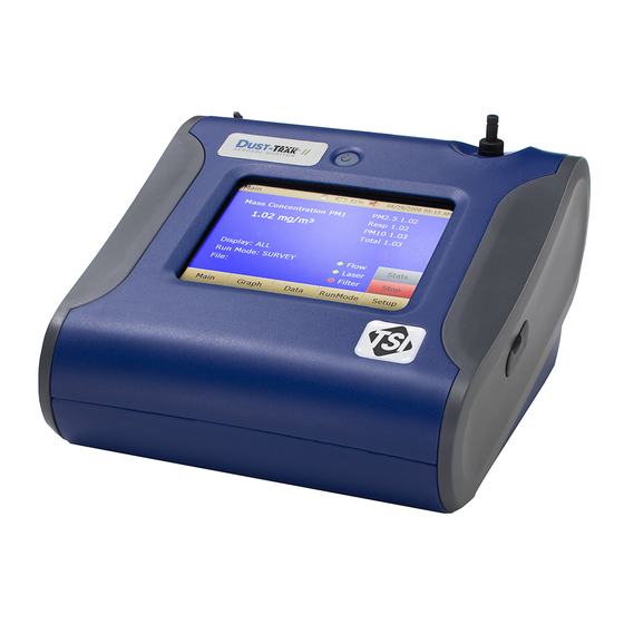
- Page 1 DUSTTRAK ™ AEROSOL MONITOR MODEL 8530/8530EP/8532 OPERATION AND SERVICE MANUAL P/N 6001893, REVISION S JANUARY 2019 DustTrak II 8530 Desktop and 8532 Handheld DustTrak II 8530EP Monitor...
- Page 3 Copyright © TSI Incorporated / 2008–2019 / All rights reserved. Address TSI Incorporated / 500 Cardigan Road / Shoreview, MN 55126 / USA Fax No. (651) 490-3824 Limitation of Warranty and Liability (effective April 2014) (For country-specific terms and conditions outside of the USA, please visit www.tsi.com.) Seller warrants the goods, excluding software sold hereunder, under normal use and service as described in the operator's manual, shall be free from defects in workmanship and material for twenty-four (24) months, or if less, the length of time specified in the...
- Page 4 TO THE EXTENT PERMITTED BY LAW, THE EXCLUSIVE REMEDY OF THE USER OR BUYER, AND THE LIMIT OF SELLER'S LIABILITY FOR ANY AND ALL LOSSES, INJURIES, OR DAMAGES CONCERNING THE GOODS (INCLUDING CLAIMS BASED ON CONTRACT, NEGLIGENCE, TORT, STRICT LIABILITY OR OTHERWISE) SHALL BE THE RETURN OF GOODS TO SELLER AND THE REFUND OF THE PURCHASE PRICE, OR, AT THE OPTION OF SELLER, THE REPAIR OR REPLACEMENT OF THE GOODS.
-
Page 5: Table Of Contents
CONTENTS SAFETY INFORMATION ................V Laser Safety ....................v Labels ......................vi Description of Caution/Warning Symbols ........... vii Caution ....................vii Warning ....................vii Caution and Warning Symbols ..............vii Reusing and Recycling ................vii CHAPTER 1 UNPACKING AND PARTS IDENTIFICATION ....... 1 Unpacking the DustTrak II Aerosol Monitor .......... - Page 6 Log Mode (1–5) ..................38 Locking Feature ..................39 Taking Mass Concentration Measurements ..........41 Screen Regions ..................42 Stats ....................... 43 Graphing ....................43 Viewing Data ....................45 Title Bar ..................... 46 CHAPTER 4 MAINTENANCE ..............47 Maintenance Schedule ................47 Zeroing Instrument ..................
-
Page 7: Safety Information
Safety Information I M P O R T A N T There are no user serviceable parts inside the instrument. Refer all repair and maintenance to a qualified factory-authorized technician. All maintenance and repair information in this manual is included for use by a qualified factory-authorized technician. -
Page 8: Labels
Labels Advisory labels and identification labels are attached to the instrument. 1. Serial Number Label (bottom) 2. Laser Radiation Label DANGER! (internal) VISIBLE LASER RADIATION WHEN OPEN. AVOID DIRECT EXPOSURE TO BEAM WARNING: NO USER SERVICEABLE PARTS INSIDE. REFER SERVICING TO QUALIFIED PERSONNEL 3. -
Page 9: Description Of Caution/Warning Symbols
Description of Caution/Warning Symbols Appropriate caution/warning statements are used throughout the manual and on the instrument that require you to take cautionary measures when working with the instrument. Caution C a u t i o n Failure to follow the procedures prescribed in this manual might result in irreparable equipment damage. - Page 10 (This page intentionally left blank) viii...
-
Page 11: Chapter 1 Unpacking And Parts Identification
Chapter 1 Unpacking and Parts Identification Carefully unpack the Model 8530/8532 DustTrak™ II Aerosol Monitor from the shipping container. Use the tables and illustrations below to make certain that there are no missing components. Contact TSI immediately if anything is missing or damaged. -
Page 12: Unpacking The Dusttrak Ii Aerosol Monitor
Unpacking the DustTrak II Aerosol Monitor Compare all the components you received with those listed in the table below. If any parts are missing, contact TSI. Item Part Number Description 8530 Desktop II 8532 Handheld II 801670 Desktop II Carrying Case 801669 Handheld II... - Page 13 Item Part Number Description 801680 7800 mAH Lithium Ion Rechargeable Battery (Desktop) Rechargeable 801681 lithium ion battery (Handheld) 1303740 USB cable 801652 Analog/alarm output cable (Desktop models only) 6001893 Operation and Service Manual Calibration Certificate Unpacking and Parts Identification...
- Page 14 Item Part Number Description 801688 Conductive Tubing 801668 Filter removal tool (Spanner Driver) 801673 Spare Internal Filter Elements Desktop Model Only 37-mm filter includes: Filter body Filter body bottom Mesh screen Comes with 37-mm cartridge opening tool 801666 Spare Internal Filters Handheld Model Only...
- Page 15 Item Part Number Description 801684 Power Supply – Desktop 801694 Power Supply – Handheld Stylus When shipped, one stylus will be in the accessory bag, the second stylus attached to instrument. 3012094 Screwdriver, dual ended. (For Handheld Models only) 801674 Impactor Oil 801698 Inlet cap...
- Page 16 Item Part Number Description 801797 External Pump Power Cable (to DustTrak monitor) for 8530EP only 801798 External Pump Flow Tube (to DustTrak monitor) for 8530EP only Exhaust Adapter, DustTrak monitor for 8530EP only Chapter 1...
-
Page 17: Optional Accessories
Optional Accessories The following photos and table list optional accessories. If you ordered optional accessories, make certain they have been received and are in working order. Part Accessories Number Description 801675 External Pump DustTrak II/DRX 801795 External Pump Service Kit for 8530EP only. -
Page 18: Parts Identification For The Dusttrak Ii Desktop Aerosol Monitor Models 8530
Parts Identification for the DustTrak II Desktop Aerosol Monitor Models 8530 Stylus Inlet On/Off Touchscreen Analog/Alarm Power Output USB Host USB Device Ethernet Zero Module Connector Battery Access Filter Access Figure 1-1: Features on Desktop Model 8530 Chapter 1... -
Page 19: Parts Identification For The Dusttrak Ii Desktop Aerosol Monitor Model 8530Ep
Parts Identification for the DustTrak II Desktop Aerosol Monitor Model 8530EP External Pump External Pump Power Connection Flow Tubing Exhaust Adapter External Pump External Pump Module (8530EP only) Pump Pump Suction End Pump Exhaust End User Replaceable HEPA Filters Pump Power Connection Figure 1-2: Features on Desktop Model 8530EP Unpacking and Parts Identification... -
Page 20: Parts Identification For The Dusttrak Ii Handheld Aerosol Monitor Model 8532
Parts Identification for the DustTrak II Handheld Aerosol Monitor Model 8532 Inlet On/Off Touchscreen Stylus Port Cover Power USB Host USB Device Filter Access Battery Access (Screw Lockdown) Figure 1-3: Features on Handheld Model Chapter 1... -
Page 21: Chapter 2 Setting Up
Chapter 2 Setting Up Supplying Power to the DustTrak II Aerosol Monitor The DustTrak II Aerosol Monitor must be powered by either batteries or using the external AC adapter. W A R N I N G The instrument has been design to be used with batteries supplied by TSI. -
Page 22: Installing The Batteries In Model 8532 Handheld
Installing the Batteries in Model 8532 Handheld Remove the battery cover by loosening captured screw on the bottom of the unit. Orient battery with brass connectors facing forward. Insert battery into cavity and slide forward to engage into pins. Replace the battery cover and secure by tightening screw (see Figure 2-2). - Page 23 Connect the pump end of the quick connect to the pump module (see Figure 2-3). Figure 2-3: Connect Pump End of Quick Connect to Pump Module Likewise, plug one end of the power connector to the pump module as shown above. Turn the power connector until it clicks and locks in place.
-
Page 24: Using The Ac Adapter To Run Instrument
W A R N I N G The Pump module design does not allow for installation outdoors without any protection from the elements. Always operate it within an enclosure. The DustTrak external pump module does not require an A/C adapter. It is always powered off the DustTrak monitor. -
Page 25: Inlet Cap
Inlet Cap When using the DustTrak monitor to sample environmental air, the inlet cap should be put over the instrument. This cap will keep large objects from dropping into and plugging the inlet. The cap will also keep direct light from shinning into the chamber and skewing the results. -
Page 26: Dorr-Oliver Cyclone
TrakPro software can preprogram the DustTrak monitor, download data, view and create raw data and statistical reports, create graphs, and combine graphs with data from other TSI instruments that use TrakPro software. The following sections describe how to install the software and set up the computer. -
Page 27: Connecting Analog/Alarm Output
Insert the TrakPro Data Analysis Software CD into the CD-ROM drive. The install screen starts automatically. N o t e If the software does not start automatically after a few minutes, manually run the program listed on the label of the CD using the Run command on the Windows Start Menu. -
Page 28: Wiring The Analog Output
Wiring the Analog Output System specifications: Output voltage: 0 to 5 VDC. With a maximum output of 15 mA. Output Current 4 mA to 20 mA with a maximum load impendence of 250 ohms. Correct polarity must be observed (see pin-outs above). The output cable supplied by TSI (P/N 801652) is labeled with the pin-out wiring diagram. -
Page 29: Chapter 3 Operation
Chapter 3 Operation Getting Started The START UP screen is displayed initially when the instrument is turned on, following the initial TSI logo splash screen. Use a stylus or fingertip, touch the “buttons” on the screen to activate different menus. For Model DustTrak 8530EP only W A R N I N G Always setup and operate the DustTrak monitor with External... - Page 30 Communication errors take place under four different scenarios as follows: When the unit is idle and is not connected to the External Pump Module, a warning displays on the Main screen. Note “No Pump is Connected” is a sticky error. Even after the warning message, if the External Pump Module is connected to the DustTrak, the error will not disappear until the screen is refreshed.
- Page 31 If the pump is not connected while attempting to perform a Zero Cal, an error appears on the Setup screen. If the pump is not connected while attempting to perform a Flow Cal, an error appears on the Setup screen. Operation...
-
Page 32: Setup Menu
Setup Menu Pressing Setup activates the Setup Menu touchscreen buttons along the left edge of the screen. Setup is not accessible when the instrument is sampling. The main screen of the Setup screen displays the following information: Serial Number The instruments serial number. Model Number The instruments model number. -
Page 33: Zero Cal
Zero Cal Run Zero Cal the first time the instrument is used and repeat prior to every use. Zero Cal requires that the zero filter be attached prior to running. Zero Cal must also be performed if the unit is reading negative concentrations. It is not possible for the DustTrak to read negative concentrations. -
Page 34: Flow Cal
Flow Cal Run Flow Cal to change the flow set point. The flow set point is factory set to 3 L/min total flow. 2 L/min of the total flow is measured aerosol flow. 1 L/min of total flow is split off, filtered, and used for sheath flow. There is an internal P flowmeter in the DustTrak II instrument that controls flow rate to ±5% of the factory setpoint. -
Page 35: User Cal
User Cal User Cal allows you to store and use 10 different calibration factors. In addition, there are two factory defaults, one is the “Ambient Cal” and the other is the “Factory Cal”. The “Ambient Cal” is appropriate for outdoor ambient dust or fugitive dust monitoring. - Page 36 Name User can rename calibration to a description name. Photometric Changes the factory calibration of particle signal, based on Arizona Road Dust, to actual aerosol being measured. See below for sets to set this calibration. User Cal [on,off] Selecting On will activate current user calibration and deactivate the previously selected user calibration.
- Page 37 Conduct a preflow calibration on the DustTrak monitor using the same kind of sample media you will sample with. Now, attach the sample media you intend to sample with and start sampling aerosol for the desired time. After the desired run time, stop the sampling. Remove the filter from the DustTrak monitor and follow your laboratory’s criteria for filter post weight.
- Page 38 Photometric Calibration Factor In most situations, the DustTrak monitor with its built-in data logging capability can provide very good information on how the concentration of an aerosol changes for different processes over time. Factory calibration to the respirable fraction of standard ISO 12103-1, A1 test dust is fairly representative of a wide variety of workplace aerosols.
- Page 39 N o t e Greater accuracy will be obtained with longer samples. The time you permit for sampling often depends on the reference instrument and characteristics of the measured aerosol. It may take some time to collect sufficient aerosol onto a filter cassette for accurate gravimetric analysis.
-
Page 40: Alarm
Alarm Alarm allows you to set an alarm level that will be triggered if the instrument’s reading goes above the setpoint. However, the alarm functioning is determined by the logging interval. The alarm will turn ON only if the average concentration over the logging interval exceeds the set point. - Page 41 Alarm1 Setpoint [mg/m The alarm1 setpoint is the mass concentration level upon which the alarm1 is triggered. Alarm will trigger if the mass concentration, taken at the logging interval, rises above the setpoint. N o t e Alarm 2 must be lower than Alarm 1 when both alarms are enabled.
-
Page 42: Analog
STEL Alarm STEL stands for Short Term Exposure Limit. When a STEL alarm is selected, the instrument will inspect the data on a second by second basis, independent from the selected logging interval. If the mass exceeds the STEL limit, then a STEL event triggers and the following actions will be taken. STEL indicator The STEL indicator will show Red on the main screen. -
Page 43: Settings
Analog setup screen sets the parameters that will drive the analog out port. Applies to the 8530 Desktop model only. Analog out [On, Off] Turns analog out port on. Size Fraction Selects the size channel that will drive the analog out. Output Setting [V, mA] Select between 0 to 5 V and 4 to 20 mA. - Page 44 Background Switches between blue and white backgrounds. Touch Cal Calibrates the touch cal screen. USB PORT IP Address: USB IP is the address assigned to the instrument by the NDIS driver. It is shown but cannot be changed. Ethernet Port IP parameters: (Model 8530 Desktop only.) IP method can be set to static or dynamic.
-
Page 45: Run Mode
I P N o t e After changing the instrument to Dynamic or Static, reboot the instrument. In Dynamic Mode, the unit will show the IP to which is assigned (after being rebooted). Language Switches between display languages. After changing the display language, reboot the instrument. -
Page 46: Survey Mode
The RunMode tab brings up sampling mode options. Sampling mode options include Survey Mode, Manual Log, and Log Mode 1-5. Survey Survey Mode runs a real time, continuous active sample, but does not log data. Manual Manual Log sets the instrument to log data for a specified run time. -
Page 47: Manual Mode
Manual Mode Log Interval The log interval can be set from 1 second to 60 minutes. It is the amount of time between logged data points. Test Length Test length can be set from 1 minute to the limit of the data storage. -
Page 48: Log Mode (1-5)
Log Mode (1–5) Log Name Log Name, brings up a virtual keypad to name the Logged Data file. Start Date Start Date, select the date the test will start. Start Time Start Time, select the time the test will start. Log Interval The log interval can be set from 1 second to 60 minutes. -
Page 49: Locking Feature
In Log mode, data will be stored to a file named “LogName_XYZ” where LogName is the user entered log name and XYZ is an incrementing integer. Locking Feature The locking feature allows you to lock the screen at any time. This can be done during mass concentration measurements and while the instrument is idle. - Page 50 The screen is now locked. To unlock, touch UNLOCK and re-enter the model number. For 8530EP models, 8530 should be used. After entering the model number, touch OK. N o t e If you happen to enter the model number incorrectly and touch OK, you will be given another chance to enter it correctly.
-
Page 51: Taking Mass Concentration Measurements
Taking Mass Concentration Measurements Measurements are started and controlled from the main screen. Prior to starting a measurement the instrument should be zeroed from the Setup screen and the run mode should be configured and selected from the RunMode screen. When the instrument is on, but not taking any mass measurements the start button will be green and instruments pump will not be running. -
Page 52: Screen Regions
Connect the External Pump Module to the DustTrak monitor and then try again. TSI recommends powering down the DustTrak monitor before connecting the External Pump Module to the DustTrak monitor. Connect the power cable and the flow tubing between the DustTrak monitor and the External pump module, as applicable. -
Page 53: Stats
Stats The Stats button shows the statistics of the mass measurement. When the Stats button is pressed, the main mass reading will reduce in font size, and the measurement statistics will show on the right side of the screen. Graphing During sampling, pressing the Graph button displays current readings in graphical form. - Page 54 Time Display Pressing the Time x-axis label on the graph screen switches between Time (s), Time (abs), and Time (rel). Time (s): Elapsed time from first logged point (log interval) to the last logged point (test length). Time (rel): Relative time from zero to last logged point (test length –...
-
Page 55: Viewing Data
Viewing Data The Data button opens a list of data files for viewing. Select File Press the arrows on the right side of the screen to scroll up or down to the data file to be viewed. Data Statistics Statistics on the selected file File Name Sample Average Sample TWA... -
Page 56: Title Bar
Title Bar The Title Bar shows common instrument information. Date , Time Battery Status Current Screen Instrument Lock Current Screen Title of the current screen that is being displayed. Instrument Lock Icon shows if the instrument touchscreen is in an unlocked or locked condition. -
Page 57: Chapter 4 Maintenance
Chapter 4 Maintenance The DustTrak II aerosol monitor can be maintained in the field using the instructions below. Additionally, TSI recommends that you return your DustTrak II monitor to the factory for annual calibration. For a reasonable fee, we will quickly clean and calibrate the unit and return it to you in “as new” working condition, along with a Certificate of Calibration. -
Page 58: Zeroing Instrument
The DustTrak monitor keeps track of the accumulated amount of aerosol drawn through it since its last cleaning. When the internal filter replacement is due, the filter error indicator will turn from green to red. TSI recommends you perform a zero check prior to each use for the DustTrak monitor and certainly before running any extended tests, and after the instrument experiences a significant environmental change. -
Page 59: Cleaning And Oiling Impactors
Clean the inlet port. Use a cotton swab to clean the outside of the inlet port. You may dampen the swabs with water or a light solvent (e.g., isopropanol). Clean the inside of the sample tube by using a small brush, along with a light solvent. -
Page 60: Replacing The Internal Filters
Replacing the Internal Filters Replace the internal filters based on the schedule in Table 4–1 or when the filter indicator on the main screen changes to red. Turn the instrument off. Remove old filters from the instrument. Handheld Model Use the enclosed filter removal tool (PN 801668) tool to unscrew the two filter caps located on the bottom of the instrument. - Page 61 Pull out single cylindrical filter from filter well. If filter well is visibly dirty, blow out with compressed air. Figure 4-6: Pull out Single Cylindrical Filter from Filter Well (Desktop Model) Put new filer (P/N 801673) back into filter well and screw filter cap back into place.
- Page 62 Remove 37-mm filter cassette by pulling downward and outward. Figure 4-8: Remove 37-mm Filter Cassette Open filter cassette using enclosed tool PN 7001303. Figure 4-9: Open Filter using Enclosed Tool Remove screen mesh from filter cassette and blow out using compressed air.
- Page 63 N o t e s Replacement filters (HEPA and 37-mm Filter Cassette with mesh filter) were shipped with the new instrument. Order additional filters from TSI under PN 801673. TSI does not supply any filter media for the filter cassette. Any commercially available 37-mm filter media may be used with the DustTrak II or DRX desktop instruments to collect gravimetric reference samples.
-
Page 64: Replacing The Filters In The External Pump Module
Replacing the Filters in the External Pump Module The external pump module provided with Model 8530EP is designed to run continuously for about a year (8760 hours). There are two HEPA filters that protect the pump from contamination—one on the suction side of the pump and the other on the discharge side of the pump. -
Page 65: Chapter 5 Troubleshooting
Chapter 5 Troubleshooting The table below lists the symptoms, possible causes, and recommended solutions for common problems encountered with the DustTrak II monitor. Symptom Possible Cause Corrective Action Erratic zero Leak Check connections for leaks reading. Replace zero filter Dirty inlet port and/or Clean inlet port. - Page 66 Symptom Possible Cause Corrective Action Run Mode The selected Run Mode Reduce the number of samples Error: The program is programmed by reducing the test length or selected log to save more samples increasing the logging interval mode will then is room in memory exceed the allowed number of...
- Page 67 Symptom Possible Cause Corrective Action Alarm does not Alarm setting incorrect Check the alarm settings in the turn on Settings->Alarm screen correctly Make sure the logging interval and time constant are set as short as possible (30 seconds or lower) Alarm output wired with Alarm wires are polarized.
- Page 68 Symptom Possible Cause Corrective Action Flow Error is External pump module Make sure both the External indicated on (for Model 8530EP only) Pump cable and the flow tubing front screen is not connected to the connector are connected to the DustTrak monitor DustTrak monitor and the External pump module.
- Page 69 Symptom Possible Cause Corrective Action System Error The processor did not Reboot the instrument. If the has Occurred! receive the input it error does not go away, factory expected. This can also service is required happen if the optics chamber is saturated with light, or the External Pump Cable is accidentally...
- Page 70 (This page intentionally left blank) Chapter 5...
-
Page 71: Appendix Aspecifications
Appendix A Specifications Specifications are subject to change without notice. Sensor Type 90° light scattering Range 8530 Desktop 0.001 to 400 mg/m 8532 Handheld 0.001 to 150 mg/m Resolution ±0.1% of reading or 0.001 mg/m , whichever is greater Zero Stability ±0.002 mg/m 24 hours at 10 sec time constant Particle Size Range... - Page 72 Battery 8530: Up to 2 Removable Li-Ion External and Internal charging Life, 1 battery: >6.5 hours (9 hours typical for a new battery) for both internal and external pump Desktop DustTrak monitors Life, 2 battery: >13 hours 8532: 1 Removable Li-Ion External and Internal charging Life: 5 hours typical Analog out...
-
Page 73: Appendix Bzero Module
Appendix B Zero Module The Zero Module (PN 801690) allows for automatic re-zeroing of the DustTrak Instrument during long sampling runs. The Zero Module works only with the 8530 desktop models. Attach the AutoZero module to the main instrument in two steps. Place the Zero module over the instrument’s inlet and press down. - Page 74 The Zero Module can only be used in a program log mode. The Zero module function is controlled through these two program mode options: Auto Zero Interval Interval between re-zeroing the instrument using the Auto-Zero accessory. Select Yes to use the Zero Module. Select No to Use Auto Zero not use the Zero Module.
-
Page 75: Index
Index battery installation, 11 desktop unit, 11 4-pin miniDIN connector, 17 handheld unit, 12 battery label, vi battery status AC adapter, 14 charging, 46 accessories not charging, 46 8530-NA, 1 optional, 7 advisory labels, vi calibration certificate, 3 aerosol monitor calibration date, 22 maintenance, 47 calibration factor... - Page 76 auto zero interval, 38 log interval, 38 error indicator region, 42 log name, 38 error messages, 55 number of tests, 38 Ethernet port IP parameters, 34 start date, 38 external pump kit, 5, 7 start time, 38 external pump module, 9, 19, 20, 21 test length, 38 connecting, 42 time between tests, 38...
- Page 77 safety information, v test length, 37 save all button, 45 test progress region, 42 screwdriver, 5 time between tests, 38 select file, 45 time constant, 36, 37, 38 serial number, 22 title bar, 46 serial number label, vi alarm, 46 service policy, ii battery status, 46 setting up, 11...
- Page 78 (This page intentionally left blank) Index...
- Page 79 TSI Incorporated – Visit our website www.tsi.com for more information. Tel: +1 800 680 1220 India Tel: +91 80 67877200 Tel: +44 149 4 459200 China Tel: +86 10 8219 7688 France Tel: +33 1 41 19 21 99 Singapore Tel: +65 6595 6388 Germany Tel: +49 241 523030 P/N 6001893 Rev.
Need help?
Do you have a question about the Dusttrak II 8530 and is the answer not in the manual?
Questions and answers