
Subscribe to Our Youtube Channel
Related Manuals for TSI Instruments DUSTTRAK 854201-M1


Summary of Contents for TSI Instruments DUSTTRAK 854201-M1
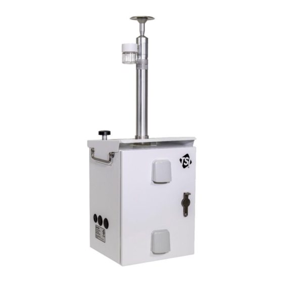
- Page 1 DUSTTRAK ™ ENVIRONMENTAL MONITOR MCERTS VERSIONS ASSEMBLY GUIDE P/N 6010298, REVISION C FEBRUARY 2021...
-
Page 2: Table Of Contents
Contents Contents ............................... 2 Product Overview ............................2 MCERTS PM10 Indicative Certification ....................2 MCERTS PM2.5 Indicative Certification ....................3 MCERTS PM10 and PM2.5 Indicative Certification .................. 3 Installation and Set Up ..........................3 Overview ..............................3 Assembly and Installation of Inlet Column ....................4 Installing the PM10 and PM2.5 Impactors (854020/854021) .............. -
Page 3: Mcerts Pm2.5 Indicative Certification
MCERTS PM2.5 Indicative Certification • 854001-M1 DustTrak™ Environmental Monitor • 854021 PM2.5 Impactor (must be installed) • 854041 Heated Inlet with Omni-directional Inlet and water trap (must be installed) • PCF set at 0.33 (preset at the factory). It is recommended that the instrument is run with a Photometric Correction Factor (PCF) of 0.33. -
Page 4: Assembly And Installation Of Inlet Column
Assembly and Installation of Inlet Column Installing the PM10 and PM2.5 Impactors (854020/854021) 1. Install the water trap bottle onto the side of the Omni Directional Inlet as shown. NO T E For best results, use PTFE Thread Sealant Tape on the water bottle threads. 2. - Page 5 5. Install the Impactor onto the top of the Heated Inlet Sample Conditioner column, by pushing it down. 6. Ensure the O-ring included with the Impactor Kit is installed Impactor into the bottom of the Impactor housing. Housing O-Ring 7. Thread (hand-tighten) the impactor housing with O-ring onto the heated inlet column.
-
Page 6: Installing Heated Inlet (854041) Into Environmental Enclosure
8. Attach the inlet to the top of the impactor housing. Ensure the O-ring included with the inlet kit is installed into the bottom of the inlet. NO T E Be sure to install column retainer ring onto heated inlet column (refer to steps 9 and 10 for visual of retainer ring). - Page 7 3. Insert RH/Temp Sensor through gland and tighten gland nut. Extend probe ~2.75” (7 cm) beyond nut. 4. Attach the sun shield to the top of the RH/Temp Sensor as shown. Sun Shield should not touch sintered cap of RH/Temp Probe. 5.
- Page 8 8. Install O-ring and route cable through the mounting ring. Pull excess cable through to prevent pinching of cable when inlet column is installed. 9. Set inlet column on top of photometer mounting ring, rotate slowly until alignment pin mates with the hole in the bottom of heated inlet column.
-
Page 9: Heated Inlet Operating Instructions
14. If using a Thiamis 1000 Node, route the other side of the cable to the power input on the Thiamis node (green connector). Heated Inlet Operating Instructions 1. When powered and attached to the DustTrak™ monitor, the Heated Inlet will automatically function. 2. -
Page 10: Heated Inlet Specifications
Heated Inlet Specifications Power ............12-24 Volts DC; 13 Watts Dimensions ..........Heated inlet 13 in. x 2 in. dia (33 cm x 5 cm) dia Control module 7 in. x 1.5 in. x 0.75 in. (17.8 cm) x (3.8 cm) x (1.9 cm) Temp Range ........... - Page 11 (This page intentionally left blank) –11–...
- Page 12 _______________ TSI and TSI logo are registered trademarks of TSI Incorporated in the United States and may be protected under other country’s trademark registrations.DustTrak is a trademark of TSI Incorporated. TSI Incorporated – Visit our website www.tsi.com for more information. Tel: +1 800 680 1220 India Tel: +91 80 67877200...
Need help?
Do you have a question about the DUSTTRAK 854201-M1 and is the answer not in the manual?
Questions and answers