
Related Manuals for TSI Instruments dusttrak II 8530


Summary of Contents for TSI Instruments dusttrak II 8530
- Page 1 E x p o s u r e M o n i t o r i n g Model 8530/8531/8532 ™ II Aerosol Monitor Operation and Service Manual P/N 6001893, Revision E March 2010...
- Page 2 Copyright © TSI Incorporated / 2008–2010 / All rights reserved. Limitation of Warranty and Liability (effective July 2000) Seller warrants the goods sold hereunder, under normal use and service as described in the operator's manual, shall be free from defects in workmanship and material for twenty-four (24) months, or the length of time specified in the operator's manual, from the date of shipment to the customer.
-
Page 3: Table Of Contents
CONTENTS SAFETY INFORMATION ..............III Laser Safety ..................iii Labels ....................iv Description of Caution/Warning Symbols ......... iv Caution ..................iv Warning ..................iv Caution and Warning Symbols ............v Reusing and Recycling ..............v CHAPTER 1 UNPACKING AND PARTS IDENTIFICATION ... 1 Unpacking the D ™... - Page 4 Taking Mass Concentration Measurements ........33 Screen Regions ................34 Stats ..................... 35 Graphing ..................35 Viewing Data ................... 37 Title Bar ................... 38 CHAPTER 4 MAINTENANCE ............39 Maintenance Schedule ..............39 Zeroing Instrument ................40 Cleaning the Inlet ................41 Cleaning and Oiling Impactors ............
-
Page 5: Safety Information
Safety Information I M P O R T A N T There are no user serviceable parts inside the instrument. Refer all repair and maintenance to a qualified factory-authorized technician. All maintenance and repair information in this manual is included for use by a qualified factory-authorized technician. -
Page 6: Labels
Labels Advisory labels and identification labels are attached to the instrument. 1. Serial Number Label (bottom) 2. Laser Radiation Label DANGER! (internal) VISIBLE LASER RADIATION WHEN OPEN. AVOID DIRECT EXPOSURE TO BEAM WARNING: NO USER SERVICABLE PARTS INSIDE. REFER SERVICING TO QUALIFIED PERSONNEL 3. -
Page 7: Caution And Warning Symbols
Caution and Warning Symbols The following symbols may accompany cautions and warnings to indicate the nature and consequences of hazards: Warns that the instrument contains a laser and that important information about its safe operation and maintenance is included in the manual. Warns that the instrument is susceptible to electro-static discharge (ESD) and ESD protection should be followed to avoid damage. - Page 8 (page intentionally left blank)
-
Page 9: Chapter 1 Unpacking And Parts Identification
Chapter 1 Unpacking and Parts Identification Carefully unpack the Model 8530/8531/8532 D II Aerosol Monitor from the shipping container. Use the tables and illustrations below to make certain that there are no missing components. Contact TSI immediately if anything is missing or damaged. Note If you purchased a D II Model 8530-NA (no... - Page 10 Part Item Number Description Desktop II 801670 Carrying Case 801669 Handheld II Carrying Case 1090014 Data Analysis Software CD- 800663 Zero Filter 801680 6600 mAH Lithium Ion Rechargeable Battery (Desktop) 801681 Rechargeable lithium ion battery (Handheld) 1303740 USB cable Chapter 1...
- Page 11 Part Item Number Description 801652 Analog/alarm output cable (Desktop models only) Operation and Service Manual Calibration Certificate 801688 Conductive Tubing 801668 Filter removal tool (Spanner Driver) 801673 Spare Internal Filter Elements Desktop Model Only 37-mm filter includes: Filter body top Filter body bottom Mesh screen Comes with...
- Page 12 Part Item Number Description 37-mm cartridge opening tool 801666 Spare Internal Filters Handheld Model Only 801667 Impactor Kit assembled Bottom Impaction Plate Extra Impaction Plate 801691 Dorr-Oliver Cyclone 801692 Power Supply – Desktop Power Supply – 801694 Handheld Stylus When shipped, one stylus will be in the accessory bag, the second...
- Page 13 Part Item Number Description 3012094 Screwdriver, dual ended. (For Handheld Models only) 801674 Impactor Oil 801698 Inlet cap When shipped, one inlet will be in the accessory bag, the second inlet attached to instrument. Unpacking and Parts Identification...
-
Page 14: Monitor Models 8530/8531
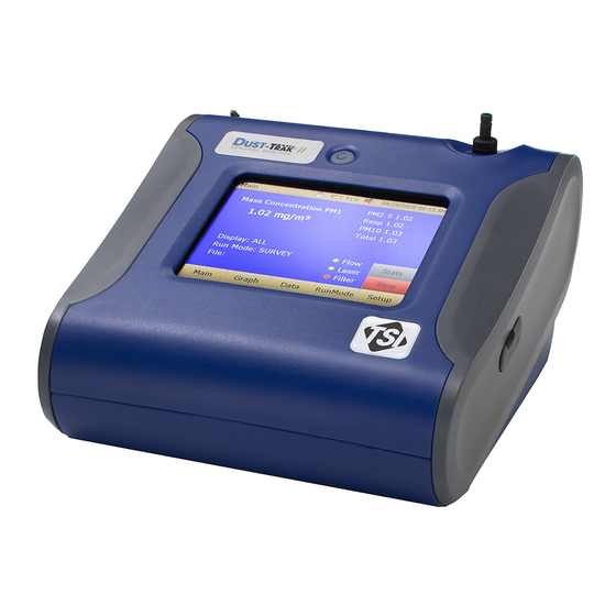
Parts Identification for the D II Desktop ™ Aerosol Monitor Models 8530/8531 Stylus Inlet On/Off Touchscreen Analog/Alarm Output Power USB Host USB Device Ethernet Zero Module Connector Battery Access Filter Access Figure 1-1: Features on Desktop Model Chapter 1... -
Page 15: Ust Trak
Parts Identification for the D II Handheld ™ Aerosol Monitor Model 8532 Inlet On/Off Touchscreen Stylus Port Cover Power USB Host USB Device Filter Access Battery Access (Screw Lockdown) Figure 1-2: Features on Handheld Model Unpacking and Parts Identification... - Page 16 (page intentionally left blank) Chapter 1...
-
Page 17: Chapter 2 Setting Up
Chapter 2 Setting Up Supplying Power to the D II Aerosol Monitor ™ The D II Aerosol Monitor must be powered by either batteries or ™ use of the external AC adapter. W A R N I N G The instrument has been design to be used with batteries supplied by TSI. -
Page 18: Using The Ac Adapter To Run Instrument
Figure 2–2: Batteries into Handheld Unit Using the AC Adapter to Run Instrument The AC adapter allows you to power the D monitor from an AC ™ wall outlet. When using the AC adapter, the batteries (if installed) will be bypassed. -
Page 19: Size-Selective Impactors
Figure 2-3: Putting on Inlet Cap Size-Selective Impactors Size-selective impactors can be attached to the inlet of the D ™ instruments. Size-selective impactors can be used to pre-condition the size range of the particles entering the instrument. PM , PM , PM (Respirable) and PM... -
Page 20: Dorr-Oliver Cyclone
Dorr-Oliver Cyclone A Dorr-Oliver cyclone is shipped with the instrument. The Dorr-Oliver cyclone removes particles over 4.0 µm in size. The Dorr-Oliver cyclone is attached to the instrument by sliding the cyclone clip over the protruding catch. The tube from the Dorr-Oliver cyclone needs to be routed to the inlet of the instrument. -
Page 21: Rak Pro Tm
™ ™ data, view and create raw data and statistical reports, create graphs, and combine graphs with data from other TSI instruments that use T ™ software. The following sections describe how to install the software and set up the computer. -
Page 22: Connecting Analog/Alarm Output
Connecting Analog/Alarm Output The Analog/Alarm Output Cable plugs into the alarm connection on the side of the instrument. This feature is on the desktop models (8530/8531) only. The cable contains a 4-pin, mini-DIN connector. The pin-outs for the connector and the wiring for the cable are shown below. Alarm Positive (+) Analog Output (+) Analog Ground (–) -
Page 23: Wiring The Alarm
Wiring the Alarm System specifications: • Maximum voltage: 15 VDC (DO NOT USE AC POWER) • Maximum current: 1 Amp • Correct polarity must be observed (see pin-outs above) • The alarm switch, located inside the D monitor must be ™... - Page 24 (page intentionally left blank) Chapter 2...
-
Page 25: Chapter 3 Operation
Chapter 3 Operation Getting Started The START UP screen is displayed initially when the instrument is turned on, following the initial TSI logo splash screen. Using a stylus or finger tip, touch the “buttons” on the screen to activate different menus. -
Page 26: Setup Menu
Setup Menu Pressing Setup activates the Setup Menu touchscreen buttons along the left edge of the screen. Setup cannot be accessed when the instrument is sampling. The main screen of the Setup screen displays the following information: Serial Number The instruments serial number. Model Number The instruments model number. -
Page 27: Zero Cal
Zero Cal Zero Cal should be run the first time the instrument is used and should be repeated prior to every use. Zero Cal requires that the zero filter be attached prior to running. Never perform a zero cal without attaching a zero filter. 1. -
Page 28: Flow Cal
Flow Cal Flow Cal is run if the user wants to change the flow set point. The flow set point is factory set to 3 L/min total flow. 2 L/min of the total flow is measured aerosol flow. 1 L/min of total flow is split off, filtered and used for sheath flow. -
Page 29: User Cal
User Cal User Cal allows the user to store and use 10 different calibration factors. The currently active user calibration is highlighted with an asterisk “*”. Four variables can be set for each user calibration. Name User can rename calibration to a description name. - Page 30 Size Corr Changes the factory calibration of the particle distribution, based on Arizona Road Dust, to actual aerosol being measured. See below for sets to set this calibration. User Cal [on,off] Selecting On will activate current user calibration and deactivate the previously selected user calibration.
- Page 31 To make an accurate calibration you must simultaneously measure the aerosol concentration with the D monitor and your reference ™ instrument. 1. Zero the D II monitor. ™ 2. Put the instrument in Manual Log (Manual Logging is reviewed later in this section).
-
Page 32: Alarm
Alarm Alarm allows the user to set an alarm level that will be triggered if the instrument’s reading goes above the setpoint. Alarm1 Setpoint [mg/m The alarm1 setpoint is the mass concentration level upon which the alarm1 is triggered. Alarm will be triggered if the mass concentration, taken at the logging interval, rises above the setpoint. - Page 33 Alarm1 Relay [On, Off] When the relay alarm is turned on, unit will close relay switch when Alarm1 level is surpassed. Relay selection is available on the 8530 and 8531 desktop models only. Alarm1 STEL [On, Off] When the STEL alarm is turned on, STEL data will be collected when Alarm1 level is surpassed.
-
Page 34: Analog
STEL indicator The STEL indicator will show Red on the main screen. Data Data will be taken a 1 minute logging interval for 15 minutes. This data will be stored in a separate file named STEL_XXX, where XXX will be matched to the logged data file. -
Page 35: Settings
Lower Limit [mg/m Mass concentration reading of the selected channel that will correspond to 0 V or 4 mA. Upper Limit [mg/m Mass concentration reading of the selected channel that will correspond to 5 V or 20 mA. Settings Settings screen sets basic unit parameters. Date Time Sets current date, current time and date/time format. - Page 36 USB PORT IP Address: USB IP is the address assigned to the instrument by the NDIS driver. It is shown but cannot be changed. Ethernet Port IP parameters: (Model 8530, 8531 Desktop only.) IP method can be set to static or dynamic. For static IP, IP address, default gateway, and subnet mask can be set.
-
Page 37: Run Mode
Run Mode The RunMode tab brings up sampling mode options. Sampling mode options include Survey Mode, Manual Log, and Log Mode 1-5. Survey Survey Mode runs a real time, continuous active sample, but does not log data. Manual Manual Log sets the instrument to log data for a specified run time. -
Page 38: Survey Mode
Survey Mode Time Constant Time Constant can be set from 1 to 60 seconds. This will control the update rate of the main screen. It is the rolling average of data displayed on the main screen and is not linked to logged data in either Manual or Program Log modes. -
Page 39: Manual Mode
Manual Mode Log Interval The log interval can be set from 1 second to 60 minutes. It is the amount of time between logged data points. Test Length Test length can be set from 1 minute to the limit of the data storage. Time Constant Time Constant can be set from 1 to 60 seconds. -
Page 40: Log Mode (1-5)
Log Mode (1–5) Log Name Log Name, brings up a virtual keypad to name the Logged Data file. Start Date Start Date, select the date the test will start. Start Time Start Time, select the time the test will start. Log Interval The log interval can be set from 1 second to 60 minutes. -
Page 41: Taking Mass Concentration Measurements
Use Start Date Use Start Date, option to use programmed start date or by pass programmed start date. Use Start Time Use Start Time, option to use programmed start time or bypass programmed start time. In Log mode, data will be stored to a file named “LogName_XYZ” where LogName is the user entered log name and XYZ is an incrementing integer. -
Page 42: Screen Regions
Screen Regions Mass Reading Run Mode File Name Test Progress Error Indicators Mass Reading Shows the instruments mass measurements. Run Mode Region Shows the run mode selected from the RunMode screen. File Name Region Displays the file name to which the data is currently being saved. -
Page 43: Stats
Stats The Stats button will show the statistics of the mass measurement. When the Stats button is pressed, the main mass reading will reduce in font size, and the measurement statistics will show on the right side of the screen. Graphing During sampling, pressing the Graph button displays current readings in graphical form. - Page 44 Time Display Pressing the Time x-axis label on the graph screen switches between Time (s), Time (abs), and Time (rel). Time (s): Elapsed time from first logged point (log interval) to the last logged point (test length). Time (rel): Relative time from zero to last logged point (test length –...
-
Page 45: Viewing Data
Viewing Data The Data button opens a list of data files for viewing. Select File Press the arrows on the right side of the screen to scroll up or down to the data file to be viewed. Data Statistics Statistics on the selected file File Name Sample Average Sample TWA... -
Page 46: Title Bar
Title Bar The Title Bar shows common instrument information. Date , Time Battery Status Current Screen Instrument Lock Current Screen Title of the current screen that is being displayed. Instrument Lock Icon shows if the instrument touchscreen is in an unlocked or locked condition. Unlocked: Locked: To lock the touchscreen controls, touch the... -
Page 47: Chapter 4 Maintenance
Chapter 4 Maintenance The D II aerosol monitor can be maintained in the field using the ™ instructions below. Additionally, TSI recommends that you return your II to the factory for annual calibration. For a reasonable fee, ™ we will quickly clean and calibrate the unit and return it to you in “as new” working condition, along with a Certificate of Calibration. -
Page 48: Zeroing Instrument
The D monitor keeps track of the accumulated amount of aerosol ™ drawn through it since its last cleaning. When the internal filter replacement is due, the filter error indicator will turn from green to red. TSI recommends that you perform a zero check prior to each use for the monitor and certainly before running any extended tests, and ™... -
Page 49: Cleaning The Inlet
Cleaning the Inlet The inlet should be cleaned based on the schedule in Table 4–1. 1. Turn the D monitor off. ™ 2. Unscrew the inlet nozzle from the instrument (Figure 4-2). Figure 4-2: Unscrew Inlet Nozzle 3. Clean the inlet port. A cotton swab can be used to clean the outside of the inlet port. -
Page 50: Cleaning And Oiling Impactors
Cleaning and Oiling Impactors The calibration impactor should be cleaned prior to every use, using it to perform a Standard Calibration (size correction) on the instrument, as described in the Operations section. 1. Unscrew Impactor. Check O-ring on the impactor base. 2. - Page 51 Figure 4-5: Pull Filters Out of Two Filter Wells (Handheld Model) Put two (2) new filters into the filter wells and screw filter caps back into place. Note Replacement filters were shipped with the new instrument. Additional filters can be ordered from TSI under PN 801666. Desktop Model Put two (2) new filters into the filter wells and screw filter caps a.
- Page 52 d. Put new filer back into filter well and screw filter cap back into place. Open blue retention clip by pinching ends inward and pushing down. Figure 4-7: Open Blue Retention Clip Remove 37-mm filter cassette by pulling downward and outward. Figure 4-8: Remove 37-mm Filter Cassette Chapter 4...
- Page 53 g. Open filter cassette using enclosed tool PN 7001303. Figure 4-9: Open Filter using Enclosed Tool h. Remove screen mesh from filter cassette and blow out using compressed air. Blow in reverse direction to remove captured particulate. Replace mesh in filter cassette and press halves together. Make sure filter has been fully closed.
-
Page 54: Storage Precautions
Touch the Cum Filter Conc: (live key) to reset the aerosol mass. Touch d. Replace user serviceable filters? Dialog will appear. Press OK. Reset filter concentration? Dialog will appear. Press Yes to reset the cumulative filter concentration to zero. The Setup screen will not show zero for the Cum Filter Concentration and the current date for the Filter Time. -
Page 55: Chapter 5 Troubleshooting
Chapter 5 Troubleshooting The table below lists the symptoms, possible causes, and recommended solutions for common problems encountered with the D ™ monitor. Symptom Possible Cause Corrective Action Erratic zero Leak. Check connections for leaks. reading. Replace zero filter. Dirty inlet port and/or Clean inlet port. - Page 56 Symptom Possible Cause Corrective Action No display. Unit not switched on. Switch unit on. Low or dead batteries. Recharge the batteries or plug in the AC adapter. No touch - Instrument currently busy The instrument will take time screen to open large data files and response.
- Page 57 Symptom Possible Cause Corrective Action Instrument Memory is full. Delete or transfer historic data. does not store new Instrument is in Survey The instrument does not store data mode. data in survey mode. Can to manual or program log mode. Flow Error If sampling from a duct, Attach both the input and the...
- Page 58 (page intentionally left blank) Chapter 5...
-
Page 59: Appendix Aspecifications
Appendix A Specifications Specifications are subject to change without notice. Sensor Type 90° light scattering Range 8530 Desktop 0.001 to 150 mg/m 8531 Desktop HC 0.001 to 400 mg/m 8532 Handheld 0.001 to 150 mg/m Resolution ±0.1% of reading of 0.001 mg/m , whichever is greater Zero Stability... - Page 60 Battery 8530/31: Up to 2 Removable Li-Ion External and Internal charging Life, 1 battery: >6.5 hours (9 hours typical for a new battery) Life, 2 battery: >13 hours 8532: 1 Removable Li-Ion External and Internal charging Life: 6 hours typical Analog out 8530/31: User selectable output 0 to 5 V or 4 to 20 mA...
-
Page 61: Appendix Bzero Module
Appendix B Zero Module The Zero Module (PN 801690) allows for automatic re-zeroing of the Instrument during long sampling runs. The Zero Module ™ works only with the 8530 and 8531 desktop models. The AutoZero module is attached to the main instrument in two steps. The first step is to place the Zero module over the instrument’s inlet and press down. - Page 62 The Zero Module can only be used in a program log mode. The Zero module function is controlled through these two program mode options: Auto Zero Interval Interval between re-zeroing the instrument using the Auto-Zero accessory. Use Auto Zero Select Yes to use the Zero Module. Select No to not use the Zero Module.
-
Page 63: Index
Index battery installation, 9 desktop unit, 9 4-pin miniDIN connector, 14 handheld unit, 10 battery status, 38 AC adapter, 10 accessories calibration certificate, 3 8530-NA, 1 calibration date, 18 advisory labels, iv calibration factor aerosol monitor for specific aerosol, 22 maintenance, 39 calibration impactor specifications, 51... - Page 64 log mode (continued) time constant, 32 file name region, 34 use start date, 33 filter cassette, 44, 45 use start time, 33 troubleshooting, 49 log modes, 29 filter opening tool, 3 log name, 32 filter removal tool, 3 filter time, 18 filter tool, 45 firmware version, 18 maintenance, 39...
- Page 65 save all button, 37 screen regions, 34 test length, 31 screwdriver, 5 test progress region, 34 select file, 37 time between tests, 32 serial number, 18 time constant, 30, 31, 32 serial number label, iv title bar, 38 service policy, 2 alarm, 38 setting up, 9 battery status, 38...
- Page 66 (page intentionally left blank)
- Page 67 Thank you for reading this data sheet. For pricing or for further information, please contact us at our UK Office, using the details below. UK Office Keison Products, P.O. Box 2124, Chelmsford, Essex, CM1 3UP, England. Tel: +44 (0)330 088 0560 Fax: +44 (0)1245 808399 Email: sales@keison.co.uk...
Need help?
Do you have a question about the dusttrak II 8530 and is the answer not in the manual?
Questions and answers