Viessmann VITODENS 100-W Installation And Service Instructions Manual
Type bpja
Hide thumbs
Also See for VITODENS 100-W:
- Installation instructions manual (204 pages) ,
- Installation and service instructions manual (105 pages) ,
- Manual (84 pages)
Table of Contents
Advertisement
VIESMANN
Installation and service
instructions
for contractors
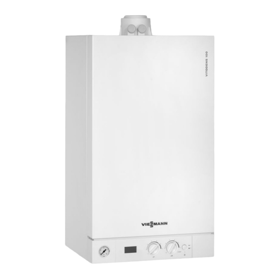
Vitodens 100-W
Type BPJA, 6.5 to 25.0 kW
Wall mounted gas condensing boiler
Natural gas and LPG version
Gas Council no.: 41-819-30, 25 kW; 41-819-31, 29 kW
For applicability, see the last page
VITODENS 100-W
Please keep safe.
5609 913 GB
1/2012
Advertisement
Chapters
Table of Contents

Related Manuals for Viessmann VITODENS 100-W


Summary of Contents for Viessmann VITODENS 100-W
- Page 1 VIESMANN Installation and service instructions for contractors Vitodens 100-W Type BPJA, 6.5 to 25.0 kW Wall mounted gas condensing boiler Natural gas and LPG version Gas Council no.: 41-819-30, 25 kW; 41-819-31, 29 kW For applicability, see the last page VITODENS 100-W Please keep safe.
- Page 2 Safety instructions Safety instructions Please follow these safety instructions closely to prevent accidents and mate- rial losses. Safety instructions explained ■ all current safety regulations as defined by DIN, EN, DVGW, TRGI, Danger TRF, VDE and all locally applicable This symbol warns against the standards, risk of injury.
- Page 3 ■ When using gas as fuel, also close the For replacements, use only orig- main gas shut-off valve and safeguard inal spare parts from Viessmann against unauthorised reopening. or those which are approved by ■ Isolate the system from the power sup- Viessmann.
-
Page 4: Table Of Contents
Index Index Installation instructions Product information................... Preparing for installation................... Installation sequence Fitting the boiler and making connections............10 Opening the control unit casing................15 Electrical connections................... 16 Service instructions Commissioning, inspection, maintenance Steps - commissioning, inspection and maintenance.......... 19 Further details regarding the individual steps............20 Troubleshooting Function sequence and possible faults.............. - Page 5 Index Index (cont.) Keyword index....................68...
-
Page 6: Product Information
2 con- nections for heating flow and return and 2 connections for DHW heating. If the Vitodens 100-W is installed in an S plan or Y plan system, both of the inter- nal connections must be sealed off, as they are not required. -
Page 7: Preparing For Installation
Preparing for installation Preparing for installation Preparing for the boiler installation Dimensions and connections 58 58 A Heating flow 7 22 mm compression E Heating return 7 22 mm compres- fitting sion fitting B Hot water 7 15 mm compression F Condensate drain/safety valve fitting drain: Plastic hose 7 22 mm... - Page 8 Preparing for installation Preparing for installation (cont.) Fitting the wall mounting bracket Ø10 A Vitodens installation template...
- Page 9 Preparing for installation Preparing for installation (cont.) 1. Align the supplied installation tem- plate on the wall. 2. Mark out the rawl plug holes. 3. Drill 7 10 mm holes and insert the supplied rawl plugs. 4. Fit wall mounting bracket with screws supplied.
-
Page 10: Installation Sequence
Installation sequence Fitting the boiler and making connections Removing the front panel and mounting the boiler 1. Undo screws at the bottom of the 3. Hook the boiler into the wall mounting boiler; do not remove completely. bracket. 2. Remove front panel. - Page 11 Installation sequence Fitting the boiler and making connections (cont.) Making connections on the water side C Gas connection G¾ D Cold water G½ E Heating return G¾ For fittings on the heating water side and DHW side, see separate installation instructions. ¨...
- Page 12 Installation sequence Fitting the boiler and making connections (cont.) 2. Carry out a tightness test. Note For the tightness test, use only suita- ble and approved leak detecting agents (EN 14291) and devices. Leak detecting agents with unsuita- ble contents (e.g. nitrites, sulphides) can result in material losses.
- Page 13 Installation sequence Fitting the boiler and making connections (cont.) Connection, safety valve and condensate drain ■ If the condensate line is routed outside the building, use a pipe of at least 7 30 mm and insulate it against frost. Avoid long external pipelines. Please note A frozen condensate pipe can result in faults and boiler dam-...
- Page 14 Installation sequence Fitting the boiler and making connections (cont.) Filling the siphon with water Fill a minimum of 0.3 l of water into the flue outlet. Please note At commissioning, flue gas may be emitted from the condensate drain. Fill the siphon with water before commissioning.
-
Page 15: Opening The Control Unit Casing
Installation sequence Opening the control unit casing Please note Electronic assemblies can be damaged by electrostatic dis- charge. Before beginning work, touch earthed objects, such as heating or water pipes, to discharge static loads. -
Page 16: Electrical Connections
Installation sequence Electrical connections PUMP L N 1 L N 4 3 2 1 A Only for weather-compensated Information on connecting mode: accessories Outside temperature sensor (acces- For this connection, observe the sory) separate installation instructions B OpenTherm device provided with the accessories. C Connecting cable (accessory) D Jumper E Power supply (230 V, 50 Hz). - Page 17 Installation sequence Electrical connections (cont.) Cable entry A Power cable, remote control con- necting cable B LV leads (sensor leads) Power supply Regulations and Directives Install an isolator in the power supply line that simultaneously isolates all non- Danger earthed conductors from the mains with Incorrect electrical installations at least 3 mm contact separation.
- Page 18 Installation sequence Electrical connections (cont.) Danger Connect the appliance and pipe- The absence of component work to the equipotential bonding earthing in the system can lead to of the building in question. serious injury from electrical cur- rent if an electrical fault occurs. Routing connecting cables and closing the control unit Please note Power cables will be damaged if...
-
Page 19: Commissioning, Inspection, Maintenance
Commissioning, inspection, maintenance Steps - commissioning, inspection and maintenance For further information regarding the individual steps, see the page indicated Commissioning steps Inspection steps Maintenance steps Page • • • 1. Filling the heating system..........20 • • • 2. Venting the boiler by flushing........22 •... -
Page 20: Further Details Regarding The Individual Steps
Commissioning, inspection, maintenance Further details regarding the individual steps Filling the heating system Please note ■ Soften fill water harder than Unsuitable fill water increases 300 ppm. the level of deposits and corro- ■ An antifreeze additive suitable sion and may lead to boiler dam- for heating systems can be age. - Page 21 Commissioning, inspection, maintenance Further details regarding the individual steps (cont.) 5. Fill heating system. (System pres- sure 0.8 to 1.2 bar). The system can be filled using a sep- arate filling point fitted at a convenient position on the heating circuit. The connection must be removed when filling is completed.
-
Page 22: Venting The Boiler By Flushing
Commissioning, inspection, maintenance Further details regarding the individual steps (cont.) Venting the boiler by flushing Changing to operation with LPG In the delivered condition, the boiler is Separate installation instruc- set up for operation with natural gas. For tions. operation with LPG, change the gas noz- zle and convert the gas type in the con- Changing from LPG to natural gas - see trol unit. -
Page 23: Matching The Burner Output To The Flue System
Commissioning, inspection, maintenance Further details regarding the individual steps (cont.) Matching the burner output to the flue system To match the burner output to the sys- tem's flue pipe length, a correction factor can be set. 1. Turn ON/OFF switch on. 2. -
Page 24: Adjusting The Circulation Pump To The Heating System
Commissioning, inspection, maintenance Further details regarding the individual steps (cont.) Correction factor Balanced flue operation 7 60/100 mm coaxial 13.5 Observe max. flue lengths. A calculated performance verification is required if the max. flue lengths in the table are excee- ded. -
Page 25: Checking The Static And Supply Pressure
Commissioning, inspection, maintenance Further details regarding the individual steps (cont.) 2. Turn both rotary selectors "tw" and "tr" simultaneously into their cen- tre position. "SERV" appears on the display. 3. Within 2 s, turn rotary selector "tr" to the top right range. "r"... - Page 26 Commissioning, inspection, maintenance Further details regarding the individual steps (cont.) 6. Check the supply (flow) pressure. Set value: ■ Natural gas: 20 mbar ■ LPG: 37 mbar Note Use a suitable measuring device with a resolution of at least 0.1 mbar to check the supply pressure.
-
Page 27: Checking The Co 2 Content
20 mbar for natu- ral gas or 37 mbar for LPG. Notify your gas supply utility or LPG supplier. Checking the CO content Vitodens 100-W is factory-set for natural If the actual CO or O and CO values gas. During commissioning or mainte-... - Page 28 Commissioning, inspection, maintenance Further details regarding the individual steps (cont.) 03. Turn rotary selector "tr" fully clockwise for less than 2 s and then back to the control range on the right. The display shows "SERV", "A" and the boiler water temperature is shown.
- Page 29 Commissioning, inspection, maintenance Further details regarding the individual steps (cont.) 08. ■ If the CO content is within the given range, continue with point ■ If the CO content is outside the given range, check the flue gas/ ventilation air system for tight- ness;...
-
Page 30: Burner Removal
Commissioning, inspection, maintenance Further details regarding the individual steps (cont.) Burner removal F 4x 1. Switch off the power. 5. Undo gas supply pipe fitting E. 2. Shut off the gas supply. 6. Undo four screws F and remove the burner. -
Page 31: Checking The Burner Gasket And Burner Gauze Assembly
Commissioning, inspection, maintenance Further details regarding the individual steps (cont.) Checking the burner gasket and burner gauze assembly Check burner gasket A for damage and Replace the burner gauze assembly if it replace if required. is damaged. 1. Remove electrode B. 4. -
Page 32: Checking And Adjusting Electrodes
Commissioning, inspection, maintenance Further details regarding the individual steps (cont.) 5. Fit thermal insulation ring C. 6. Fit electrode B. Please note Please note Tighten screws far enough Tighten screws far enough to prevent damage to compo- to prevent damage to compo- nents and to ensure the func- nents and to ensure the func- tion is guaranteed. -
Page 33: Cleaning The Heat Exchanger
Commissioning, inspection, maintenance Further details regarding the individual steps (cont.) Cleaning the heat exchanger Please note Scratches on parts that are in contact with flue gas can lead to corrosion. Never use brushes to clean the heat exchanger. Use a vacuum cleaner to remove res- idues from heat exchanger A inside the combustion chamber. -
Page 34: Burner Installation
Commissioning, inspection, maintenance Further details regarding the individual steps (cont.) 7. Check that condensate can drain freely and that the connections are tight. Burner installation A 4x... -
Page 35: Checking The Diaphragm Expansion Vessel And System Pressure
Commissioning, inspection, maintenance Further details regarding the individual steps (cont.) 1. Fit the burner and tighten four screws 6. Check the gas connections for tight- A across. ness. Danger Please note Escaping gas leads to a risk of Tighten screws far enough explosion. -
Page 36: Fitting The Front Panel
Commissioning, inspection, maintenance Further details regarding the individual steps (cont.) Checking gas equipment for tightness at operating pressure Danger Please note Escaping gas leads to a risk of The use of leak detection spray explosion. can result in incorrect functions. Check gas equipment for tight- Leak detection spray must not ness. -
Page 37: Instructing The System User
Commissioning, inspection, maintenance Further details regarding the individual steps (cont.) Instructing the system user The system installer must hand the oper- ating instructions to the system user and instruct the user in the operation of the system. -
Page 38: Troubleshooting
Troubleshooting Function sequence and possible faults Display Action Control unit issues Increase set value a heat demand and ensure heat is drawn off Fan starts After approx. 1 min Check the fan, fan fault F9 connecting cables, power at the fan and fan control Ignition Fault F4... -
Page 39: Fault Messages On The Display
Troubleshooting Function sequence and possible faults (cont.) Burner in opera- Stops below the set Check the flue sys- tion boiler water tem- tem for tightness perature and (flue gas recircula- restarts immedi- tion), check the ately gas flow pressure Fault messages on the display Faults are indicated by a flashing fault code with fault symbol "U"... - Page 40 Troubleshooting Fault messages on the display (cont.) Displayed System characteris- Cause Measures fault code tics Burner blocked Short circuit, flue Check the sensor (see gas temperature page 47). sensor Burner blocked Lead break, flue Check the sensor (see gas temperature page 47).
- Page 41 Troubleshooting Fault messages on the display (cont.) Displayed System characteris- Cause Measures fault code tics Burner in a fault No flame signal Check the ionisation elec- state detected trode and cables, check the gas pressure, check the gas train, ignition, igni- tion module and conden- sate drain.
- Page 42 Troubleshooting Fault messages on the display (cont.) Displayed System characteris- Cause Measures fault code tics Burner blocked Fault, burner con- Check ignition electrodes trol unit and connecting cables. Check whether a strong interference (EMC) field exists near the appliance. Press "Reset" (see page 42).
-
Page 43: Repairs
Troubleshooting Repairs Removing the front panel 1. Release screws at the bottom of the 2. Remove front panel. boiler; do not remove completely. - Page 44 Troubleshooting Repairs (cont.) Boiler water temperature sensor 1. Pull the leads off boiler water temper- ature sensor A and check the resist- ance.
- Page 45 Troubleshooting Repairs (cont.) 2. Check the sensor resistance and compare it with the curve. 3. In the case of severe deviation, drain boiler on the heating water side and replace the sensor. Danger The boiler water temperature sensor is immersed in the heating water (risk of scald- 10 30 50 70 90 110 ing).
- Page 46 Troubleshooting Repairs (cont.) Checking the outlet temperature sensor 1. Pull the leads from outlet temperature sensor A . 2. Check the sensor resistance and compare it with the curve. 3. Replace the sensor in the case of severe deviation. Note Water can leak when replacing the outlet temperature sensor.
- Page 47 Troubleshooting Repairs (cont.) Check flue gas temperature sensor 1. Pull leads from flue gas temperature sensor A . 2. Check the sensor resistance and compare it with the curve.
- Page 48 Troubleshooting Repairs (cont.) 3. Replace the sensor in the case of severe deviation. 10 30 50 70 90 110 Temperature in °C Replacing flow limiter 1. Drain the boiler from the DHW side. 2. Pivot the control unit downwards. 3. Undo screws A. 4.
- Page 49 Troubleshooting Repairs (cont.) Checking or replacing the plate heat exchanger E Heating water flow G Cold water F Heating water return H DHW 1. Shut off and drain the boiler on the 5. Remove two screws C from the heating water and the DHW side. plate heat exchanger and remove plate heat exchanger D with gas- 2.
- Page 50 Troubleshooting Repairs (cont.) 6. Check the DHW side for scaling and 8. Install in reverse order with new gas- if required clean or replace the plate kets. heat exchanger. Note 7. Check the heating water side for con- During installation, ensure that fixing tamination and if required clean or holes are aligned and gaskets seated replace the plate heat exchanger.
-
Page 51: Gas Type Conversion
Gas type conversion Converting from LPG to natural gas Removing gas restrictor 1. Pull power cable from gas train A. 6. Remove or void gas type sticker on the top of the boiler (next to the type plate). 2. Undo union nut B. 7. - Page 52 Gas type conversion Converting from LPG to natural gas (cont.) Changing the gas type at the control unit 1. Turn ON/OFF switch on. 2. Turn both rotary selectors "tw" and "tr" simultaneously into their cen- tre position. "SERV" appears on the display. 3.
-
Page 53: Designs
Designs Connection and wiring diagram Stepper motor diverter valve Vitotrol 100, type UTA or on-site Ignition/ionisation room temperature controller (switched 230 V input) - Page 54 Designs Connection and wiring diagram (cont.) § Vitotrol 100, type RT or on-site Boiler water temperature sensor room temperature controller Outlet temperature sensor (switched 230 V input) No function Vitotrol 100, type UTDB or on-site Flue gas temperature sensor room temperature controller sÖ...
-
Page 55: Parts Lists
Parts lists Ordering parts The following information is required: Standard parts are available from your ■ Serial no. (see type plate A) local supplier. ■ Assembly (from this parts list) ■ Position number of the individual part within the assembly (from this parts list) -
Page 56: Overview Of The Assemblies
Parts lists Overview of the assemblies A Type plate D Control unit assembly B Sheet metal parts assembly E Miscellaneous assembly C Heat cell assembly F Hydraulic assembly... -
Page 57: Sheet Metal Parts Assembly
Parts lists Sheet metal parts assembly 0001 Front panel 0005 Air box floor 0002 Profiled seal 0006 Diaphragm grommets (set) 0003 Logo 0007 Wall mounting bracket 0004 Strain relief upper part 0007 0002 0003 0002 0001 0005 0003 0006 0004... -
Page 58: Heat Cell Assembly
Parts lists Heat cell assembly 0001 Gasket DN 60 0009 Tee 0002 Boiler flue connection 0010 Gas pipe 0003 Boiler flue connection plug 0011 Gasket 17 x 24 x 2 (set) 0004 Flue gas gasket 0012 Burner 0005 Flue gas temperature sensor 0013 Thermal insulation block 0006 Heat exchanger 0014 Heat exchanger mounting (set) -
Page 59: Burner Assembly
Parts lists Burner assembly 0001 Burner gasket 0008 Burner door flange gasket 0002 Thermal insulation ring 0009 Radial fan 0003 Cylinder burner gauze assembly 0010 Gas valve 0004 Burner gauze assembly gasket 0012 Venturi extension 0005 Burner door 0013 Gasket set 0006 Ionisation electrode gasket 0014 Conversion kit G2.350/G27 0007 Ignition and ionisation electrode... - Page 60 Parts lists Burner assembly (cont.) 0007 0006 0005 0004 0003 0002 0001 0006 0008 0012 0013 0010 0014 0009 0013...
-
Page 61: Hydraulic Assembly
Parts lists Hydraulic assembly 0001 Diaphragm expansion vessel 0010 O-ring gasket set 20.6 x 2.6 0002 Support block, diaphragm expan- 0011 Temperature sensor sion vessel 0012 Round sealing ring 8 x 2 (5 pce) 0003 Gasket A 10 x 15 x 1.5 (set) 0013 Moulded hose heating water flow 0004 Connection line;... - Page 62 Parts lists Hydraulic assembly (cont.) 0002 0001 0005 0010 0007 0010 0007 0006 0007 0003 0017 0004 0003 0011 0019 0009 0010 0007 0020 0007 0010 0013 0017 0007 0009 0012 0007 0018 0007 0007 0018 0014 0007 0015 0014 0008 0014 0015...
-
Page 63: Combi Hydraulic Assembly
Parts lists Combi hydraulic assembly 0001 Air vent valve 0013 Expansion tank 0002 O-ring 34 x 3 (5 pce) 0014 Stepper motor adaptor 0003 Plate heat exchanger 0015 Linear stepper motor 0004 Gasket set, plate heat exchanger 0016 Oval cap seal (5 pce) 0005 Safety valve 0017 Water volume controller 0006 Clip Ø... -
Page 64: Control Unit Assembly
Parts lists Control unit assembly 0001 Cover, wiring chamber 0007 Gas valve connecting cable 0002 Clip hinge 0008 Fan connecting cable 0003 Profiled seal 0009 Cable harness stepper motor 0004 Control unit 0010 Fuse 2.5 A (slow) 250 V 0005 Cable harness X20 0006 Ignition cable with angle plug 5 kΩ... -
Page 65: Miscellaneous Assembly
Parts lists Miscellaneous assembly 0001 Touch-up spray paint, white 0004 Operating instructions 0002 Touch-up paint stick, white 0005 Installation and service instruc- 0003 Special grease tions 0001 0002 0003 0004 0005... -
Page 66: Specification
Specification Specification Rated voltage: 230 V~ Temperature limiter Rated frequency: 50Hz setting: 100 °C (fixed) Rated current: 2.0 A~ Backup fuse (power Safety category: supply): IP rating: IP X4 to EN 60529 Permissible ambient temperature ■ during operation: 0 to +40 °C ■... -
Page 67: Certificates
Certificates Declaration of conformity Declaration of Conformity for the Vitodens 100-W We, Viessmann Werke GmbH & Co KG, D-35107 Allendorf, confirm as sole respon- sible body that the product Vitodens100-W complies with the following standards: EN 297 EN 55 014-2... - Page 68 Keyword index Keyword index Boiler water temperature sensor ..44 Ignition..........32 Burner gasket........31 Ignition electrodes......32 Burner gauze assembly.....31 Ionisation electrode......32 Burner installation......34 Burner removal........30 Outlet temperature sensor....46 Output matching Combustion chamber cleaning..33 ■ Flue pipe length......23 Commissioning........20 Condensate........13 Condensate drain......13, 33 Plate heat exchanger......49 Connection diagram......53 Power supply........17...
- Page 72 These service instructions apply for appliances with the following serial num- bers (see type plate): 7501297 7501298 7501823 7501824 Viessmann Werke GmbH&Co KG Viessmann Limited D-35107 Allendorf Hortonwood 30, Telford Telephone: +49 6452 70-0 Shropshire, TF1 7YP, GB Fax: +49 6452 70-2780 Telephone: +44 1952 675000 www.viessmann.com...
Need help?
Do you have a question about the VITODENS 100-W and is the answer not in the manual?
Questions and answers