Table of Contents
Advertisement
Advertisement
Table of Contents

Related Manuals for Bticino M7000CB


Summary of Contents for Bticino M7000CB
-
Page 3: Table Of Contents
CONTENTS 1. General features Page 1.1 Versions Page 1.2 Description Page 1.3 Applications Page 1.4 Installation Page 1.5 Supply Page 2. Description of the front panel Page 2.1 Selection keys Page 2.2 Measurement selection Page 2.3 LEDs Page 3. Operating mode Page 3.1 Reset mode (red LED of RESET key) Page... -
Page 4: General Features
/ outputs 1.5 Supply • M7000CB and M7000CB/EVO have a double power supply circuit, that means that they can operate with both AC and DC supply or with only one of the two indifferently • In presence of both power supplies, the energy is taken from the AC source... -
Page 5: Description Of The Front Panel
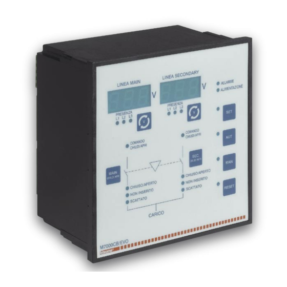
2. Description of the 2.1 Selection keys front panel • The front panel of the electronic control box has two LED displays showing the voltages of the two power sources with their correspondent keys – (A) for Main line and (B) for Secondary line –... -
Page 6: Leds
Electronic Control Box 2.3 LEDs • The front panel has some LEDs which indicate the status of the circuit breakers controlled by the electronic control box. Led L1/L2/L3 Led L1/L2/L3 ALARM LED Presence of Presence of voltage (red) voltage on main on secondary line line (red) (red) -
Page 7: Operating Mode
3. Operating mode • The four keys SET / AUT / MAN / RESET can be used to select the required operating mode, which will be indicated when the corresponding red LED lights up. • If the LED indicating the selected operating mode flashes, it means that the device is communicating through the serial interface and that it could execute remote commands, including the mode change as well. -
Page 8: Off-Load Test Mode (Without Load)
Electronic Control Box 3.4 Off-load test mode • By starting from the automatic mode and by pressing the (F) key for 5 seconds, it will be possible to test the generator for 5 minutes. • The generator is manually started in order to check its operation but since the electronic control box is in automatic mode, the voltage controls will remain active. -
Page 9: Circuit Breakers Control
5. Circuit breakers • The circuit breakers control is carried out through two separate relays, one for closing and one for opening. control • In reset mode, both control relays remain open, except for the emergency condition where the opening can be controlled. •... -
Page 10: Voltage Controls
• The electronic control box can be programmed to perform voltage controls on three- phase, two-phase or single-phase nets (via the P0.03 parameter). The following describes the anomalies monitored by the voltage control. Columns M7000CB and M7000CB/EVO point out the presence of the function within their unit models. Control... -
Page 11: Programming
7. Programming 7.1 Setting the parameters • Press the H and E keys for 5 consecutive seconds to start programming • The flashing LED of the E key indicates that programming is in progress • Main line display indicates the parameter selected via the code (for instance P0.01) •... -
Page 12: Table Of Menus
Electronic Control Box 7.2 Table of menus Menu Description System nominal data General Data Main line voltage control Secondary line voltage control Programmable inputs Programmable outputs Communication port 7.3 P0 menu - Nominal data Setup Description Range Default P0.01 Nominal voltage Ue 100 …... -
Page 13: P1 Menu - General Data
7.4 P1 menu - General data The highlighted param- Setup Description Range Default eters are included only in versionM7000CB/EVO U-G = Utility-to-Generator P1.01 Type of application U-U = Utility-to-Utility OFF - Disabled P1.02 Control of phase sequence 123 - Direct 321 - Opposite FEE - With feedback P1.03... -
Page 14: P2 Menu - Main Line Voltage Control
7.5 P2 menu - Main line voltage control The highlighted param- Setup Description Range Default eters are included only in version M7000CB/EVO P2.01 Minimum voltage threshold - release 70…98 % Ue 85 % Ue P2.02 Minimum voltage threshold - retrieval 75…100 % Ue... -
Page 15: P3 Menu - Secondary Line Voltage Control
Range Default eters are included only in P3.01 Minimum voltage threshold - release 70…98 % Ue 85 % Ue version M7000CB/EVO P3.02 Minimum voltage threshold - retrieval 75…100 % Ue 90 % Ue P3.03 Minimum voltage threshold delay 0.1 …. 900 s 1.0 s... -
Page 16: P5 Menu - Programmable Outputs
Parity RS-485 EVE = Even Odd = Odd P6.01…P6.04 They determine the transmission format and the protocol used on communication port RS-232 P6.05…P6.08 They determine the transmission format and the protocol used on communication port RS-485, available only on M7000CB/EVO... -
Page 17: Diagnostic Messages
8. Diagnostic The following messages can be displayed, at different moments: messages Code Description (Dashes) - The interlocking time is in progress. - - - They are displayed from the side in which the load is being transferred (Start) - Indicates that the Start Generator command has been sent (Cooling) - Indicates that the generator is being left running for the cooling (Test) - When steady, it indicates that an off-load test - namely a power unit test with the voltage controls active - is currently in progress... - Page 18 Description Code Causes RIT RESET MAN AUT are included only in ver- alarm sion M7000CB/EVO This occurs if the P0.06 parameter is OFF and Battery voltage if the battery voltage measured remains lower YES YES too low than the threshold % set with P1.09 for the time set with P1.11...
-
Page 19: Connections
10. Connections Mors. Function Mors. Function Main line circuit breaker opening AL input of Main line circuit breaker DISCONNECTED input of Main line circuit Common main line commands breaker Main line circuit breaker closing AUX input of Secondary line circuit breaker Secondary line circuit breaker opening AL input of Secondary line circuit breaker Common secondary line commands... -
Page 20: Technical Features
Electronic Control Box 11. Technical Auxiliary power supply DC power supply operating limits 9...70VDC (Us=12-24-48VDC) features AC power supply operating limits 187…264VAC (Us=220…240VAC) Frequency 45…65Hz Max. absorbed power 6VA (Us=240VAC) Max. dissipated power 4,8W (Us= 240VAC or Us=48VDC) Max. absorbed current 420mA to 12VDC;... - Page 21 Schema: BT1B Alimentazione centralina e motori a 12-24-48Vdc Wiring diagram: BT1B Electronic Control Box and motors supply in 12-24-48Vdc Programmazione parametri per lo schema in figura: Parameter setting for the wiring diagram in picture: Parametro Impostazione Parameter Setting P0.05 ���������� ����������...
- Page 22 Centralina di commutazione Electronic Control Box Schema: BT2 Alimentazione centralina e motori a 230Vac Wiring diagram: BT2 Electronic Control Box and motors supply in 230Vac Programmazione parametri per lo schema in figura: Parameter setting for the wiring diagram in picture: Parametro Impostazione Parameter...
- Page 23 Schema: BT3 Alimentazione centralina e motori a 230Vac Wiring diagram: BT3 Electronic Control Box and motors supply in 230Vac Programmazione parametri per lo schema in figura: P1.04 = OFF Parameter setting for the wiring diagram in picture: Parametro Impostazione Parameter Setting P1.04 ����������...
- Page 24 Centralina di commutazione Electronic Control Box Schema: BT4 Ingressi di tensione monofase Wiring diagram: BT4 Single-phase voltage inputs Programmazione parametri per lo schema in figura: P1.04 = OFF Parameter setting for the wiring diagram in picture: Parametro Impostazione Parameter Setting P0.03 �������������...
- Page 25 Schema: BT6 Ingressi di tensione trifase Wiring diagram: BT6 Three-phase voltage inputs Programmazione parametri per lo schema in figura: P1.04 = OFF Parameter setting for the wiring diagram in picture: Parametro Impostazione Parameter Setting P0.03 ������������� � � � � �...
- Page 26 Centralina di commutazione Electronic Control Box Schema: BT8 Ingressi di tensione bifase Wiring diagram: BT8 Two-phase voltage inputs Programmazione parametri per lo schema in figura: P1.04 = OFF Parameter setting for the wiring diagram in picture: Parametro Impostazione Parameter Setting P0.03 �������������...
- Page 27 Schema: BT10 MEGATIKER 125/160 senza feedback Wiring diagram: BT10 MEGATIKER 125/160 without feedback Programmazione parametri per lo schema in figura: P1.04 = OFF Parameter setting for the wiring diagram in picture: Parametro Impostazione Parameter Setting P1.03 P1.04 P1.05 Megatiker 125: interblocco meccanico non disponibile Megatiker 125: mechanical interlock not available...
- Page 28 Centralina di commutazione Electronic Control Box Schema: BT11 MEGATIKER 125/160 con feedback Wiring diagram: BT11 MEGATIKER 125/160 with feedback Programmazione parametri per lo schema in figura: P1.04 = OFF Parameter setting for the wiring diagram in picture: Parametro Impostazione Parameter Setting P1.03 P1.05...
- Page 29 Schema: BT12 MEGATIKER 125/160 con EJP e feedback Wiring diagram: BT12 MEGATIKER 125/160 with EJP and feedback Programmazione parametri per lo schema in figura: P1.04 = OFF Parameter setting for the wiring diagram in picture: Parametro Impostazione Parameter Setting P1.03 P1.05 Megatiker 125: interblocco meccanico non disponibile Megatiker 125: mechanical interlock not available...
- Page 30 Centralina di commutazione Electronic Control Box Schema: BT13 MEGATIKER 250/630 senza feedback Wiring diagram: BT13 MEGATIKER 250/630 without feedback Programmazione parametri per lo schema in figura: P1.04 = OFF Parameter setting for the wiring diagram in picture: Parametro Impostazione Parameter Setting P1.03 P1.04...
- Page 31 Schema: BT15 MEGATIKER 250/630 con EJP + feedback + bobina a lancio Wiring diagram: BT15 MEGATIKER 250/630 with EJP + feedback + shunt trip Programmazione parametri per lo schema in figura: P1.04 = OFF Parameter setting for the wiring diagram in picture: Parametro Impostazione Parameter...
- Page 32 Centralina di commutazione Electronic Control Box Schema: BT16 MEGATIKER 250/630 con feedback + bobina a lancio + arresto di emergenza Wiring diagram: BT16 MEGATIKER 250/630 with feedback + shunt trip + emergency stop Programmazione parametri per lo schema in figura: P1.04 = OFF Parameter setting for the wiring diagram in picture: Parametro...
- Page 33 Schema: BT17 MEGATIKER 1600 senza feedback Wiring diagram: BT17 MEGATIKER 1600 without feedback Programmazione parametri per lo schema in figura: Parameter setting for the wiring diagram in picture: Parametro Impostazione Parameter Setting P1.03 P1.04 P1.05...
- Page 34 Centralina di commutazione Electronic Control Box Schema: BT19 MEGATIKER 1600 con feedback + bobina a lancio + arresto di emergenza Wiring diagram: BT19 MEGATIKER 1600 with feedback + shunt trip + emergency stop Programmazione parametri per lo schema in figura: P1.04 = OFF Parameter setting for the wiring diagram in picture: Parametro...
- Page 35 Schema: BT20 MEGATIKER 1600 con EJP + feedback Wiring diagram: BT20 MEGATIKER 1600 with EJP + feedback Programmazione parametri per lo schema in figura: P1.04 = OFF Parameter setting for the wiring diagram in picture: Parametro Impostazione Parameter Setting P1.03 P1.05...
- Page 36 Centralina di commutazione Electronic Control Box Schema: BT21B MEGABREAK senza feedback Wiring diagram: BT21B MEGABREAK without feedback Programmazione parametri per lo schema in figura: P1.04 = OFF Parameter setting for the wiring diagram in picture: Parametro Impostazione Parameter Setting P1.03 P1.04 P1.05...
- Page 37 Schema: BT22B MEGABREAK con feedback e arresto d’emergenza Wiring diagram: BT22B MEGABREAK with feedback and emergency stop Programmazione parametri per lo schema in figura: P1.04 = OFF Parameter setting for the wiring diagram in picture: Parametro Impostazione Parameter Setting P1.03 P1.05...
- Page 38 Centralina di commutazione Electronic Control Box Schema: BT23B MEGABREAK con feedback Wiring diagram: BT23B MEGABREAK with feedback Programmazione parametri per lo schema in figura: P1.04 = OFF Parameter setting for the wiring diagram in picture: Parametro Impostazione Parameter Setting P1.03 P1.05...
- Page 39 Schema: BT24B MEGATIKER 125 Ÿ 1600 con bobina di minima tensione e arresto di emergenza Wiring diagram: BT24B MEGATIKER 125 Ÿ 1600 with UVR and emergency stop Programmazione parametri per lo schema in figura: P1.04 = OFF Parameter setting for the wiring diagram in picture: Parametro Impostazione Parameter...
- Page 40 Centralina di commutazione Electronic Control Box Impostazione Valore Valore Setup Setup dei parametri Value Value Setting of P0.01 P3.01 parameters P0.02 P3.02 P0.03 P3.03 P0.04 P3.04 P0.05 P3.05 P1.01 P3.06 P1.02 P3.07 P1.03 P3.08 P1.04 P3.09 P1.05 P3.10 P1.06 P3.11 P1.07 P3.12 P1.08...
- Page 42 Bticino SpA Via Messina, 38 20154 Milano - Italia Call Center “Servizio Clienti” 199.145.145 (Telefonata a carico del chiamante a tariffazione specifica) www.bticino.it...
Need help?
Do you have a question about the M7000CB and is the answer not in the manual?
Questions and answers