Table of Contents
Advertisement
Quick Links
Advertisement
Table of Contents

Subscribe to Our Youtube Channel
Related Manuals for DX Engineering DXE-40VE-2


Summary of Contents for DX Engineering DXE-40VE-2
- Page 1 40 Meter Vertical Antenna with Top Hat DXE-40VE-2 DXE-40VE-2-INS-Revision 0 © DX Engineering 2013 P.O. Box 1491 ∙ Akron, OH 44309-1491 USA Phone: (800) 777-0703 Tech Support and International: (330) 572-3200 Fax: (330) 572-3279 E-mail: DXEngineering@DXEngineering.com...
-
Page 2: Table Of Contents
Table of Contents Introduction Features Warning Tools Required DXE-40VE-2 Parts List Manual Updates Suggested Parts Not Included Additional Material Needed, Not Supplied Installation Site Selection Radial System Mounting Pipe Assembly Radial Plate to Mounting Pipe Attaching Ground Radial Wires to the Radial Plate... -
Page 3: Introduction
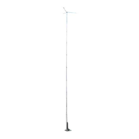
Introduction The DX Engineering 40VE-2 is a fast taper single-band vertical antenna system with a low profile top hat assembly and is slightly less than 25 feet in height. The vertical antenna is specifically designed for low visibility, great for HOA restricted areas, while providing optimum performance on 40 meters. -
Page 4: Tools Required
Every effort is made to supply the latest manual revision with each product. Occasionally a manual will be updated between the time your DX Engineering product is shipped and when you receive it. Please check the DX Engineering web site (www.dxengineering.com) for the latest revision manual. -
Page 5: Suggested Parts Not Included
Made from Laser Cut Stainless Steel with 20 Sets of Stainless Steel Radial Attachment Hardware. The DX Engineering Radial Plate is meant for those of you having a vertical antenna and wanting an easy, neat and effective way to connect those essential radial wires to your antenna system for the highest efficiency and strongest signals. -
Page 6: Radial System
Grass will quickly overgrow the radials and it will be virtually impossible to see them. An article describing this process is available on the DX Engineering website in the Tech Support section. Radials can also be buried just under the surface by using a power edger to make a slit in the soil. -
Page 7: Assembly
Aluminum will quickly corrode due to incompatibility with the materials used to make concrete. Assembly The DXE-40VE-2 is shipped in multiple boxes. Carefully unpack the boxes and identify the parts using the parts list. Note: DXE-P8A Penetrox™ A Anti-Oxidant should be used between all antenna element sections. -
Page 8: Radial Plate To Mounting Pipe
DXE-RADP-3 Radial Plate as shown in Figure 2. Additional hardware kits are available (DXE-RADP-1HWK) that contain 20 sets of Radial Plate Hardware. There are optional DX Engineering Radial Wire Kits available. DXE-RADW-500K/BD contains a 500 foot spool of 14 gauge copper stranded wire with black PVC insulation, 20 Terminal Lugs and 100 Steel or Biodegradable Lawn Staples. -
Page 9: Tilt Base To Mounting Pipe
Radial Wire Pattern Figure 2 - Radial Wire Hardware Installation Tilt Base to Mounting Pipe Install the Tilt Base to the customer supplied 2" OD mounting pipe using the two included DXE-SSVC-2P V-Bolt Saddle Clamps allowing approximately 4-1/2" clearance between the bottom of the tilt base plate, to the top of the DXE-RADP-3 Radial Plate as shown in Figure 3. - Page 10 Using Figure 4, attach the aluminum backing plate to the back of the insulated channel. The base hardware kit contains four 2" hex head bolts, four flat washers, four aluminum spacers, four split washers and four nuts. From the inside of the channel, insert a 2" hex head bolt with a flat washer through each of the middle four holes, through the backing plate.
-
Page 11: Base Section To Tilt Base
Base Section to Tilt Base Place the Lower Base Section into the holes of the mounted Tilt Base and loosely install the Tilt Base mounting hardware shown in Figure 6. Leave the flange nuts and Nyloc nuts slightly loose. Figure - 6 Using a wrench or nut driver, securely tighten the two Nyloc nuts at the bottom of the Tilt Base. -
Page 12: Assembling The Vertical Sections
Test the tilt function to ensure proper clearances. Standing in front of the Tilt Base, lift the antenna base section, slide it to the right, and let it down slightly until the lower outside bolt is resting in the pivot point. Then slowly tilt as shown in Figure 7. Make sure when you are tilting the antenna to lift, slide to the right, and then tilt. - Page 13 Deburring is a finishing method used in manufacturing. Our aluminum tubing is machine cut on both ends and machine slit on one end. Although DX Engineering manufactured aluminum tubing is deburred, you should further assure that there are no ragged edges or protrusions.
- Page 14 Each tubing section is inserted into the next larger tube with an overlap. Assembly is easier if the overlaps in the tubing sections are pre-marked. A dark color felt-tip marker works well. Measure and mark the overlaps as shown in Figure 9 from the end of each tube without the slit using a marker so it will be clearly visible.
- Page 15 Making sure dirt or grass does not adhere to the sections to be joined, insert the marked end of an element tube into the next sized element tube until the mark you made earlier on the element tube is even with the top of the larger element tube section.
-
Page 16: Mating The Vertical Sections To The Tilt Base
Mating the Vertical Sections to the Tilt Base Note: A pair of sawhorses or ladders should be used to support the vertical sections during assembly with the Tilt Base and whenever the vertical is tilted down. Do not allow the tilt-base to support the entire weight vertical when... -
Page 17: Top Hat Parts List
Top Hat Parts List DXE-MPH-1 Multi-purpose Hub (patented) 40VA-2 Top Hat Support Bracket DXE End Insulator (patented) 1/4-20 x 1-1/4” Hex Head Bolt, full thread 1/4-20 x 1” Hex Head Bolt, full thread 1/4-20 Square Nut 1/4-20 Hex Nut 1/4” Split Lock Washer 1/4”... -
Page 18: Top Hat Assembly
Top Hat Assembly Using the Hub, three 1/4-20 x 1-1/4” Hex Bolts, three 1/4-20 Hex Nuts, three 1/4” Split Lock Washers, three 1/4” Flat Washers, and three 1/4” Square Nuts assemble the hardware loosely into the Hub as shown in Figure 12. - Page 19 Insert the Aluminum Spacers into the three End Insulators. as shown in Figure 14. Figure 14 At the ends of the three brackets there are two holes. These holes line up with the two holes in the End Insulators. Install one End Insulator (with Aluminum Spacer) on each of the Top Hat Brackets.
- Page 20 The ends of the three wires you installed will connect to the End Insulator of the next bracket to complete the Top Hat Assembly. Look closely at Figure 17 - The final assembly for details. Use the hardware described in Figure 16 to attach the wires to their respective insulators. Note how the wires are run through the end of the insulators last opening.
- Page 21 Figure 17 - Final Assembly of Top Hat Once the three wires are in place and their hardware is tightened. If you ‘relaxed’ the three brackets when you were routing and connecting the three wires, flatten out the top hat brackets so they are parallel to each other and the Hub.
-
Page 22: Raising The Vertical
Slip the Top Hat Assembly (the Hub) on the top element of the antenna. Install the Black Vinyl Cap on the end of the top antenna element pushing it on as far as it will go. Position the Top Hat Hub approximately 1/4 to 1/2” below the bottom edge of the Black Vinyl Cap. Re-adjust the three bolts (1-2-3 in Figure 18) so the hub is centered around the top element. -
Page 23: Feedpoint Connection
While raising the antenna, keep a constant pulling pressure away from the Tilt Base. This will ensure that the pivot point bolt will not jump out of the pivot slot and cause the tilt mechanism to bind up and bend the bolts. Starting from the top of the antenna, walk it up slowly using an overhead hand-over-hand motion, maintaining a slow and steady pace. - Page 24 The easiest way to make a reliable feedline connection using customer supplied coaxial cable is using the DXE-RADP-3 Radial Plate with the DXE-112-KIT SO-239 Chassis Mount Connector as shown in Figure 20. Use a customer supplied insulated wire soldered on the center pin of the chassis mounted SO-239 (14 gage insulated wire is adequate) to a ring terminal which is connected to the antenna feedpoint hardware.
-
Page 25: Tuning The Vertical
Tuning the Vertical Antenna System The actual impedance of the 40 meter antenna is affected by local conditions, including proximity to structures, other antennas, number of radials, or personal preference for the mounting location. It may be necessary to adjust the top element section slightly longer or shorter when tuning the antenna to best SWR. -
Page 26: Operation On 30 Meters
Operation on 30 meters If desired, the antenna length can be shortened (more overlap of tubing elements) to allow monoband operation on 30 meters. The overall length for 30 meter operation would be 22 feet, 11- 1/4 inches overall length from the top of the antenna to the bottom of the base section element. Plot showing the 30 meter test antenna at 22 feet 11-1/4 inches overall length Optional DXE-VMN-1 Vertical Antenna Matching Network The DXE-VMN-1 Vertical Antenna Matching Network is custom designed for use with... -
Page 27: Guying A Vertical Antenna System
Guying a Vertical Antenna System Guying of the DXE-VE-2 is not required, however, if your area encounters severe wind velocities or icing conditions, simple guying will reduce the possibility of failure. Using the DXE-GUY kits, you can install four guy ropes starting approximately 1/2 the way up the vertical antenna system to ground level. -
Page 28: Optional Accessory Items
DXE-RADP-3 - Radial Plate, Stainless Steel with 20 Sets of SS Radial Attachment Hardware The patented DX Engineering Radial Plate is meant for those of you that have or are building a quarter wave vertical antenna and who want an easy, neat and effective way to connect those essential radial wires and the coax to your vertical antenna for the lowest takeoff angle and strongest signals. - Page 29 2-1/8” OD. The UT-3500 covers sizes from 1-7/8” to 3-1/2” OD. The complete tool kit, model UT-KIT-DBR, includes both sizes of conical tools, a small hand deburrer and a half round file. DX Engineering Tube Deburring Tools are reversible, so they are ideal to debur both ID and OD of aluminum tubing prior to telescoping the sections together.
- Page 30 SUM-900031 - Automatic Wire Stripper/Crimper/Cutter, 24-10 Ga. Our DX Engineering wire stripper uses a spring-loaded design to make quick work of wires ranging from 24 to 10 gauge. Just insert the wire, squeeze the handle, and listen for the click. That’s the sound of another perfect wire stripping job performed in about 2 seconds- a fraction of the time it takes your pocket knife to do the same job.
- Page 31 DXE-3M2155 - 3M Temflex™ 2155 Rubber Splicing Tape. Conformable self-fusing rubber electrical insulating tape. It is designed for low voltage electrical insulating and moisture TRM-06132 sealing applications. For outdoor use, it should be protected from UV deterioration with an overwrap of TRM-06132 - Scotch®...
-
Page 32: Technical Support And Warranty
All products manufactured by DX Engineering are warranted to be free from defects in material and workmanship for a period of one (1) year from date of shipment. DX Engineering’s sole obligation under these warranties shall be to issue credit, repair or replace any item or part thereof which is proved to be other than as warranted;...
Need help?
Do you have a question about the DXE-40VE-2 and is the answer not in the manual?
Questions and answers