MTS Sensors Temposonics R-Series V Brief Instructions
Magnetostrictive linear position sensors
Hide thumbs
Also See for Temposonics R-Series V:
- Operation manual (46 pages) ,
- Operation manual (51 pages)

Related Manuals for MTS Sensors Temposonics R-Series V


Summary of Contents for MTS Sensors Temposonics R-Series V
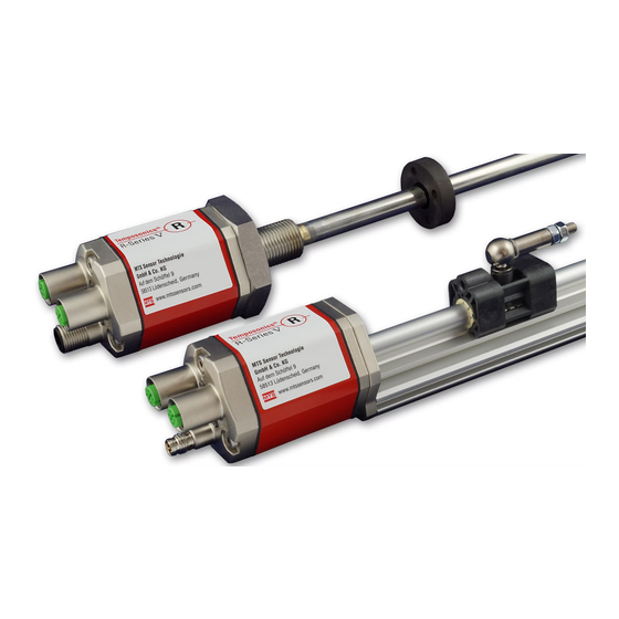
- Page 1 Temposonics ® Magnetostrictive Linear Position Sensors R-Series V Brief Instructions...
-
Page 2: Table Of Contents
R-Series V Temposonics ® Brief Instructions Table of contents 1. Introduction ..................................3 2. Safety instructions ................................4 2.1 Intended use ..................................4 2.2 Foreseeable misuse................................4 2.3 Installation, commissioning and operation ........................5 2.4 Safety instructions for use in explosion-hazardous areas ....................5 2.5 Warranty ..................................5 2.6 Return ....................................5 2.7 Maintenance &... -
Page 3: Introduction
R-Series V Temposonics ® Brief Instructions 1. Introduction 1.1 Purpose and use of this manual Before starting the operation of Temposonics position ® sensors, read this documentation thoroughly and follow the safety information. Keep this manual for future reference! The content of this technical documentation is intended to provide information on mounting, installation and commis- sioning by qualified automation personnel or instructed... -
Page 4: Safety Instructions
Wrong connection Signal output is disturbed of ground / shield The electronics can be damaged Use of a magnet that is not Error in position measurement certifi ed by MTS Sensors Manuals, Software & 3D models available at: www.mtssensors.com... -
Page 5: Installation, Commissioning And Operation
For diagnostic purposes, the sensor can be returned to 5. Ensure the sensor is operating within the defined limits MTS Sensors or a repair facility explicitly authorized by MTS for supply voltage, environmental conditions, etc. Sensors. Any shipment cost will be borne by the sender 6. -
Page 6: Identification
R-Series V Temposonics ® Brief Instructions 3. Identification Nameplate (e.g. R-Series V Profinet) Approvals and certificates Order code RP5SA0200M00D581U402 You will find approvals and certificates in the sensor specific MAC: 00-03-CA-00-58-F6 MAC address S/N: 15030203 Serial number operation manuals. Date of Production 12JAN2018 3.1 Temposonics (profile housing) -
Page 7: Installation & Mounting
R-Series V Temposonics ® Brief Instructions 4. Installation & mounting Typical use of magnets Centered mounting of block magnet For: RH Concentric mounting Concentric mounting • Rotationally symmetrical magnetic field of block magnet of block magnet Ring magnet For: RP & RH •... -
Page 8: Mounting Dimensions
R-Series V Temposonics ® Brief Instructions 4.2 Mounting dimensions RP5 with magnet slider “S” / “N” / “V” / “G” RH5 with ring magnet / U-magnet Sensor electronics housing Sensor electronics housing Reference edge of mounting Reference edge of mounting Start position End position Start position... -
Page 9: Multi-Position Measurement Distances
R-Series V Temposonics ® Brief Instructions 4.3 Multi-position measurement distances Multi-position measurements are possible depending on the The stroke length of the sensor influences the maximum output. It is possible to measure up to 30 positions positions number of magnets. and their velocities. -
Page 10: Electrical Connections & Led Status
R-Series V Temposonics ® Brief Instructions 5. Electrical connections & LED status Placement of installation and cabling have decisive influence 5.1 Profinet on the sensor‘s electromagnetic compatibility (EMC). Hence correct installation of this active electronic system and the EMC of the entire system must be ensured by using suitable Signal metal connectors, shielded cables and grounding. - Page 11 R-Series V Port 1 L/A L/A Port 2 Temposonics ® Brief Instructions Green Information Flashing Sensor identifi cation activated Profi net RT & IRT LED status Port 1 L/A Connection indicator Port 1 L/A L/A Port 2 Port 1 Port 2 Port 1 L/A L/A Port 2 Green...
-
Page 12: Ethernet / Ip
R-Series V Temposonics ® Brief Instructions 5.2 EtherNet / IP™ Ports Signal Port 1 – M12 female Port 1 – M12 female Function Function connector (D-coded) connector (D-coded) Tx (+) Tx (+) Rx (+) Rx (+) Tx (−) Tx (−) Rx (−) Rx (−) View on sensor... - Page 13 Green Information R-Series V Temposonics ® Connection established Flashing No connection Brief Instructions Unrecoverable error Flashing Recoverable error EtherNet/IP™ LED status Port 1 L/A (IN) Connection indicator Port 1 L/A L/A Port 2 Port 1 Port 2 Port 1 L/A L/A Port 2 Green Information...
- Page 14 R-Series V Temposonics ® Brief Instructions Notes...
- Page 15 R-Series V Temposonics ® Brief Instructions Notes...
- Page 16 MTS, Temposonics and Level Plus are registered trademarks of MTS Systems Corporation in the United States; MTS SENSORS and the MTS SENSORS logo are trademarks of MTS Systems Corporation within the United States. These trademarks may be protected in other countries. All other trademarks are the property of their respective owners. Copyright © 2018 MTS Systems Corporation. No license of any intellectual property rights is granted.
Need help?
Do you have a question about the Temposonics R-Series V and is the answer not in the manual?
Questions and answers