
Subscribe to Our Youtube Channel
Related Manuals for Siemens AR10S-MF


Summary of Contents for Siemens AR10S-MF
- Page 1 AR40S-MF AR10S-MF AR10S-MF AR40S-MF Installation and Mounting Version 9.0 Siemens Switzerland Ltd...
- Page 2 Data and design subject to change without notice. / Supply subject to availability. © 2017 Copyright by Siemens Switzerland Ltd We reserve all rights in this document and in the subject thereof. By acceptance of the document the recipient acknowledges these rights and undertakes not to publish the document nor the subject thereof in full or in part, nor to make them available to any third party without our prior express written authorization, nor to use it for any purpose other than for which it was delivered to him.
-
Page 3: Table Of Contents
Content Content 1 Introduction 2 Technical data 3 Safety regulations 3.1 Standards and guidelines 3.2 FCC statements 4 Reader components 5 Mounting and connecting 5.1 Surface mounted reader 5.2 Surface mounted reader with cables fed from outside 5.3 Back box mounted reader 5.4 Back box mounted reader with adapter plate 5.5 Connecting the cables 5.6 Disassembling the reader... -
Page 4: Introduction
1 Introduction 1 Introduction The AR10S-MF and AR40S-MF are executively designed card readers for modern security. The encryption*) is conducted via a protocol which ensures a high level of security, providing that the card reader and system are set to the secure mode. -
Page 5: Technical Data
2 Technical data 2 Technical data AR10S-MF Mifare card reader AR40S-MF Mifare card reader standard standard with keypad and display Protocol OSDP OSDP Interface to controller RS485 RS485 Operating voltage 8.5 – 30.0 VDC 8.5 – 30.0 VDC Power consumption... -
Page 6: Safety Regulations
Siemens Switzerland Ltd hereby declares that this product is in compliance with the essential requirements and other relevant provisions of Radio Equipment Directive 2014/53/EU. The EC Declaration of Conformity is available from your Siemens sales office or: Siemens Switzerland Ltd Gubelstrasse 22... -
Page 7: Reader Components
4 Reader components 4 Reader components Tamper base 1. Hinge 2. Base Screw for removal from wall tamper protection 7 Front 3. Cord gasket 8. Back box plate 4. Knock outs x 4 2017-07-14 Siemens Switzerland Ltd... - Page 8 4 Reader components 1. Screws for back box plate 2. Connector 3. Opening tool – please note that this is a symbolic depiction of the opening tool 2017-07-14 Siemens Switzerland Ltd...
-
Page 9: Mounting And Connecting
"Back box mounted reader " on page 13 – the reader is partly mounted inside a back box in a wall. The two extra screws prevent the reader from rotating. For connecting the cables to the reader, please refer to: "Connecting the cables" on page 14. 2017-07-14 Siemens Switzerland Ltd... -
Page 10: Surface Mounted Reader
3. In case that the removal from wall tamper protection is required, fix the screw into the hole under the tamper base. Ensure to not use excessive force since this can damage the tamper base. 4. Continue to follow the instructions "Connecting the cables" on page 14. 2017-07-14 Siemens Switzerland Ltd... -
Page 11: Surface Mounted Reader With Cables Fed From Outside
4. Hammer the screw driver handle. This will create enough pressure to crack the exact area of the base which will release the knock out. 5. Tilt the knock out with the screwdriver. 6. Pull the knock out away from the base. 2017-07-14 Siemens Switzerland Ltd... - Page 12 9. Feed the cables through the opening and reinsert the cord gasket. Proceed to the instructions for "Connecting the cables" on page 15. It is recommended to seal the gap which the knock out creates. Please note that a reader with a removed knock out is not IP 55. 2017-07-14 Siemens Switzerland Ltd...
-
Page 13: Back Box Mounted Reader
Use only the screws included in the packet for the lower part of the base since those ensure that the reader front will fit perfectly to be securely fitted over the back box. 3. Continue to follow the instructions for "Connecting the cables" on page 15 2017-07-14 Siemens Switzerland Ltd... -
Page 14: Connecting The Cables
But if it is an intermediate reader on the bus, the jumper must be removed (or placed in OFF position). 5. Place the front of the reader with an angle to the hinges at the top of the base. 2017-07-14 Siemens Switzerland Ltd... - Page 15 5 Mounting and connecting 6. Fold the front down until the snap lock confirms a secure attachment. 2017-07-14 Siemens Switzerland Ltd...
-
Page 16: Disassembling The Reader
2. Push gently and lift the front of the base. To remove the connector: 1. Insert the opening tool as indicated on the picture. 2. Push down gently and tilt the connector away from the base. 2017-07-14 Siemens Switzerland Ltd... -
Page 17: Default Settings
Configuration Card Creation Tool (3CT), which enables for required settings to be used for the card readers. For further information, please contact the supplier of this reader. The readers use FreeRTOS. For further information, please visit www.freertos.org. 2017-07-14 Siemens Switzerland Ltd... -
Page 18: Connecting Card Reader To Sipass Integrated
Please note that a new card reader will always get the next free bus address. Should a card reader with bus address 5 be removed and a new card reader be installed, the new card reader will get address 5. 2017-07-14 Siemens Switzerland Ltd... - Page 19 7 Connecting card reader to SiPass integrated 2017-07-14 Siemens Switzerland Ltd...
-
Page 20: Disposal
It is a precondition for reuse and recycling of used electrical and electronic equipment. For more detailed information about disposal of your old appliance, please contact your city office, waste disposal service or the shop where you purchased the product. 2017-07-14 Siemens Switzerland Ltd... - Page 21 Scale 1:1 Units: mm 12.5 42.5...
- Page 22 Issued by Siemens Switzerland Ltd Gubelstrasse 22 © 2017 Copyright by Siemens Switzerland Ltd 6300 Zug Data and design subject to change without notice. Switzerland Supply subject to availability. www.siemens.com/security-solutions Document Nr A-100010-9 2017-07-14 Edition Date...
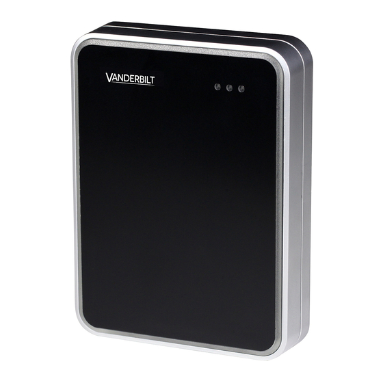
- Page 23 VR40S-MF VR10S-MF VR10S-MF VR40S-MF Installation and Mounting Version 9.0 Vanderbilt International (IRL) Ltd.
- Page 24 Data and design subject to change without notice. / Supply subject to availability. © 2017 Copyright by Vanderbilt International (IRL) Ltd. We reserve all rights in this document and in the subject thereof. By acceptance of the document the recipient acknowledges these rights and undertakes not to publish the document nor the subject thereof in full or in part, nor to make them available to any third party without our prior express written authorization, nor to use it for any purpose other than for which it was delivered to him.
- Page 25 Content Content 1 Introduction 2 Technical data 3 Safety regulations 3.1 Standards and guidelines 3.2 FCC statements 4 Reader components 5 Mounting and connecting 5.1 Surface mounted reader 5.2 Surface mounted reader with cables fed from outside 5.3 Back box mounted reader 5.4 Back box mounted reader with adapter plate 5.5 Connecting the cables 5.6 Disassembling the reader...
-
Page 26: Introduction
1 Introduction 1 Introduction The VR10S-MF and VR40S-MF are executively designed card readers for modern security. The encryption*) is conducted via a protocol which ensures a high level of security, providing that the card reader and system are set to the secure mode. When the secure mode is activated, the communication from neither the reader nor the system they are connected to can be extracted. -
Page 27: Technical Data
2 Technical data 2 Technical data VR10S-MF Mifare card reader VR40S-MF Mifare card reader standard standard with keypad and display Protocol OSDP OSDP Interface to controller RS485 RS485 Operating voltage 8.5 – 30.0 VDC 8.5 – 30.0 VDC Power consumption DC 12V 43mA Peak 168mA DC 12V 60mA Peak 220mA DC 24V 26mA Peak 100mA... -
Page 28: Safety Regulations
3 Safety regulations 3 Safety regulations General Follow all warnings and instructions marked on the device. Keep this document for reference purposes. Please take into account any additional country-specific, local laws, safety standards or regulations concerning installation, operation and disposal of the product. -
Page 29: Reader Components
4 Reader components 4 Reader components 1. Hinge Tamper base 6. Screw for removal from wall tamper protection 2. Base 3. Cord gasket 7 Front 8. Back box plate 4. Knock outs x 4 2017-07-14 Vanderbilt International (IRL) Ltd. - Page 30 4 Reader components 1. Screws for back box plate 2. Connector 3. Opening tool – please note that this is a symbolic depiction of the opening tool 2017-07-14 Vanderbilt International (IRL) Ltd.
-
Page 31: Mounting And Connecting
5 Mounting and connecting 5 Mounting and connecting The reader enables two different mounting alternatives: surface mounted and back box mounted. Those come in two different varieties, depending on how the wires are fed or which kind of back box is used. The reader is delivered with components to support the two mounting alternatives. -
Page 32: Surface Mounted Reader
5 Mounting and connecting 5.1 Surface mounted reader Use drills and screws appropriate for the surface which the reader is to be mounted upon. The surface should be flat to ensure a close fit. To attach the base to the wall: 1. -
Page 33: Surface Mounted Reader With Cables Fed From Outside
5 Mounting and connecting 5.2 Surface mounted reader with cables fed from outside Should the cables be fed from outside: 1. Remove the cord gasket from the base. 2. Identify which of the knock outs the cables should be fed through. 3. - Page 34 5 Mounting and connecting 7. Attach the base to the wall with three screws: one in the middle at the top of the base and two in corners at the bottom of the base. 8. In case that the removal from wall tamper protection is required, fix the screw into the hole under the tamper base.
-
Page 35: Back Box Mounted Reader
5 Mounting and connecting 5.3 Back box mounted reader The reader is mounted on a back box which is attached with two extra screws. 1. Mount the back box plate on to the back box. 2. Attach the extra screws at the lower part of the back box plate in order to prevent rotation. -
Page 36: Connecting The Cables
5 Mounting and connecting 5.4 Connecting the cables Use a pair twisted screened cable (2 pairs + screen), such as Belden 9502. The cables are connected on the respective indicators. Should an extension cable be used, the cables are already attached to the connector. 1. - Page 37 5 Mounting and connecting 6. Fold the front down until the snap lock confirms a secure attachment. 2017-07-14 Vanderbilt International (IRL) Ltd.
-
Page 38: Disassembling The Reader
5 Mounting and connecting 5.5 Disassembling the reader Should the reader need to be taken apart: 1. Carefully insert the opening tool in the slot between the base and the front. 2. Push gently and lift the front of the base. To remove the connector: 1. -
Page 39: Default Settings
6 Default settings 6 Default settings Time-out for configuration card 3 seconds Time-out for display messages 7 seconds Activation time-out 30 seconds Hold-off time for card read 100 milliseconds Reception for card Inactive Character set Windows 1252 Min background illumination Max background illumination Bus address 0 (Up to eight are supported) Off-line indication ... -
Page 40: Connecting Card Reader To Sipass Integrated
7 Connecting card reader to SiPass integrated 7 Connecting card reader to SiPass integrated The connection between a card reader and a Reader Interface Module (RIM) is as follows: RIM (DRI/ERI) VRxx-MF 12 V ⃡ ⃡ Tx/+ ⃡ Rx/- ⃡ 7.1 Setting the card reader address The card readers are delivered in the default mode which is stated in "Default settings"... - Page 41 7 Connecting card reader to SiPass integrated 2017-07-14 Vanderbilt International (IRL) Ltd.
-
Page 42: Disposal
8 Disposal 8 Disposal All electrical and electronic products should be disposed of separately from the municipal waste stream via designated collection facilities appointed by the government or the local authorities. This crossed-out wheeled bin symbol on the product means the product is covered by the European Directive 2002/96/EC. - Page 43 Scale 1:1 Units: mm 12.5 42.5...
- Page 44 Issued by Vanderbilt International (IRL) Ltd. Clonshaugh Business and Technology Park © 2017 Copyright by Vanderbilt International (IRL) Ltd. Clonshaugh Data and design subject to change without notice. Dublin 17 Supply subject to availability. Ireland www.vanderbiltindustries.com Document Nr A-100224-9 2017-07-14 Edition Date...
Need help?
Do you have a question about the AR10S-MF and is the answer not in the manual?
Questions and answers
Hi, in our store we can use either our tags or code. But now i need to change the code and cant find out how to do it. Modell AR40S-MF. Is there a manual for just changing the code?