Table of Contents
Advertisement
Quick Links
®
by Coulomb Technologies
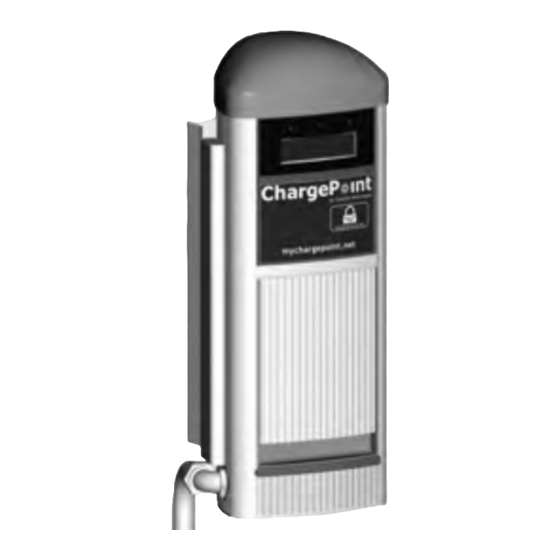
CT1000 Family
ChargePoint
Networked Charging Stations
®
CT1001 Bollard Mount
CT1002 Pole Mount
CT1003 Wall Mount
Installation
Guide
Coulomb Technologies Inc.
1692 Dell Ave.
Campbell, CA 95008-6901 USA
US toll free: +1-877-370-3802
www.coulombtech.com
www.mychargepoint.net
Part Number: 75-001010-01 Revision 1.0
Advertisement
Table of Contents

Subscribe to Our Youtube Channel
Related Manuals for ChargePoint CT1000 series


Summary of Contents for ChargePoint CT1000 series
- Page 1 ® by Coulomb Technologies CT1000 Family ChargePoint Networked Charging Stations ® CT1001 Bollard Mount CT1002 Pole Mount CT1003 Wall Mount Installation Guide Coulomb Technologies Inc. 1692 Dell Ave. Campbell, CA 95008-6901 USA US toll free: +1-877-370-3802 www.coulombtech.com www.mychargepoint.net Part Number: 75-001010-01 Revision 1.0...
- Page 2 ©2009 Coulomb Technologies, Inc. All rights reserved. This material is protected by the copyright laws of the United States and other countries. It may not be modified, reproduced or distributed without the prior, express written consent of Coulomb Technologies, Inc. CHARGEPOINT is a U.S.
-
Page 3: Table Of Contents
Contents Introduction Before installing stations............................1-1 Specifications................................1-2 Wiring diagram (to accommodate future upgrade to a CT2000 or CT2100) ............1-3 Wiring diagram (CT1000 only) ..........................1-4 Installing a Bollard Mount Before you start................................2-1 Overview of steps............................... 2-1 Step 1 - Check box for correct contents ....................2-2 Step 2 - Remove front panel ........................ -
Page 5: Introduction
Introduction ® This document describes how to install any ChargePoint Networked Charging Station in the CT1000 family. It includes step-by-step instructions for installing the body assembly for the following stations: • CT1001 Bollard Mount (see Chapter 2) • CT1002 Pole Mount (see Chapter 3) •... -
Page 6: Specifications
ChargePoint® Networked Charging Stations Specifications Charging connection: NEMA 5-20 AC charging power output: 1.9kW (120V at 16A) AC power input: 120V 16A Recommended service panel breaker: 20A on dedicated circuit Recommended GFCI: Do not provide GFCI at service panel as it can trip before the internal GFCI... -
Page 7: Wiring Diagram (To Accommodate Future Upgrade To A Ct2000 Or Ct2100)
Introduction Wiring diagram (to accommodate future upgrade to a CT2000 or CT2100) The wiring shown below is recommended for installations that expect to upgrade from a CT1000 to a CT2000 or CT2100 charging station. Feeder Lines Electric Meter Breaker Panel Main Breaker 100A Breaker... -
Page 8: Wiring Diagram (Ct1000 Only)
ChargePoint® Networked Charging Stations Wiring diagram (CT1000 only) The wiring shown below is recommended for installations that do not expect to upgrade from a CT1000 to a CT2000 charging station. Feeder Lines Electric Meter Breaker Panel Main Breaker 100A Breaker... -
Page 9: Installing A Bollard Mount
• #2 Phillips screwdriver • #2 Slotted screwdriver Overview of steps ® Installing the CT1001 ChargePoint Networked Charging Station’s body assembly involves a few simple steps: 1. Check box for correct contents (see page 2-2) 2. Remove front panel (see page 2-3) 3. -
Page 10: Step 1 - Check Box For Correct Contents
ChargePoint® Networked Charging Stations Step 1 - Check box for correct contents Bollard Mount Assembly ® ® The CT1001 ChargePoint Networked by Coulomb Technologies CT1000 Family Charging Station’s body assembly ships ChargePoint ® Networked Charging Stations in a box containing:... -
Page 11: Step 2 - Remove Front Panel
Installing a Bollard Mount Step 2 - Remove front panel To remove the front panel: • Use the supplied allen key to loosen the 2 screws that fasten the panel to the body. • Disconnect the ground wire. Slide the front panel upwards to remove. -
Page 12: Step 3 - Remove Body Casing
ChargePoint® Networked Charging Stations Step 3 - Remove body casing To remove the body casing: • Use the supplied allen key to loosen the 4 set screws (2 on each bracket). Loosen the • Slide the body casing upwards to four set remove. -
Page 13: Step 4 - Install J-Bolts And Conduit
Installing a Bollard Mount Step 4 - Install J-Bolts and conduit Install J-Bolts and conduit into concrete as illustrated. Use the supplied base Conduit must extend 12-24” (30-61 cm) above plate template to ensure correct the concrete (check local alignment. codes) IMPORTANT: •... -
Page 14: Step 5 - Mount Base Plate/Pole Assembly
ChargePoint® Networked Charging Stations Step 5 - Mount base plate/pole assembly Pull Neutral (white), Line (black), and Ground (green) wires up through the conduit and the mounting pole. Place the base plate/mounting pole assembly over the wiring conduit and attach the base plate to the J-Bolts using the installer-supplied nuts and washers as shown. -
Page 15: Step 6 - Install Body Casing
Installing a Bollard Mount Step 6 - Install body casing Slide the body casing over the mounting pole and base plate. Ensure the body casing is level. Secure the body casing to the mounting pole by tightening the four set screws using the supplied allen key. -
Page 16: Step 7 - Connect Wires To Wiring Terminals
ChargePoint® Networked Charging Stations Step 7 - Connect wires to wiring terminals Pull Neutral (white), Line (black), and Ground (green) wires into body assembly and connect to wiring terminals. Solid wires are preferred but stranded wires with crimp-on PIN terminators are also OK. -
Page 17: Step 8 - Replace Front Panel
You have now finished installing the body assembly for the CT1001 ® ChargePoint Networked Charging Station’s body assembly. For details on installing the head assembly, see Chapter 5, Installing the head... -
Page 19: Installing A Pole Mount
• #2 Phillips screwdriver • #2 Slotted screwdriver Overview of steps ® Installing the CT1002 ChargePoint Networked Charging Station’s body assembly involves a few simple steps: 1. Check box for correct contents (see page 3-2) 2. Prepare body assembly for mounting (see page 3-3) 3. -
Page 20: Step 1 - Check Box For Correct Contents
ChargePoint® Networked Charging Stations Step 1 - Check box for correct contents Pole Mount Assembly ® ® The CT1002 ChargePoint Networked by Coulomb Technologies CT1000 Family Charging Station’s body assembly ships ChargePoint ® Networked Charging Stations CT1001 Bollard Mount CT1002 Pole Mount... -
Page 21: Step 2 - Prepare Body Assembly For Mounting
Installing a Pole Mount Step 2 - Prepare body assembly for mounting Attach the pole conduit coupler to the body assembly as shown. Attach the body assembly to the pole bracket using the four supplied screws and washers. -
Page 22: Step 3 - Drill Hole In Pole
ChargePoint® Networked Charging Stations Step 3 - Drill hole in pole Drill a 1 ½ “ (38 mm) hole in the pole to accommodate the 1 ¼ ” (32 mm) OD coupling. The maximum height above the surface must be 37” (94 cm) to comply with the Americans with Disabilities Act (ADA). -
Page 23: Step 4 - Strap Body Assembly To Pole
Installing a Pole Mount Step 4 - Strap body assembly to pole Insert the coupler into the hole and hold the body assembly in place using a temporary strap. Strap the body assembly to the pole using ¾ ” (20 mm) by 0.030” (.76 mm) stainless steel banding. -
Page 24: Step 5 - Connect Wires To Wiring Terminals
ChargePoint® Networked Charging Stations Step 5 - Connect wires to wiring terminals Pull Neutral (white), Line (black), and Ground (green) wires into body assembly and connect to wiring terminals. Strip wires, insert in terminal block, and tighten screws to 18.5 inch-lbs (2.1 Nm). -
Page 25: Installing A Wall Mount
• drill and drill bits: one to drill ¼” (6 mm) hole into aluminum and another to drill into masonry Overview of steps ® Installing the CT1003 ChargePoint Networked Charging Station’s body assembly involves a few simple steps: 1. Check box for correct contents (see page 4-2) 2. -
Page 26: Step 1 - Check Box For Correct Contents
ChargePoint® Networked Charging Stations Step 1 - Check box for correct contents Wall Mount assembly ® The CT1003 ChargePoint Networked Charging Station’s body assembly ships in a box containing: • Main body • Wall mount bracket • Screws and washers (6) •... -
Page 27: Step 2 - Attach Bracket To Wall
Installing a Wall Mount Step 2 - Attach bracket to wall Drill 6 holes in the wall, as illustrated. Use the supplied template to ensure correct alignment. Note: If mounting to a hollow wall, mount the holes on the left to a stud using 1/4”... - Page 28 ChargePoint® Networked Charging Stations Step 2 cont’d Using the 6 installer-supplied lag screws and anchors, fasten the wall bracket to the wall.
-
Page 29: Step 3 - Drill Holes In Body Assembly
Installing a Wall Mount Step 3 - Drill holes in body assembly Use a ¼” (6 mm) drill to drill out the 2 mounting holes in the back of the body assembly. These holes are partially pre-drilled. drill mounting holes... -
Page 30: Step 4 - Attach Body Assembly To Wall Bracket
ChargePoint® Networked Charging Stations Step 4 - Attach body assembly to wall bracket Attach the body assembly to the wall bracket using the 6 supplied screws and washers. -
Page 31: Step 5 - Attach Coupler And Connect Conduit
Installing a Wall Mount Step 5 - Attach coupler and connect conduit Attach ¾”(20 mm) installer-supplied coupler to the body assembly, as shown, and connect the conduit. -
Page 32: Step 6 - Connect Wires To Wiring Terminals
ChargePoint® Networked Charging Stations Step 6 - Connect wires to wiring terminals Pull Neutral (white), Line (black), and Ground (green) wires into body assembly and connect to wiring terminals. Strip wires, insert in terminal block, and tighten screws to 18.5 inch-lbs (2.1 Nm). -
Page 33: Installing The Head Assembly
• Torx Driver T15 - Tamper-Resistant Overview of steps ® Installing the ChargePoint Networked Charging Station’s head assembly involves a few simple steps: 1. Check box for correct contents (see page 5-2) 2. Slide head assembly into body (see page 5-3) -
Page 34: Step 1 - Check Box For Correct Contents
ChargePoint® Networked Charging Stations Step 1 - Check box for correct contents Head assembly ® The ChargePoint Networked Charging Station’s head assembly ships in a box containing: • head assembly • Security screws (4) • Rubber plugs (4) • Spare label (keep this label for future reference—it contains... -
Page 35: Step 2 - Slide Head Assembly Into Body
Installing the head assembly Step 2 - Slide head assembly into body Slide the head assembly into body far enough to connect “pigtail” connector. Connect pigtail connector. The head assembly will power-up. Firmly slide head module all the way into body. Open door and check alignment of security screw holes. -
Page 36: Step 3 - Secure Head Assembly
IMPORTANT: It is critical that all 4 plugs are flush with the surface. If they protrude even slightly, the door will not close properly. ® You have now finished installing the ChargePoint Networked Charging Station. - Page 38 Coulomb Technologies Inc. 1692 Dell Ave. Campbell, CA 95008-6901 USA US toll free: +1-877-370-3802 www.coulombtech.com www.mychargepoint.net...
Need help?
Do you have a question about the CT1000 series and is the answer not in the manual?
Questions and answers