
Related Manuals for ChargePoint CPF25


Summary of Contents for ChargePoint CPF25
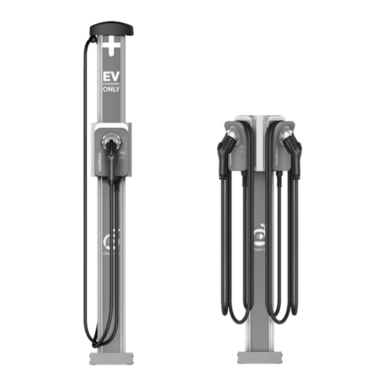
- Page 1 CPF25 Pedestal Mount Charging Stations Installation Guide ChargePoint, Inc. 254 East Hacienda Avenue Campbell, CA 95008 USA US toll free: +1-877-850-4562 www.chargepoint.com...
-
Page 2: Table Of Contents
Step 5: Connect the Charging Cord(s) ..........................4-3 Step 6: Attach the Station Covers ............................4-4 Step 7: Attach the Charging Cord(s) to the CMK ......................4-5 Prepare to Activate on ChargePoint You Will Need ....................................5-1 Overview of Steps ..................................5-1 Step 1: Pinpoint the Station(s) ..............................5-2... -
Page 3: Before You Install
You must be a licensed electrician and complete an online training class http://chargepointuniversity.netexam.com/) to become a ChargePoint Certified Installer, and to get a login for ChargePoint. If you do not complete this training, you will be unable to complete the installation process. DANGER: RISK OF SHOCK Turn off the circuit breaker and do not restore power until installation is complete. -
Page 4: Check Shipping Boxes For Correct Contents
Spare Activation Label (1). A duplicate label is attached to the inside of the main unit. KEEP this spare label because it contains important information that is needed to activate the station on ChargePoint (Section 5). *Not used in pedestal mount installations. These can be discarded. - Page 5 Before You Install Pedestal • Main body • Pedestal Covers (3)* • Pedestal CMK Spacer (attached) • 8-32 X 3/8” Screws (4) *Only two pedestal covers are needed. One can be discarded depending on whether a Cord Management Kit (CMK) is being installed. NOTE: To prepare the installation site for installing a pedestal mount, you will also need the contents of the Pedestal Mount Kit, which ships separately (see...
- Page 6 ChargePoint® Charging Stations Bracket Kit The contents of the bracket kit varies depending on the specific model ordered. Single Station (no Cord Management) • Bracket • 10-32 x 4" screws (4) • Lock Washers (4) Single Station with Cord Management •...
- Page 7 Before You Install Cord Management Kit (CMK) If you ordered the optional cord management kit, it ships in a box containing: • Cord management assembly with pre-installed “EV CHARGING ONLY” sign (1) • Cable clamps (2 extra sets)
-
Page 8: Install The Pedestal
Install the Pedestal Before installing the pedestal, you must prepare the installation site. For detailed instructions, see Appendix B. Step 1: Mount and Level the Pedestal • Pull servicing wiring up through the conduit, leaving approximately 6’ extending out of the conduit. •... -
Page 9: Step 2: Install Pedestal Covers
ChargePoint® Charging Stations Step 2: Install Pedestal Covers • Position the two-piece pedestal covers over the If not using a cord management kit, use the back pedestal cover without the indentation: bottom of the pedestal, as shown. • Insert the two 8-32 x 3/8” screws into each side of the pedestal, as shown. -
Page 10: Install Bracket And Cmk
IMPORTANT ! This section describes how to attach the mounting bracket and its associated components to the pedestal. Follow the steps associated with the particular CPF25 model you are installing: Single Station (no Cord Management) - see page 3-3 Single Station with Cord Management - see page 3-5... -
Page 11: Preparation (Stations With Cord Management)
ChargePoint® Charging Stations Preparation (stations with Cord Management) If your station has a Cord Management Kit, follow these steps to prepare the CMK for mounting: • Position the CMK packaging so its bottom is located near the base of the wall where you are installing the charging station.. -
Page 12: Single Station (No Cord Management)
Install Bracket and CMK 3.1 Single Station (no Cord Management) Remove the ground lug using a 7/16” wrench (save the 1/4”x20 screws to reinstall). Connect the ground wire from the service wiring to the ground lug, then run a 10-gauge ground wire from the ground lug through the wiring opening in front of the pedestal. - Page 13 ChargePoint® Charging Stations 6. Fasten the bracket to the pedestal by inserting the four 10/32 x 4” screws and lock washers through the bracket and into the stand-offs on the pedestal. Tighten using a Phillips screwdriver. Route the service wiring through the wiring hole in the 10/32 x 4”...
-
Page 14: Single Station With Cord Management
Install Bracket and CMK 3.2 Single Station with Cord Management Remove the ground lug by removing its two screws using a 3/8” socket wrench (save the screws to reinstall in step 3 below). Connect the ground wire from the service wiring to the ground lug, then run a 10-gauge ground wire from the ground lug through the wiring opening in front of the pedestal. - Page 15 ChargePoint® Charging Stations 6. Insert the four 1/4”-20 x 4" hex screws and lock washers through the bracket and pedestal. Route the service wiring through the wiring hole in the front of the bracket, as shown. 1/4”-20 x 4" hex screws (4) 1/4”...
-
Page 16: Dual Station (No Cord Management)
Install Bracket and CMK 3.3 Dual Station (no Cord Management) Slide the bottom bracket brace over the pedestal, allowing it to drop to the bottom. Remove the ground lug using a 7/16” wrench (save the 1/4”x20 screws to reinstall). Connect the ground wire from the service wiring to the ground lug, then run two 10-gauge ground wires from the ground lug through the wiring opening in front of the pedestal. - Page 17 ChargePoint® Charging Stations 6. Slide the main bracket over the pedestal, aligning the holes in the main bracket with the corresponding holes in the pedestal. Fasten the main bracket to the pedestal using 10-32 x 4” screws and lock washers at the top and two 10-32 x 4”...
- Page 18 Install Bracket and CMK 9. Slide the bottom brace up, aligning its holes with the main bracket and fastening to the main bracket using two #8 - 32 x 3/8” screws on each side. You have now completed installation of the bracket and are ready to install the stations and charging cords as described in the Section 4.
-
Page 19: Dual Station With Cord Management
ChargePoint® Charging Stations 3.4 Dual Station with Cord Management Slide the bottom bracket brace over the pedestal allowing it to drop to the bottom. Remove the ground lug using a 7/16” wrench (save the two 1/4”x20 screws to reinstall). Connect the ground wire from the service wiring to the... - Page 20 Install Bracket and CMK 9. Slide the main bracket over the pedestal, aligning the holes in the main bracket with the corresponding holes in the top internal brace. 10. Route the service wiring each of the wiring holes located in the left front corner of each main bracket. 11.
- Page 21 ChargePoint® Charging Stations 12. Slide the bottom brace up, aligning its holes with the main bracket and fastening it to the main bracket using two 8-32X3/8” screws on each side. You have now completed installation of the bracket and CMK and are ready to install the stations and charging cords as described in the Section 4.
-
Page 22: Install Station(S) And Charging Cord(S)
Install Station(s) and Charging Cord(s) Step 3: Mount the Station(s) Follow these steps for each station: 1/4” - 20 x 3/8”screw (1) • Insert a 1/4” - 20 x 3/8”screw into the top center hole on the front bracket using a #2 Phillips screwdriver but leave the screw protruding approximately 1/4”... -
Page 23: Step 4: Connect The Service Wiring
ChargePoint® Charging Stations Step 4: Connect the Service Wiring Follow these steps for each station: Trim the service wiring to remove excess length while ensuring that the wiring can easily reach the connectors on the charging station’s terminal block. Strip each wire 1/2”. -
Page 24: Step 5: Connect The Charging Cord(S)
Install Station(s) and Charging Cord(s) Step 5: Connect the Charging Cord(s) Follow these steps for each charging cord: Remove the cable clip connected to the wiring end of the cord, but do not discard it. Note the location of the slot because you will be re-inserting the clip into this same location. -
Page 25: Step 6: Attach The Station Covers
ChargePoint® Charging Stations Step 6: Attach the Station Covers Follow these steps for each station: Attach the wire covers: • Place the wire cover over the exposed wiring on the terminal block. • Using a coin, lock the wire cover in place, as shown. -
Page 26: Step 7: Attach The Charging Cord(S) To The Cmk
LEFT side of the station to minimize interference with the card reader. The physical installation of the CPF25 is now complete and you are ready to prepare the station for activation on ChargePoint, as described in the next section. -
Page 27: Prepare To Activate On Chargepoint
Prepare to Activate on ChargePoint Before leaving the installation site after completing the physical installation of the CPF25, you must prepare the station(s) for activation by following the steps described in this section. You Will Need • The CPF25’s MAC address and activation password (this information is printed Example of activation label: on an activation label that is affixed to the CPF25’s main unit and a spare label is... -
Page 28: Step 1: Pinpoint The Station(S)
Login to the ChargePoint mobile site from your smart phone with your installer credentials. Enter the MAC address and activation password printed on the CPF25’s activation label, and touch Next. 4. Confirm that you are installing a new CPF25 charging station. -
Page 29: Step 2: Document The Radio Group
CPF25 charging stations. If installing multiple radio groups, use one page for each radio group (this page is included in all Installation Guides). -
Page 30: Step 3: Complete The Post-Installation Checklist
All pinpointing steps on the previous page have been complete. A white light is displaying around the CPF25’s connector dock and its WiFi LED, located on the left side of the main unit’s cover, is solid green (this can take up to 10 minutes). -
Page 31: Troubleshooting
Troubleshooting After installing the station(s), you must verify that: • the output cable wiring is properly installed • the small blue wire on the output cable is fully inserted into the connector on the terminal block • wires are not laying parallel to the back face Check the Status Light When the station is powered on and activated, the status light on the front of the station illuminates as follows: OFF: Idle (including vehicle plugged in but not authorized) - Page 32 Charging Cable Doesn’t Move Freely If your CPF25 is equipped with a Cord Management Kit and the charging cord does not extend or retract fully and smoothly, it is likely that it’s rope has come off the pulley and you must re-position it.
- Page 33 Troubleshooting Rotate the top cap so the weight controlling the rope that doesn’t move freely is facing towards you. 4. Inspect the rope to ensure it is properly aligned onto the pulley. Carefully lower the weight back into the retractor. 6.
-
Page 34: Specifications
2.4/5 GHz Wi-Fi (802.11 a/b/g/n) Cellular Coverage The ChargePoint Gateway must be installed within 150 feet (line of sight) from the charging station and have adequate 3G CDMA (Verizon) or 3G GSM (AT&T) cellular coverage. The signal strength should be better than -90db (for example, -85db is better than -90db). - Page 35 Indicators WiFi LED Fault Indicator per UL Status LED ChargePoint, Inc. reserves the right to alter product offerings and specifications at any time without notice, and is not responsible for typographical or graphical errors that may appear in this document.
-
Page 36: Wiring Diagram
Wiring Diagram The following illustrations describes the wiring for installing a CPF25. -
Page 37: Grounding Requirements
L1 and L3. This allows voltages to remain constant regardless of other loads that may be using the lines. NOT FOR NEW INSTALLATIONS Do not connect to these systems Do not connect ChargePoint stations to the following types of power sources: • 120/208 VAC 3 phase wye, ungrounded •... -
Page 38: Before You Start
Installation Overview To install the CPF25 pedestal mount into the ground, you will need the components shown below. These components are included in the shipping box with the pedestal and can also be purchased from ChargePoint by ordering a CPF25 Pedestal Mount Kit. - Page 39 ChargePoint® Charging Stations Casting into New Concrete Before casting into new concrete, ensure the site is suitable for installation of a CPF25. The CPF25’s Clean Cord Technology requires space behind the power stub-up for the Cord Management Kit (CMK). To ensure adequate space, refer to the CPF25 Installation Template (75-001163-01) stapled into the center of this installation guide.
- Page 40 Review the dimensions of the existing concrete slab. To safely mount a CPF25 charging station, the concrete must be at least 6” thick. At this thickness, all of the CPF25’s mounting bolts must be positioned at least 15” from the front edge, at least 12” from the side edges, and at least 6” from the rear edge of the concrete slab.
- Page 41 *Epoxy cure times may vary depending on the type of epoxy you are using. Refer to the cure times provided with the epoxy. You are now ready to install the CPF25’s pedestal mount as described in Section 2 of this installation guide.
- Page 42 • The CPF25’s Clean Cord Technology requires at least 2” between the rear edge of the mounting plate and the wall to allow adequate clearance for the Cord Management Kit (CMK). Refer to the “Template, CPF25 Mount Placement with Clearance” stapled into the center of this installation guide.
- Page 43 Install the Power Share Kit IMPORTANT ! Please note which units (as identified on the activation label) are sharing a circuit. The information on the activation labels, in addition to the breaker panel ID and breaker number, MUST be provided during the activation process (see Post-Installation Checklist on page 5-3).
- Page 44 Follow these steps in this appendix to install signs onto the charging station. To ensure a proper fit, signs must follow the specification provided by ChargePoint. An example of the sign specification (not to scale) is provided below. Detailed sign specifications are available at www.chargepoint.com/support-guides/. To ensure a proper fit,...
- Page 45 ChargePoint® Charging Stations Installing a Top Sign on the Cord Management Kit (CMK) To remove a sign after the station has been installed: Sample Sign Dimensions Top Sign on Front of CMK Use the L-wrench to loosen the set screw on each side of the top cap, as shown.
- Page 46 Product, CHARGEPOINT will, upon written notice of the defect received during the extended warranty period, either repair, provide replacement parts for the defective parts of the Product or replace the Product, at ChargePoint’s election, if it proves to be defective; provided, that CHARGEPOINT will not be responsible for the cost of any labor associated with the repair or replacement of any defective Product.
- Page 47 1-877-370-3802 (or for customers outside the U.S., contact 408-370-3802) and ask for Customer Service, and (b) deliver the Product, in accordance with the instructions provided by CHARGEPOINT, along with proof of purchase in the form of a copy of the bill of sale including the Product’s serial number, contact information, RMA# and detailed description of the defect, in either its original package or packaging providing the Product with a degree of protection equivalent to that of the original packaging, to CHARGEPOINT at the address below.
-
Page 48: Additional Information
The U.N. Convention on Contracts for the International Sale of Goods shall not apply. This Limited Product Warranty is the entire and exclusive agreement between you and CHARGEPOINT with respect to its subject matter, and any modification or waiver of any provision of this statement is not effective unless expressly set forth in writing by an authorized representative of CHARGEPOINT. - Page 49 Warranty information and disclaimer Your use of, or modification to, the ChargePoint® Charging Station in a manner in which the ChargePoint® Charging Station is not intended to be used or modified will void the limited warranty. Other than any such limited warranty, the ChargePoint products are provided “AS IS,” and ChargePoint, Inc. and its distributors expressly disclaim all implied warranties, including any warranty of design, merchantability, fitness for a particular purposes and non-infringement, to the maximum extent permitted by law.
- Page 50 254 East Hacienda Avenue Campbell, CA 95008 USA US toll free: +1-877-850-4562 www.chargepoint.com Document Part Number: 75-001164-01 Rev. 3...
Need help?
Do you have a question about the CPF25 and is the answer not in the manual?
Questions and answers