Table of Contents
Advertisement
Quick Links
Advertisement
Table of Contents

Related Manuals for ChargePoint CT2021


Summary of Contents for ChargePoint CT2021
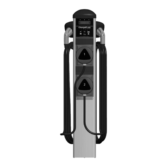
- Page 1 ® by Coulomb Technologies CT2021 ChargePoint Networked Charging Station ® Installation Guide Coulomb Technologies Inc. 1692 Dell Ave. Campbell, CA 95008-6901 USA US toll free: +1-877-370-3802 www.coulombtech.com www.mychargepoint.net Part Number: 75-001066-01 Revision: 3.0...
- Page 2 ©2011 Coulomb Technologies, Inc. All rights reserved. This material is protected by the copyright laws of the United States and other countries. It may not be modified, reproduced or distributed without the prior, express written consent of Coulomb Technologies, Inc. CHARGEPOINT is a U.S.
-
Page 3: Table Of Contents
Contents Introduction Before installing stations............................1-1 Specifications................................1-2 Wiring information ..............................1-3 Installing a Bollard Mount Before you start................................2-1 Overview of steps............................... 2-1 Step 1 - Check box for correct contents ........................2-2 Step 2 - Remove front panel ............................. 2-3 Step 3 - Remove mounting pole and base plate from body ................... -
Page 5: Introduction
NOTE: Prepare the site according to the instructions provided on page 2-5 of this document. It is also recommended that before you begin installing the CT2021 charging station, you thoroughly review the contents of this document to familiarize yourself with the contents of each box and the... -
Page 6: Specifications
ChargePoint® Charging Stations Specifications Electrical Input Input Power 7.2 kW (x 2) Input Voltage 208/240 VAC Input Current 30 A (x 2) Input Power Connections Two independent 40 A branch circuits, each providing Line 1 and Line 2. A single protective Earth conductor. -
Page 7: Wiring Information
Introduction Wiring information NOTE: Requires two dedicated circuits, each with its own 40 A breaker. LEVEL 2 CORE SEE INSTALLATION GUIDE. Input: 208/240 VAC, 60HZ, 30A (X2), 1Ø Use copper condutors only. Input terminal recommended tightening torque: 18.5 in.-lbs (2.1Nm) Input terminal wire size range: 6 to 10 AWG (13mm²... -
Page 9: Installing A Bollard Mount
• #2 Phillips screwdriver • #2 Slotted screwdriver Overview of steps ® Installing the CT2021 ChargePoint Charging Station’s body assembly involves a few simple steps: 1. Check box for correct contents (see page 2-2) 2. Remove front panel (see page 2-3) 3. -
Page 10: Step 1 - Check Box For Correct Contents
ChargePoint® Charging Stations Step 1 - Check box for correct contents ® The CT2021 ChargePoint Charging Cable hangers Station’s bollard mount assembly ships in a box containing: Body • Body* • Mounting pole* • Base plate* • Front panel* • Cable hangers (2) •... -
Page 11: Step 2 - Remove Front Panel
Installing a Bollard Mount Step 2 - Remove front panel To remove the front panel: Loosen the two screws on the • Using a T25 Torx driver, loosen the filler panel and two captive screws in the filler slide upwards to panel. -
Page 12: Step 3 - Remove Mounting Pole And Base Plate From Body
ChargePoint® Charging Stations Step 3 - Remove mounting pole and base plate from body To remove the mounting pole/base plate from the body: • Use the supplied allen wrench to loosen the four set screws (two on Loosen the each bracket). -
Page 13: Step 4 - Install J-Bolts And Conduit
Installing a Bollard Mount Step 4 - Install J-Bolts and conduit Install J-Bolts and conduit into concrete Conduit must extend as illustrated. Use the supplied base 12-24” (30-61 cm) above plate template to ensure correct the concrete (check local codes) alignment. -
Page 14: Step 5 - Mount Base Plate/Pole Assembly
ChargePoint® Charging Stations Step 5 - Mount base plate/pole assembly To mount the base plate/pole assembly: • Pull all three wires up through the conduit and the mounting pole. • Place the base plate/mounting pole assembly over the wiring conduit and attach the base plate... -
Page 15: Step 6 - Install Body
Installing a Bollard Mount Step 6 - Install body To re-install the body: • Slide the body over the mounting pole and base plate. • Ensure the body is level. • Secure the body to the mounting pole by tightening the four set screws using the supplied allen wrench. -
Page 16: Step 7 - Connect Wires To Wiring Terminals
• Requires two dedicated circuits, each with its own 40 A breaker. • Use copper conductors only. • Do NOT provide GFCI protection at panel. The CT2021 has built-in GFCI protection. • In areas with frequent thunder storms, add surge protection at the service panel for all circuits. -
Page 17: Step 8 - Replace Front Panel
Re-attach the ground wire to its tab You have now finished installing the bollard mounting and top assembly for ® the CT2021 ChargePoint Charging Station’s body assembly. You are ready to install the holsters and cable assemblies. See Chapter 3. -
Page 19: Installing The Holsters And Cable Assemblies
Overview of steps ® Installing the ChargePoint Charging Station’s holsters and cable hangers involves a few simple steps: 1. Check boxes for correct contents (see page 3-2) 2. Attach holsters/cable hangers to body assembly (see page 3-3) 3. -
Page 20: Step 1 - Check Boxes For Correct Contents
ChargePoint® Charging Stations Step 1 - Check boxes for correct contents ® The ChargePoint Charging Station’s cable Cable Assembly 1 \ Left Holster: assemblies/holsters ship in two boxes. Each box contains: • Holster • Cable assembly • Screws (3) - DISCARD THESE* •... -
Page 21: Step 2 - Attach Holsters/Cable Hangers To Body Assembly
Installing the holsters and cable assemblies Step 2 - Attach holsters/cable hangers to body assembly Align the right holster with the cable Loosely fasten hanger and attach as follows: these three screws • Insert the three screws/washers to attach the cable hanger/holster to the main body but do not tighten. -
Page 22: Step 3 - Install Cable Assembly 2
ChargePoint® Charging Stations Step 3 - Install cable assembly 2 Slide cable assembly 2 into the body all the way until it is flush with the top of the front panel. IMPORTANT! When sliding the cable assembly into the body, ensure... - Page 23 Installing the holsters and cable assemblies Step 3 - cont’d To connect the cable assembly: • Plug the cable assembly’s rectangular connector into the body assembly’s terminal block, ensuring it is fully seated. • Connect the circular connector (that hangs down from the upper terminal block) to the cable assembly, as follows: •...
-
Page 24: Step 4 - Install The Filler Panel
ChargePoint® Charging Stations Step 4 - Install the filler panel Slide the filler panel into the body assembly until it is flush with the top of cable assembly 2, as illustrated. NOTE: The filler panel is included in the shipping box for the bollard mount (see... -
Page 25: Step 5 - Install Cable Assembly 1
Installing the holsters and cable assemblies Step 5 - Install cable assembly 1 Slide cable assembly 1 into the body all the way until it is flush with the top of the filler panel, as illustrated. - Page 26 ChargePoint® Charging Stations Step 5 - cont’d Plug the cable assembly’s rectangular connector into the left receptacle on the body assembly’s terminal block, ensuring it is fully seated. IMPORTANT! Do not insert the charging station’s SAE J1772 connector into the holster until after installing the head assembly and powering up the charging station.
-
Page 27: Installing The Head Assembly
In addition, you must complete the installation of the body assembly, the holsters, and the cable assemblies (see previous chapters). Overview of steps ® Installing the ChargePoint Charging Station’s head assembly involves a few simple steps: 1. Check box for correct contents (see page 4-2) 2. Slide head assembly into body (see page 4-3) 3. -
Page 28: Step 1 - Check Box For Correct Contents
ChargePoint® Charging Stations Step 1 - Check box for correct contents Head assembly ® The ChargePoint Charging Station’s head assembly ships in a box containing: • Head assembly • Front cover plate • Spare provisioning label (a duplicate label has been attached to the head... -
Page 29: Step 2 - Slide Head Assembly Into Body
Installing the head assembly Step 2 - Slide head assembly into body Slide the head assembly into body far enough to connect the wiring, then: • Connect the circular connector (without the Ground wire) to the connector on the terminal block labeled Serial 2, as follows: •... -
Page 30: Step 3 - Verify That The Station Operates Correctly
ChargePoint® Charging Stations Step 3 - Verify that the station operates correctly Before securing the head assembly, follow these instructions to ensure that the charging station is fully operational: • Turn on the main power to ensure that the head assembly powers up. When the circuit is live and the head assembly’s wiring is connected, a sequence of power-up messages will be displayed. -
Page 31: Step 4 - Secure Head Assembly And Filler Panel
Installing the head assembly Step 4 - Secure head assembly and filler panel Using a T25 Torx driver, secure the head assembly to the body by tightening the two captive tamper-resistant security screws. Then tighten the two captive screws on the filler panel. -
Page 32: Step 5 - Install Front Cover Plates
ChargePoint® Charging Stations Step 5 - Install front cover plates NOTE: An FCC label has been applied to one of the front cover plates—install this cover plate over the head assembly. Install the cover plate without the FCC label over the filler panel. -
Page 33: Step 6 - Arrange For Station Provisioning
Step 6 - Arrange for station provisioning After a charging station has been physically installed, it is ready to be provisioned. Provisioning is the act of connecting the charging station to the ChargePoint network and establishing its network identity. In other words, you provision a station to “go live”... -
Page 35: Troubleshooting
Troubleshooting The station’s display To troubleshoot a CT2021, you’ll need to pay attention to the messages that are displayed on the two-line display. The display sequentially shows the name of the charging station and the current state of each of its ports. -
Page 36: Understanding Error Messages
ChargePoint® Charging Stations Understanding error messages The following pages describe the error messages that can occur on a CT2021 charging station. If one of the LEDs above the charging station’s display illuminates RED, read the display for information about the type of error that has occurred. - Page 37 Troubleshooting Ground fault errors The following ground fault errors can occur during charging, or when attempting to begin a charging session: #1: SUSPENDED GROUND FAULT / AUTO RE-TRY IN 00:mm:ss Cause/Other Symptoms: The station detected a ground fault during a charging session. The left or right LED will flash RED and the station will not charge.
- Page 38 ChargePoint® Charging Stations User errors The following errors occur as a result of an inappropriate action that was performed by a person using the charging station. #1: DISABLED BREAKAWAY Cause/Other Symptoms: The cable assembly was subjected to a strong pulling force and has detached (as part of the station’s safety features).
- Page 39 Troubleshooting Other errors The following errors occur as a result of a potential equipment failure or utility failure. #1: FAULT RELAY STUCK OPEN / FOR ASSISTANCE CALL ... Cause/Other Symptoms: When attempting to charge a vehicle, this message is displayed if the relay is stuck open.
-
Page 40: Checking Voltages
ChargePoint® Charging Stations Checking voltages A solenoid type voltage tester (sometimes referred to as a “Wiggy”) should be used to check the charging station’s voltages on each terminal block. This type of tester LEVEL 2 CORE will draw sufficient current to expose a SEE INSTALLATION GUIDE. -
Page 41: Appendix A: Limited Product Warranty
COULOMB TECHNOLOGIES INC. LIMITED PRODUCT WARRANTY This Limited Product Warranty applies to you, a customer who has purchased COULOMB’s ChargePoint™ Networked Charging Stations and/or related products (“Products”) from COULOMB TECHNOLOGIES, INC. (“COULOMB”) or one of its authorized distributors and not for resale. - Page 42 ChargePoint® Charging Stations Third Party Products The above Limited Warranty and Five-Year Extended Warranty are exclusive of products manufactured by third parties (“Third Party Products”). If such third party manufacturer provides a separate warranty with respect to the Third Party Product, COULOMB will include such warranty in the packaging of the COULOMB Product.
- Page 43 Limited Product Warranty Some states or jurisdictions do not allow the exclusion or limitation of incidental or consequential damages, so the above limitation or exclusion may not apply to you. THIS LIMITED PRODUCT WARRANTY GIVES YOU SPECIFIC LEGAL RIGHTS AND YOU MAY ALSO HAVE OTHER RIGHTS WHICH VARY FROM STATE TO STATE OR JURISDICTION TO JURISDICTION.
- Page 48 Coulomb Technologies Inc. 1692 Dell Ave. Campbell, CA 95008-6901 USA US toll free: +1-877-370-3802 www.coulombtech.com www.mychargepoint.net...
Need help?
Do you have a question about the CT2021 and is the answer not in the manual?
Questions and answers