
Related Manuals for Aaeon GES-2200F


Summary of Contents for Aaeon GES-2200F
- Page 1 G r e e n E m b e d d e d S y s t e m G E S - 2 2 0 0 F GES-2200F Green Embedded System 2.5” SATA Hard Disk Drive Bay 2 Gigabit Ethernet Ports/ 10 COM / 8 USB2.0 GES-2200F Manual 1st Ed. January 2011...
- Page 2 AAEON assumes no liabilities resulting from errors or omissions in this document, or from the use of the information contained herein. AAEON reserves the right to make changes in the product design without notice to its users.
- Page 3 G r e e n E m b e d d e d S y s t e m G E S - 2 2 0 0 F Acknowledgments All other products’ name or trademarks are properties of their respective owners. Award is a trademark of Award Software International, Inc.
- Page 4 G E S - 2 2 0 0 F Packing List Before you begin installing your card, please make sure that the following materials have been shipped: • GES-2200F Bare Bone • Product CD for manual (in PDF format) and drivers • AC/DC Power Adapter If any of these items should be missing or damaged, please contact your distributor or sales representative immediately.
-
Page 5: Table Of Contents
G r e e n E m b e d d e d S y s t e m G E S - 2 2 0 0 F Contents Chapter 1 General Information 1.1 Introduction..............1-2 1.2 Features ..............1-3 1.3 Specifications ............ - Page 6 G r e e n E m b e d d e d S y s t e m G E S - 2 2 0 0 F 2.17 SATA Power Connector (CN8) ......2-13 2.18 ATX Power +12V Connector (CN9) ...... 2-13 2.19 COM7~10 RS-232 Serial Port Connector (CN10) 2-13 2.20 Front Panel Connector (CN11) ......
- Page 7 G r e e n E m b e d d e d S y s t e m G E S - 2 2 0 0 F B.2 Memory Address Map..........B-4 B.3 IRQ Mapping Chart ..........B-5 B.4 DMA Channel Assignments .........B-5...
-
Page 8: Chapter 1 General Information
G r e e n E m b e d d e d S y s t e m G E S - 2 2 0 0 F Chapter General Information 1- 1 Chapter 1 General Information... -
Page 9: Introduction
This compact GES-2200F equipped with one internal 2.5” Hard Disk Drive with SATA 3.0 Gb/s interface. In addition, it features 10 COM ports and eight USB2.0 ports. Furthermore, the GES-2200F deploys single view VGA and optional TPM1.2... -
Page 10: Features
G r e e n E m b e d d e d S y s t e m G E S - 2 2 0 0 F 1.2 Features Compact Size, Fanless Platform Onboard Intel® Atom™ N450/D410/D510 Processor + ICH8M 200-Pin DDR2 533/667 DIMM x 2 (Up To 4 GB) Realtek RTL 8111C 10/100/1000Base-TX x 2... -
Page 11: Specifications
G r e e n E m b e d d e d S y s t e m G E S - 2 2 0 0 F 1.3 Specifications ® Onboard Intel Atom™ N450/D410/D510 ® Intel Atom™ N450/D410/D510 + Chipset ICH8M D-Sub 15 x 1... - Page 12 G r e e n E m b e d d e d S y s t e m G E S - 2 2 0 0 F Power-in Others — PCIe — — Expansion Mini Card Mini PCI — Others Power LED x 1, HDD LED x 1 Front...
-
Page 13: General System Information
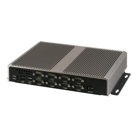
G r e e n E m b e d d e d S y s t e m G E S - 2 2 0 0 F 1.4 General System Information Front Panel Rear Panel 1- 6 Chapter 1 General Information... - Page 14 G r e e n E m b e d d e d S y s t e m G E S - 2 2 0 0 F Chapter Hardware Installation Chapter 2 Hardware Installation...
-
Page 15: Location Of Jumpers And Connectors
G r e e n E m b e d d e d S y s t e m G E S - 2 2 0 0 F 2.1 Location of Jumpers and Connectors Main board Chapter 2 Hardware Installation... - Page 16 G r e e n E m b e d d e d S y s t e m G E S - 2 2 0 0 F Chapter 2 Hardware Installation...
- Page 17 G r e e n E m b e d d e d S y s t e m G E S - 2 2 0 0 F COM Port Function Board: PER-T204 Chapter 2 Hardware Installation...
-
Page 18: Mechanical Drawing
G r e e n E m b e d d e d S y s t e m G E S - 2 2 0 0 F 2.2 Mechanical Drawing Chapter 2 Hardware Installation... - Page 19 G r e e n E m b e d d e d S y s t e m G E S - 2 2 0 0 F Chapter 2 Hardware Installation...
-
Page 20: List Of Jumpers
G r e e n E m b e d d e d S y s t e m G E S - 2 2 0 0 F 2.3 List of Jumpers The board has a number of jumpers that allow you to configure your system to suit your application. - Page 21 G r e e n E m b e d d e d S y s t e m G E S - 2 2 0 0 F CN11 Front Panel Connector KBMS1 PS2 Keyboard/Mouse Connector COM1 RS-232 & COM2 RS-232/422/485 Serial COM1 Port Connector COM3...
-
Page 22: Setting Jumpers
G r e e n E m b e d d e d S y s t e m G E S - 2 2 0 0 F 2.5 Setting Jumpers You configure your card to match the needs of your application by setting jumpers. -
Page 23: Lcd Voltage Selection (Jp1)
G r e e n E m b e d d e d S y s t e m G E S - 2 2 0 0 F 2.6 LCD Voltage Selection (JP1) Function +3.3V (Default) 2.7 LCD Backlight Control Selection (JP2) Backlight Control Function Chips control... -
Page 24: Spdif Connector (Cn2)
G r e e n E m b e d d e d S y s t e m G E S - 2 2 0 0 F Clear 2.11 SPDIF Connector (CN2) Signal SPDIF-OUT SPDIF-IN 2.12 Internal Audio 2 Channel Connector (CN3) Signal SPEAK-OUT R+ SPEAK-OUT R-... -
Page 25: Internal Ps2 Keyboard And Mouse Connector (Cn5)
G r e e n E m b e d d e d S y s t e m G E S - 2 2 0 0 F PPVCC Note: For VLCD (pin 3, 7, 27), the max. rating of each pin is 0.5A@5V. 2.14 Internal PS2 Keyboard and Mouse Connector (CN5) Signal KBDATA... -
Page 26: Sata Power Connector (Cn8)
G r e e n E m b e d d e d S y s t e m G E S - 2 2 0 0 F 2.17 SATA Power Connector (CN8) Signal +12V Note: The max. rating of Pin1 is 1A @ 12V; the max. rating of Pin4 is 1A @ 2.18 ATX Power +12V Connector (CN9) Signal Signal... -
Page 27: Front Panel Connector (Cn11)
G r e e n E m b e d d e d S y s t e m G E S - 2 2 0 0 F TXD9 CTS#9 DTR#9 RI#9 DCD#10 DSR#10 RXD10 RTS#10 TXD10 CTS#10 DTR#10 RI#10 2.20 Front Panel Connector (CN11) Signal Signal... -
Page 28: Usb Port Connector (Usb1)
G r e e n E m b e d d e d S y s t e m G E S - 2 2 0 0 F RTS#3 CTS#3 RI#3 2.23 RS-232 Serial Port Connector (COM4) Signal Signal DCD#4 RXD4 TXD4 DTR#4... -
Page 29: Usb Port Connector (Usb2)
G r e e n E m b e d d e d S y s t e m G E S - 2 2 0 0 F USBD4- USBD4+ USBD5+ USBD5- 2.27 USB Port Connector (USB2) Signal Signal USBD6- USBD6+ USBD7+ USBD7-... -
Page 30: Installing The Hard Disk Drive
G E S - 2 2 0 0 F 2.29 Installing the Hard Disk Drive Step1: Unfasten the five screws on the bottom case of the GES-2200F. Step 2: Take the two screws out of the case, and shift the HDD case horizontally and take the HDD case out of the GES-2200F. - Page 31 G r e e n E m b e d d e d S y s t e m G E S - 2 2 0 0 F Step 3: Fasten the four screws covered by damper on HDD and put the HDD back to the case 2-18 Chapter 2 Hardware Installation...
- Page 32 G r e e n E m b e d d e d S y s t e m G E S - 2 2 0 0 F Step 4: Insert the HDD case to the GES-2200F horizontally and lock the HDD case by stand-off.
- Page 33 G r e e n E m b e d d e d S y s t e m G E S - 2 2 0 0 F Step 5: Fasten the two screws to fix the HDD case Step 6: Plug the SATA cable and power cables 2-20 Chapter 2 Hardware Installation...
- Page 34 G r e e n E m b e d d e d S y s t e m G E S - 2 2 0 0 F Step 7: Fasten the five screws on the bottom case of the GES-2200F. 2-21...
-
Page 35: Chapter 3 Ami Bios Setup
G r e e n E m b e d d e d S y s t e m G E S - 2 2 0 0 F Chapter BIOS Setup Chapter 3 AMI BIOS Setup 3-1... -
Page 36: System Test And Initialization
3. The CMOS memory has lost power and the configuration information has been erased. The GES-2200F CMOS memory has an integral lithium battery backup for data retention. However, you will need to replace the complete unit when it finally runs down. -
Page 37: Ami Bios Setup
G r e e n E m b e d d e d S y s t e m G E S - 2 2 0 0 F 3.2 AMI BIOS Setup AMI BIOS ROM has a built-in Setup program that allows users to modify the basic system configuration. -
Page 38: Chapter 4 Driver Installation
G r e e n E m b e d d e d S y s t e m G E S - 2 2 0 0 F Chapter Driver Installation Chapter 4 Driver Installation... - Page 39 G r e e n E m b e d d e d S y s t e m G E S - 2 2 0 0 F The GES-2200F comes with a CD-ROM that contains all drivers your need.
- Page 40 G r e e n E m b e d d e d S y s t e m G E S - 2 2 0 0 F 4.1 Installation Insert the GES-2200F CD-ROM into the CD-ROM Drive. And install the drivers from Step 1 to Step 4 in order. Step 1 – Install Chipset Driver 1.
- Page 41 G r e e n E m b e d d e d S y s t e m G E S - 2 2 0 0 F 2. Double click on setup.exe file located in each OS folder 3. Follow the instructions that the window shows 4.
-
Page 42: Appendix A Programming The Watchdog Timer
G r e e n E m b e d d e d S y s t e m G E S - 2 2 0 0 F Appendix Programming the Watchdog Timer Appendix A Programming the Watchdog Timer... -
Page 43: Programming
GES-2200F utilizes W83627UHG chipset as its watchdog timer controller. Below are the procedures to complete its configuration and the AAEON intial watchdog timer program is also attached based on which you can develop customized program to fit your application. Configuring Sequence Description... - Page 44 G r e e n E m b e d d e d S y s t e m G E S - 2 2 0 0 F (3) Exit the W83627UHG config Mode. Undesired result may occur if the config Mode is not exited normally. (1) Enter the W83627UHG config Mode To enter the W83627UHG config Mode, two special I/O write operations are to be performed during Wait for Key state.
- Page 45 G r e e n E m b e d d e d S y s t e m G E S - 2 2 0 0 F 0: GPIO5 is inactive. 1: GPIO5 is active. 0: WDTO# and PLED are inactive. 1: WDTO# and PLED are inactive.
- Page 46 G r e e n E m b e d d e d S y s t e m G E S - 2 2 0 0 F 01h: Time-out occurs after 1 second/minute 02h: Time-out occurs after 2 second/minutes 03h: Time-out occurs after 3 second/minutes …………………………………………………..
-
Page 47: W83627Uhg Watchdog Timer Initial Program
G r e e n E m b e d d e d S y s t e m G E S - 2 2 0 0 F A.2 W83627UHG Watchdog Timer Initial Program Example: Setting 10 sec. as Watchdog timeout interval #include <stdio.h>... - Page 48 G r e e n E m b e d d e d S y s t e m G E S - 2 2 0 0 F // Set WatchDog time is 10 sec outportb(EFER_Port,0xf6); outportb(EFER_Port+1,0x0A); time is 10 sec outportb(EFER_Port,0xAA);...
-
Page 49: Appendix B I/O Information
G r e e n E m b e d d e d S y s t e m G E S - 2 2 0 0 F Appendix I/O Information Appendix B I/O Information... -
Page 50: I/O Address Map
G r e e n E m b e d d e d S y s t e m G E S - 2 2 0 0 F B.1 I/O Address Map Appendix B I/O Information... - Page 51 G r e e n E m b e d d e d S y s t e m G E S - 2 2 0 0 F Appendix B I/O Information...
- Page 52 G r e e n E m b e d d e d S y s t e m G E S - 2 2 0 0 F B.2 1 MB Memory Address Map Appendix B I/O Information...
-
Page 53: B.3 Irq Mapping Chart
G r e e n E m b e d d e d S y s t e m G E S - 2 2 0 0 F B.3 IRQ Mapping Chart B.4 DMA Channel Assignments Appendix B I/O Information...
Need help?
Do you have a question about the GES-2200F and is the answer not in the manual?
Questions and answers