Table of Contents
Advertisement
Quick Links
- 1 Technical Data
- 2 Overview of Components
- 3 Assembling the Microscope
- 4 Assembling the DIC Module and DIC Objective Prisms
- 5 Assembling the Specimen Stage
- 6 Assembling the Fluorescence Illuminator
- 7 Assembling the Incident Light Illuminator
- 8 Adjusting the Diaphragms for the Incident Light Illuminator
- Download this manual
Advertisement
Table of Contents

Related Manuals for Leica DMi8 A


Summary of Contents for Leica DMi8 A
- Page 1 Leica DMi8 A Leica DMi8 C Leica DMi8 M Installation Manual Leica Microsystems CMS GmbH Manual 11934095, Revision 1.0 from 2015-01-15 •...
- Page 2 Coyprights Copyright All rights to this documentation are held by Leica Micro- systems CMS GmbH. Reproduction of text or illustrations (in whole or in part) by print, photocopy, microfilm or other method (including electronic systems) is not allowed with- out express written permission from Leica Microsystems CMS GmbH.
-
Page 3: Table Of Contents
Contents Contents Important Notes about this Manual ......4 Text symbols and their meanings ....... 4 Safety Notes ..............6 General safety notes ............ 6 Technical data ............... 6 Overview of Components ..........8 Unpacking ..............12 Assembling the Microscope ........14 Assembling the DIC Module and DIC objective prisms ........... -
Page 4: Important Notes About This Manual
1. Important notes about thIs manual 1. Important Notes about this Manual Caution! This Installation Manual is an essential component of the product; it must be read carefully before the product is assembled, put into operation or used, and must be kept for later reference. - Page 5 1. IMPORTANT NOTES ABOUT THIS MANUAL Warning of hazardous electrical voltage! Danger of electric shock! Danger due to hot surface Warning of optical radiation! Never look directly into the light beam! Wear safety goggles! Warning of electromagnetic fi eld Warning of UV radiation! Wear safety goggles! Warning of hazardous laser radiation –...
-
Page 6: Safety Notes
Technical data Compact Leica CTR electronics box Caution! For indoor use only. Supply voltage: 100 – 240 VAC Make sure to follow the safety notes in the Leica DMi8 Frequency: 50 / 60 Hz User Manual. Power consumption: max. 150 VA Fuses: 3.15 A, slow-blowing,... - Page 7 Relative humidity: 90% up to 30°C, non-condensing Protection class: Overvoltage category: Pollution degree: Leica DMi8 A microscope (automated variants) For indoor use only. Supply voltage: 100 – 240 VAC (→ Leica CTR) Frequency: 50 / 60 Hz (→ Leica CTR)
-
Page 8: Overview Of Components
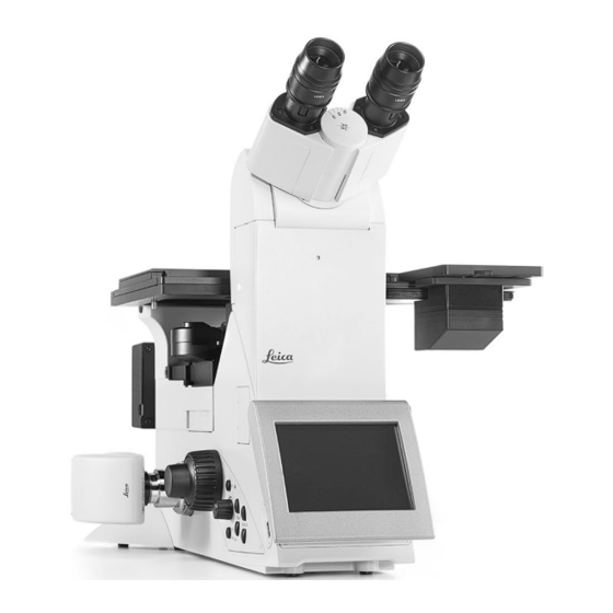
3. Overview Of COmpOnents 3. Overview of Components Fig. 1: Right side of the Leica DMi8 A Aperture diaphragm Objective turret with objectives Tube Field diaphragm Polarizer slot Eyepieces and eyepiece tubes Analyzer slot Specimen stage LED lamp housing Cover for right side-port... - Page 9 3. Overview Of COmpOnents Fig. 2: Left side of the Leica DMi8 A Motorized DIC objective prism disk Cover plate (not used) Service port Left side-port with camera...
- Page 10 3. Overview Of COmpOnents Fig. 3: Left side of the Leica DMi8 C Eyepieces and eyepiece tubes Tube Top-port with camera Cover plate (not used) Incident light turret disk Cover for left side-port Manual DIC objective prism disk LED lamp housing...
- Page 11 3. Overview Of COmpOnents Variants with transmitted light illuminator arm Fig. 4: Left side of the Leica DMi8 with tiltable transmitted light illumi- nator arm Tiltable transmitted light illuminator arm Condenser height adjustment Manual polarizer Manual condenser, alternatively: motorized condenser...
-
Page 12: Unpacking
See the chapter on "Care of the Microscope"→ for additional instructions in The Leica CTR electronics box, Leica SmartMove control el- the Instructions for Use. ement, Leica STP4000/8000 control panel, movable stages/ stage accessories and Leica EL6000 compact light source are delivered in separate packages. - Page 13 4. Unpacking Caution! Electrical components must be placed at least 10 cm away from the wall and away from flammable substances. Weight The weight of the microscope depends on the respective equipment configuration. CAUTION At a full load, the microscope weighs more than 18 kg. The user must take corresponding precautions for trans- porting the instrument.
-
Page 14: Assembling The Microscope
5. Assembling the microscope 5. Assembling the Microscope The microscope components are logically assembled in this order: • Only for microscopes with transmitted light illuminator arm (chapter 5.8-5.10): • Transmitted light illuminator arm • Condenser with condenser head • Transmitted light lamp housing • DIC module and DIC objective prisms • Specimen stage • Eyepieces • Objectives • Incident light illuminator (LED lamp housing) • Equipment for the incident light turret... -
Page 15: Assembling The Dic Module And Dic Objective Prisms
If the microscope is not equipped with DIC, please jump ahead to Chapter 5.2. In microscopes of the Leica DMi8 M series, the DIC prisms are already installed in the DIC disk (Fig. 7) below the objec- tive turret. Motorized, manually encoded and manual DIC disks are offered. -
Page 16: Assembling The Specimen Stage
5. Assembling the microscope – specimen stAges Assembling the specimen stage Fig. 12: Fixed stage There is a wide variety of available specimen stages. The accompanying figures depict a few examples. The assembly of each of these stages is identical. The stages are permanently affixed to the microscope using 3 screws (Fig. - Page 17 The mechanical stage is preadjusted at the factory. If the mechanical stage shifts out of focus when moving from right to left, this can be corrected by Leica Technical Ser- vice. Fig. 16: Inserts for mechanical stage (fixed stage) For additional examples, see special brochure • Now, remove the ordered stage insert or inserts (Fig. 16)
-
Page 18: Inserting The Eyepieces
5. Assembling the microscope – eyepiece And objectives Inserting the eyepieces Fig. 17: Eyepieces • Insert the eyepieces into the eyepiece tubes. Note: We recommend using the LAS software to teach in eye- pieces that are not included in the scope of delivery. This ensures that the total magnification specified on the touchscreen is correct. -
Page 19: Assembling The Incident Light Illuminator
21.1) on the rear side of the microscope. • Close the light guide according to the information in the Leica DMi8 A and C with motorized incident light method: Leica EL6000 manual. • Connect the cable of the lamp housing to the power sup- ply for transmitted light for the Leica CTR electronics box ("Lamp RL"... -
Page 20: Equipping The Incident Light Reflector Turret
5. Assembling the microscope – incident light turret equipment Equipping the incident light reflector turret Fig. 22: Access to turret disk Cover Caution! First, completely read through this section before you begin equipping the reflector turret disk. The reflector turret disk can be accessed from both the right side and the left side of the microscope (Fig. -
Page 21: Assembling The Polarizer And Analyzer
5. Assembling the microscope – polArizer And AnAlyzer Assembling the polarizer and analyzer Manual incident light polarizer • Remove the plug cap on the right side of the stand (be- hind the incident light turret disk (Fig. 25.1)). Fig. 25: • Insert the polarizer into the receptacle until it latches in Incident light polarizer place (Fig. -
Page 22: Assembling The Transmitted Light Illuminator Arm (Tl)
(Fig. 26.2) fits in the groove of the contact surface (Fig. 26.4). • Raise up the transmitted light illuminator arm and fasten it Fig. 27: Rear side of motorized Leica DMi8 with 4 screws (Fig. 27.1). Fastening screws on the transmitted light illuminator arm... -
Page 23: Fixed Transmitted Light Illuminator Arm
5. Assembling the microscope – trAnsmitted light illuminAtion cArrier 5.8.2 Fixed transmitted light illuminator arm Fig. 28: Condensers S40/0.45 condenser Assembling the transmitted light column S80/0.30 condenser • Attach the transmitted light illumination column (Fig. 30.1) and fasten it with 4 screws (Fig. 30.2). Attaching the condensers • Screw the S80/0.30 condenser (Fig. 28.2) or S40/0.45 condenser (Fig. -
Page 24: Assembling The Condensers For The Tiltable Transmitted Light Illuminator Arm
For the fixed transmitted light illuminator arm, see Chapter 5.8.2 → Page 23. All condensers from the Leica DMi8 series with a tiltable transmitted light illuminator arm are equipped with a 7x turret disk and can be individually equipped with the cor-... - Page 25 5. Assembling the microscope – condenser Assembling light rings Fig. 36: Condenser Condenser door • Switch the microscope off. Centering hole • Remove the condenser door (Fig. 36.1). The light ring is in- serted into one of the large receptacles of the condenser disk featuring guide grooves. • Using the adjusting key, turn the right centering screw of the condenser disk (Fig.
- Page 26 5. Assembling the microscope – condenser • Using the condenser clamp, grip the light ring to be in- Fig. 38: Inserting the prism The designation must be visible when inserted and oriented to the cen- stalled (the marking must be facing upwards and be leg- ter of the condenser disk.
- Page 27 5. Assembling the microscope – condenser Assembling IC condenser prisms Caution! • Switch the microscope off. Never press down on the spring clip. This can destroy the • Remove the condenser door (Fig. 36.1). The prism is in- clip or put the prism in an unstable position. serted into one of the large receptacles of the condenser disk featuring guide grooves.
- Page 28 5. Assembling the microscope – condenser Assembling condensers Fig. 39: Assembling the condenser on the transmitted light illuminator Assembly is the same for all S1 to S70 condensers (motor- ized or manual/encoded; not encoded for S40). • Loosen the Allen screws on the right side of the condens- er holder. • Place the condenser on top of the locking pins of the transmitted light illuminator arm and then move the con- denser to the corresponding height.
- Page 29 5. Assembling the microscope – condenser Condenser heads Assembling the polarizer There are 4 different condenser heads available: Preconfigured at the factory. S1/1.40 oil Proceed as follows when performing upgrades: S1/0.90 dry S23/0.53 Motorized condenser: S28/0.55 See the enclosed Assembly manual. Condenser head 1 and 2: Manual condenser: • Screw the spacer ring (Fig. 41.2) into the threaded hole on...
-
Page 30: Assembling The Transmitted Light Lamp Housing
• Route the cable into the cable shaft on the rear side of the transmitted light illuminator arm (Fig. 46). Fig. 47: Manually connecting the lamp housing for the Leica DMi8 Leica DMi8 M and C with manual transmitted light method: Transmitted light lamp housing connection • Connect the cable of the lamp housing to the port (Fig. -
Page 31: Wiring
• If present, connect the Leica SmartMove control element The microscope can be operated with or without an elec- or Leica STP4000/8000 control panel to one of the USB tronics box depending on its configuration. Depending on ports (Fig. 50/Fig. 51.3). the microscope configuration, different electronics boxes are available: • If necessary, connect the motorized stage to the XY-... -
Page 32: Wiring For Microscopes With Transmitted Light Illuminator Arm
5. Assembling the microscope – Wiring 5.11.1 Wiring for microscopes with transmitted light illu- Fig. 50: Rear side of compact Leica CTR electronics box Connection for lamp cable for incident light minator arm Connection for lamp cable for transmitted light... -
Page 33: Startup
6. Instrument setup– AdjustIng the dIAphrAgms Fig. 52: Adjusting the diaphragms (incident light) 6. Startup Adjusting screws for moving the field diaphragm Adjusting screws for moving the aperture diaphragm Adjusting the diaphragms for the incident light illuminator The following procedure is provided for incident light-bright field illumination. -
Page 34: Inspecting The Phase Contrast Ring
6. Instrument setup– InspectIng the phase contrast rIng Inspecting the phase contrast ring For the Leica DMi8 with tiltable transmitted light illumina- tor arm If your microscope is equipped for the use of phase con- trast, the light rings that fit the objectives are built into the condenser. - Page 35 6. Instrument setup– InspectIng the phase contrast rIng Leica DMi8 with manual condenser: Fig. 54: Condenser centering Centering holes • Select the light ring for your active objective on the con- Height adjustment denser. Prisms and phase ring centering Leica DMi8 with motorized condenser: • The correct light ring on the motorized condenser is auto- matically swung inwards. • If the light ring and the phase ring are not shown as ar- ranged in Fig.
-
Page 36: Setting The Polarizer
6. Instrument setup– settIng the polarIzer Setting the polarizer For the Leica DMi8 with tiltable transmitted light illumina- tor arm Fig. 56: Condenser with manual polarizer Start by removing the specimen from the microscope stage. Leica DMi8 with manual condenser: • Select the bright-field position on the condenser. -
Page 37: Condenser Centering
6. Instrument setup– Condenser CenterIng Condenser centering Fig. 58: Condenser centering Centering holes For the Leica DMi8 with tiltable transmitted light illumina- Height adjustment Prisms and phase ring centering tor arm Clamping screw Set the Koehler illumination for your microscope (not avail- able for S40 and S70 condensers). -
Page 38: Index
LAS software 18, 26 Condensers 23, 24, 28 LED lamp housing 10, 19 Connection for fixed transmitted light Technical data 6 Leica CTR electronics box 31, 32 illuminator arm 31 Tiltable transmitted light Leica EL6000 19 Cover for fluorescent turret disk 8... - Page 40 Copyright © Leica Microsystems CMS GmbH • Ernst-Leitz-Strasse • 35578 Wetzlar Germany 2015 • Phone (06441)29-0 • Fax (06441)29-2599 LEICA and the Leica logos are registered trademarks of Leica IR GmbH. Order Nos. of the editions in: English 11934095 Printed on chlorine-free bleached paper. III/15/M.H. Revision 1.0, issued 2015-01-15...
Need help?
Do you have a question about the DMi8 A and is the answer not in the manual?
Questions and answers