Table of Contents
Advertisement
Quick Links
Advertisement
Table of Contents

Related Manuals for Leica DM IRM


Summary of Contents for Leica DM IRM
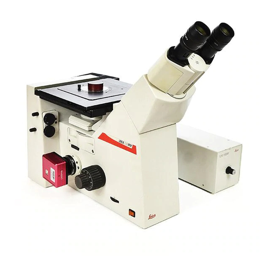
- Page 1 Leica DM IRM Inverted Research Microscope for Material Testing Instructions...
- Page 2 Issued in 1998 by: Leica Microsystems Wetzlar GmbH Ernst-Leitz-Straße D-35578 Wetzlar (Germany) Responsible for contents: MQM Marketing, Product Management Tel. +49 (0) 64 41-29 22 39 +49 (0) 64 41-29 24 64 or 22 55 e-mail Klaus.Luthardt@lmw.leica.com...
- Page 3 Copyrights All rights to this documentation and the software it describes are owned by Leica Microsystems Wetzlar GmbH. Copying of text and illustrations – in full or in part – by printing, photostat, microfilm or other techniques, including electronic systems, is only permitted subject to the express written consent of Leica Microsystems Wetzlar GmbH.
-
Page 4: Table Of Contents
Contents Important notes Tube module 1 x, magnification on this manual ....changer 1 x, 1.5 x (B) ....Intended application, Lateral photo/TV exit . -
Page 5: Important Notes
6 Care and maintenance of explosion 7 Conformity declaration Warning of hot surface There are 6 basic variants of the Leica DMIRM microscope, which can be configured individual- Explanatory note Information on equipping the microscope further Caution! Operation errors can dam-... -
Page 6: Intended Application
100 %/100 % or 50 %/50 %, 17 Adapter tube for photo/TV connection, 18 Analyser slot Intended application: The Leica DM IRM is designed for metallographi- cal test laboratories for material control and research of opaque and transparent industrial... - Page 7 1 Lamphousing mount, 2 12 V 100 W socket, 3 Mains socket, 100 % vis–100 %TV Order no. 571005 4 Potential equalisation socket, 5 Cover for transmitted light Leica DMIRM with tube optics oo/1 x, 1.5 x HC (magnification changer) with lateral photo/TV exit 100 % vis–20 %vis/80 %TV Order no.
- Page 8 Make sure that no small parts are left in the member of Leica sales or service staff. packing material. Only a few ordinary screwdrivers are required for...
- Page 9 The mains plug must only be inserted into a sult the Leica agency for your area or the main grounded outlet. factory in Wetzlar! If an extension cord is used, it must be grounded as well.
- Page 10 n.b.: The electric accessories of the microscope are not waterproof. If water gets inside them, it may cause electrical shock. Do not put the microscope and its accessories near a water tap or anywhere else where water may get inside them. n.b.: Before changing fuses or lamps, always turn the mains switch off and disconnect the mains...
-
Page 11: Of The Microscope
3.2 Assembling the lamp mount, mirror housing, lamphousing, illumination telescope 1 Insert the lamp mount or the mirror housing in the back panel and screw down with Allen screws. Make sure the guide pin of the lamp mount (7.1) engages in the back panel of the microscope (6.2). -
Page 12: Illumination Telescope
Fig. 8 Mirror housing and illumination telescope 1 Mirror switching lever, 2 Lateral lamphousing mount with fixing screw, 3 Back lamphousing mount with Allen screw, 4 Illumination telescope for gas discharge lamps Fig. 9 Lamphousing 106Z L 1 Collector adjustment, 2 Vertical lamp adjustment, 3 Horizon- tal lamp adjustment, 4 Dovetail ring mount, 5 Reflector adjust- ment (not visible) -
Page 13: Assembling And Changing The Incident Light Lamps
3.3 Assembling and exchanging the incident light lamps Exchanging the 12 V 100 W halogen lamp: Disconnect the lamp and lamphousing from the power supply. Pull out the mains plug. Lamphousing 107L Slacken the fixing screw on the cover and lift off the cover (10a.4). - Page 14 Lamphousing 106Z L* Slacken the fixing screw on the lid (11.4, 9). Pull the cut-out plug slightly out of the socket (11.11) and flip up lid (11.1). Move the collector to the front and lift the defect lamp out of the base (11.2, 11.3, 14.1). For convenience, the lamp holder can be re- moved from the lamphousing as well.
-
Page 15: The Incident Light Lamps
3.3 Assembling and exchanging the incident Lamphousing 106Z L light lamps Besides the halogen lamp, the following gas discharge lamps can be used, which each re- Assembling and exchanging Hg and Xe lamps quire different lamp mounts (13) and power units: Power units Hg and Xe lamps are powered by separate power units. - Page 16 Hg 50 Hg 100 With ignition module Fig. 13 Lamp holders for gas discharge lamps Xe 75 1 Upper clamp, 2 Seal point of the burner, 3 Lower clamp, 4, 6 Drill holes for fixing the lamp holder, 5 Sockets for cut-out plug, 7 Protective cover n.b.! 1.
- Page 17 Put the upper pin of the burner between the clamps of the flexible power supply and clamp n.b.! with screw (13.1). Unscrew the stud (13.3) in the holder slightly, in- Adjust the burner immediately after ignition. sert the lower end of the metal base and retighten To exchange the collector on the lamphousing the stud.
-
Page 18: Assembling The X/Y Stage
3.4 Assembling the 3-plate x/y stage no. 19 The 3-plate x/y stage no. 19, size 247x230 mm, adjustment range x-y 60x40 mm, is delivered in separate packaging and assembled as follows: 1. Screw the 3 Allen screws (15.2, 15.3) out of the stage support surfaces and wipe any remains of packaging or dust, etc. - Page 19 3. Screw the large clip for metallographic sam- ples into the M4 thread hole (17.4). 4. Allen screws (17.3) for plane-parallel align- ment. n.b.: Do not adjust these Allen screws. They are only for adjustment in the factory. Fig. 17 Stage inserts with accessories 5.
-
Page 20: Assembling The Tubes
3.5 Assembling the tubes: HCI B 22 Binocular tube with 45° viewing angle Field of view index up to 22 Eyepiece diameter 30 mm for HC PLAN 10x/20 or 22 eyepieces Interpupillary distance setting: 55–75 mm HCI 3T 22 Trinocular tube, 45° viewing angle Light path: 100 % vis 50 % - 50 %... - Page 21 Assembly of Leica DMR tubes: All the tubes in the Leica DMR range can be adapted with the IR HC tube adapter (23.3): e.g. Binocular observation and photo tube HC FSA 25 PE (23.1) Viewing angle 30° With side port for reflecting measurement scales and µ...
- Page 22 3 100 %/100 % switch rod, 4 Clamp screw screw for adapter/tube interface, 6 Photo/TV port Fig. 24 Leica DMR HC tubes 1 HC BSA 25, 2 HC FSA 25 P + PR, 3 Beamsplitter switch rod, 4 Mount for photo adapter tube, 5 Clamp for photo adapter tube,...
-
Page 23: Inserting The Objectives
3.6 Inserting the objectives Lift the square insert plate out of the 3-plate x/y stage (26) BD objectives (bright- and darkfield) are screwed straight into the holes with M32 x 0.75 mm thread in the objective nosepiece (26.1). They are ar- ranged clockwise from the lowest to the highest magnification. - Page 24 3.7 Inserting the reflectors and fluorescence Other reflectors: filter systems* DF reflector (30)* Mirror with centre stop for darkfield observation Remove the front cover after slackening the Allen only screws. Insert the reflectors into the dovetail mount as far Smith reflector (31)* as the stop, with the flattened end of the reflector first and the engraving underneath.
- Page 25 Fig. 29 BF reflector Fig. 32 ICR reflector 1 Neutral plane glass beamsplitter, 2 N16 neutral density filter Fig. 30 DF reflector Fig. 31 Smith reflector...
- Page 26 3.8 Inserting the ICR prism disc and the ICR objective prisms The ICR prism disc with the ICR prisms you or- dered are already assembled in the microscope at the factory. In case you want to retrofit the ICR prism disc, please proceed as follows: Remove the front cover under the objective Fig.
-
Page 27: And Analysers
The 0° = east-west vibration direction is intended Fig. 37 Incident light polariser, 90° rotatable with rotatable whole-wave compensator for use on the DM IRM. 1 Polariser slide, 2 Dial for setting polariser, 3 Knurled button Preselect the vibration direction 0° = east-west for rotating the whole-wave compensator on the dial (37.2). - Page 28 Incident light polariser L ICR/P, with whole- wave compensator, reversible by 180° (38) For use on the DMIRM with fixed vibration direc- tion 0° = east-west. The whole-wave compensator is fixed in the 45° diagonal position and can be activated or deac- tivated by turning the polariser slide over by 180°.
-
Page 29: The Condensers
3.10 Assembly of the transmitted light illumina- tion column and the condensers* Slacken the 2 recessed head screws (41.2). Remove the cover (41.1) from the back of the stand. Wipe the mount surface (42.3) with a dry cloth. Tilt the transmitted light illumination column (42.1) Fig. - Page 30 Lamphousing for transmitted light illumination (44) for 12 V 100 W halogen lamps with single-lens aspherical collector and heat protection filter is an integral part of the transmitted light illuminati- on column. Assembling and changing the 12 V 100 W halogen lamp Disconnect from the power supply.
- Page 31 Condenser range: See Leica DMIRB manual Assembling the 0.30 S70 condenser* Tilt the TL illumination column to the back (46.1). Insert the 0.30 S70 condenser (46.4), with the top pointing towards the microscope stage, into the dovetail guide of the illumination column (46.2) from below.
- Page 32 push the condenser back as far as the stop. Retighten the clamp screw (49.5) slightly. Fig. 48 Assembly of condenser holder 1 Condenser holder in working position for condenser 0.53 S23 (upper edge of condenser holder coincides with condenser height marking S23), 2 Dovetail guide, 3 Condenser height markings S1, S23 and S70, 4 Condenser holder, 5 Clamp screw for securing the condenser holder, 6 Clamp screw for field diaphragm module, 7 Transmitted light lamphousing...
-
Page 33: Light Illumination Column And
Secure with clamp screw (50.3). Assembly of filters and filter holder The Leica DM IRM is equipped with a holder with spaces for 3 filters with 40 mm diameter. The filters are already fitted into the holder at the factory. - Page 34 Fig. 50 Assembly of field diaphragm 1 Field diaphragm module, 2 Field diaphragm adjustment, 3 Clamp screw for securing the field diaphragm module Fig. 52 Assembly of the filter holder for 3 filters Fig. 51 Assembly of filters 1 Clamp screws for securing the filter holder...
-
Page 35: Start-Up And Operation
4 Start-up and operation 4.1 Coaxial coarse and fine focusing n.b.! The coarse drive (53.1) and the fine drive (53.2) Before rotating the nosepiece and changing act on the objective nosepiece and the objec- tives. objectives of 50 x–250 x magnification, lower the The sample is focused by raising or lowering the coarse and fine focus drive if possible, to avoid contact between the front lens and the stage in-... - Page 36 Fig. 53 Side view of the microscope 1 Coarse drive, 2 Fine drive with scale division, 3 Objective nosepiece with nosepiece focusing, 4 Specimen stages with 3- point support Fig. 54 Specimen stage with inserts 1 Inner hole of the stage insert...
-
Page 37: Observation Tubes
4.2 Observation tubes This is done by pulling the eyepiece tubes apart or pushing them together with both hands until Fig. 55 the two part images in the microscope superim- HCI B 22 pose. Binocular tube Only one single, circular, clear image is seen. 45°... - Page 38 Fig. 55 Binocular tube HCI B 22 1 Eyepiece tubes, 2 Eyepieces, 3 Anti-glare protection (push- back eyecups) Fig. 56 Trinocular tube HCI 3T 22 1 Photo/TV exit, 2 Switch rod for light path...
-
Page 39: Tube Module 1 X, Magnification
4.3 Tube module 1x, magnification changer After the Bertrand lens has been engaged, the 1 x, 1.5 x or 1 x, 1.5 x Bertrand lens focusing lever (58.2) can be operated to focus and/or centre the image of the lamp filament or Our product range includes 3 tube lens systems aperture diaphragm, isogyre cross, phase rings, which are effective at all the light exits of the... -
Page 40: Lateral Photo/Tv Exit
4.4 Lateral photo/TV exit There are 2 alternative configurations for the lateral photo/TV exit (1.12). Either configuration with light path 100 % visual or 20 % visual/80 % side exit or configuration with light path 100 % visual or 100 % side exit Position of switching rod (59.1), pulled out = side exit switched on Fig. -
Page 41: Optical Outfits
* - = designed for specimens with or without a coverglass 0 = designed for specimens without a coverglass The DM IRM microscope is based on tube length Fig. 61 Optical equipment ∞ 1 N PLAN objective series for brightfield, M25x/0.75 screw... - Page 42 Only infinity corrected Leica objectives may be used. Earlier-type infinity Leica objectives can only be used if they are brightfield objectives and com- bined with the spacer ring 32/RMS. Depending on the year the objective was made, the engraved magnifications may deviate by the factor 0.8 x, as the new DMIRM is designed for a...
- Page 43 Objectives for incident light brightfield, polarisation contrast, interference contrast * n.b.: Brightfield objectives with M25 x 0.75 mm or RMS screw thread need a spacer for adaption to the objective nosepiece with M32 x 0.75 mm thread (27) with N PLAN objectives with M25 x 0.75 screw thread ∞/- N PLAN 2.5 x/0.07...
- Page 44 Objectives with long working distances with 1.8 mm quartz glass coverglass correction (M25x0.75) ∞/1.8Q B PLAN H 20 x/0.40 FWD* 12.60 mm Order no. 566003 ∞/1.8Q B PLAN H 40 x/0.60 FWD* 7.10 mm Order no. 566004 Spacer ring 32/25 Order no.
- Page 45 The eyepiece field of view no. 22 should not be exceeded for the Leica DMIRM. Using eyepieces with higher field numbers (e.g. 25) can lead to vignetting at the edge of the image.
-
Page 46: Eyepiece Graticules
4.6 Eyepiece graticules* For calibrating the graticules, we recommend: Incident light stage micrometer, Graticules for length measurements and grain 1 mm = 100 divisions Order no. 563011 and particle measurements Our product range comprises the following grati- cules: • Graticule 10 mm/100 divisions Order no. - Page 47 Graticule 10 mm/100 divisions (63)* For graticules with a scale of 10 mm/100 divisi- ons, one scale interval is roughly equivalent to the following lengths in the specimen plane: 0.02 mm = 20 µm for 5 x objective 0.01 mm = 10 µm for 10 x objective 0.005 mm = 5 µm for 20 x objective 0.002 mm = 2 µm for 50 x objective 0.001 mm = 1 µm for 100 x objective...
- Page 48 Inserting the graticules: 10x/20M 10x/25M 10x/20 10x/22M PHOTO The graticules have a diameter of 26 mm and can only be inserted in the eyepieces HC PLAN 10x/20/22/25 with type M adjustable eyelens. The second eyepiece in the tube should also have a type M adjustable eyelens.
-
Page 49: Switching On And Adjusting
4.7 Switching on and adjusting the 12 V 100 W halogen lamp Switch on the power supply with the toggle switch (67.1) and adjust the light intensity by ro- tating the dial at the side. Rotating the dial clockwise increases intensity and vice versa. - Page 50 4.8 Centration of the 12 V 100 W, Hg, Xe lamps* 6. Then adjust the screw for vertical adjustment (68.3) to align the filament image vertically in Lamphousing 107/2 for 12 V 100 W halogen lamp the centre of the pupil. This lamphousing is permanently set and does not require centration.
- Page 51 (72c). 1. Put a piece of paper or non-shiny piece of Leica packaging on the specimen stage and roughly focus the surface with a low-magnifi- cation objective.
-
Page 52: Hg 100 W And Xe 75 W
Centration of Xe or Hg gas discharge lamps move the reflection until it is symmetrical with the direct image (71a, b, c). The V-shaped emissions of the arcs of the direct n.b.! image and the reflection can be superimposed. Never look straight into the light path! Remember the risk of glare when switching to Caution: the BF or Smith reflector! -
Page 53: Centring The Aperture And Field Diaphragm
4.9 Centring the aperture and field diaphragm Normally, the field diaphragm is opened until it just disappears out of the field of view. Centring the aperture diaphragm When imaging reduced picture diagonals such as in photomicrography or TV microscopy, the Turn a low to medium objective magnification field diaphragm can be narrowed to frame the 10x/20x into the light path and focus a strongly... - Page 54 4.10 Use of light filters* VG 9 green filter for contrast enhancement, 3 light filters are permanently integrated in the fil- order no. 514041 ter magazine (73). Neutral density filter 0.2% These are moved into the light path via 3 swit- for light attenuation without influencing the ching levers (74.1).
- Page 55 Fig. 74 Side view of microscope 1 3 levers for operating filters Fig. 75 Intermediate filter holder 1 Light filters, 50 mm diameter, 2 Intermediate piece with filter spaces...
-
Page 56: Examinations In Incident Light
4.11 Examinations in incident light brightfield, Then the illumination aperture is equal to the darkfield, polarisation contrast, interfer- objective aperture (77.1). ence contrast This can be checked by looking through the empty eyepiece tube after removing one of the Please proceed as follows for selecting and set- eyepieces (77). - Page 57 Fig. 77 Setting the aperture diaphragm (entrance pupil of the objective) 1 Aperture diaphragm open, 2 Aperture diaphragm closed by , 3 Aperture diaphragm closed...
- Page 58 Incident light darkfield* To match the image intensity when switching to brightfield, slot a neutral density filter onto the BF Special darkfield objectives (BD type) (78.1) with reflector. (29.2) built-in annular mirror and annular lenses are required for incident light darkfield. These objectives have larger outer diameters and screw thread M32x0.75mm.
- Page 59 Polarisation contrast* When the compensator is activated, pol-optic colour contrast with a fixed retardation of one Adjust the microscope as for brightfield examina- wavelength is produced (1st order red). tions. Incident light polariser R/P in slide (79) n.b.: Adjust the polariser to the vibration direction 0° = east-west (polariser can be plugged in different When using gas discharge lamps (Hg, Xe), make positions)
-
Page 60: Interference Contrast
Incident light interference contrast ICR Choice of ICR prisms: Adjust the microscope as for brightfield examina- The right type of prism for the particular objective tions. is engraved on the objective sleeve. The Smith reflector (31) is an excellent alterna- e.g. -
Page 61: Examinations In Incident
4.12 Examinations in incident light fluorescence Select a filter cube to suit the excitation and emission spectrum of the specimen and switch into the light path with the reflector turret (76.1). All polarisation-optic components, such as the polariser, analyser and ICR prisms must be re- moved from the light path. -
Page 62: Examinations In Transmitted Light
4.13 Examinations in transmitted light Adjusting the height of the condensers: There are markings (S70, S23 and S1, 48.3) on the transmitted light illumination column for correct setting of the condenser height. After slackening the screw with the supplied hexagonal screwdriver, move the condenser or condenser holder you are using until its upper edge is flush with the relevant marking on the illu- mination column. - Page 63 Setting Koehler illumination Turn the 10 x objective into the light path and focus the specimen. 1. Turn the condenser disc (84.3) to the ”H“ clickstop position (H = Hellfeld= brightfield) 2. Close the field diaphragm (48.8) 3. Adjust the height of the condenser (82.3) until the edge of the field diaphragm is sharply focused.
-
Page 64: Length Measurements
4.14 Length measurements Eyepiece graticules or, with the slide overlay device, measurement scales can be used for taking length measurements in the DM IRM. For measurements on the TV screen we recom- mend the video measurement crosshair Leica DMMFK2. For the eyepiece graticules with scale 10 mm =... -
Page 65: Accessories
5 Accessories 5.1 Inserting and working with the slide over- 1 2 3 45 6 7 8 lay device and macro device The devices for slide overlay and macroscopy can only be used with the HC FSA 25PE tube. Slide overlay device: Mount the reflection optics (87.3) onto the tube flange (87.1) with the coupling ring;... - Page 66 – Standard circle and reference length for grain An image cannot be obtained without the reflec- size measurements tion optics. – Standard picture series for ASTM-E-112 grain Like the slide overlay device, the macro overlay size measurements only works in the 50/50 beamsplitter position You can make your own masks with any meas- (switch rod in middle position) of the FSA 25 PE urement and comparison line patterns, quality...
-
Page 67: Macro Device
The total magnification at the 35 mm camera of the DM LD is therefore 0.32 x. 1 2 3 4 5 6 7 8 10 11 The total magnification can be roughly calcula- ted with the scale divisions on the macrodual zoom: The following factors have to be multiplied for this:... -
Page 68: Photomicro Equipment
5.2 Connections for TV cameras and photo- micro equipment All the variants of the Leica DMIRM stand have a photo/TV exit on the left side (90). There are also photo/TV exits in the trinocular tubes for vertical adaption of camera systems. - Page 69 If using the magnification changer, e.g. 1.5 x (57.1), the above formula must also be multiplied by the factor of the magnification changer or zoom. The following Leica microscope camera systems are optically and mechanically compatible for photomicrography: Leica MPS 30...
-
Page 70: Care And Maintenance
Cleaning agents of un- known composition should be tested on an All Leica instruments are manufactured and inconspicuous part of the microscope. Painted or tested with extreme care. If you do have cause plastic surfaces must not be tarnished or etched. -
Page 71: Wearing And Spare Parts
Leica DM IRM Main wearing and spare parts, tools Order no. Component Used for Part no. Spare lamps 500 974 Halogen lamp 12V 100W Lamphousing 106 z L, 107 L 500 137 Ultra high pressure Hg lamp Lamphousing 106 z L... -
Page 72: Conformity Declaration
European Union. This declaration will cease to be valid if the instrument is modified without our consent. Product name: DM IRM Instrument type: Light microscope Instrument no.: 090-133.701 to 706... - Page 73 Leica Microsystems Wetzlar GmbH Tel. +49 (0) 64 41-29 0 Ernst-Leitz-Strasse Fax +49 (0) 64 41-29 25 99 D-35578 Wetzlar (Germany) http://www.leica.com...
Need help?
Do you have a question about the DM IRM and is the answer not in the manual?
Questions and answers