
Related Manuals for SKC 210-1000 Series


Summary of Contents for SKC 210-1000 Series
- Page 1 210-1000 Series Operating Instructions SKC Inc. 863 Valley View Road Eighty Four, PA 15330 USA Form 37717 Rev 1406...
-
Page 3: Table Of Contents
Table of Contents Description ....................1 Performance Profile ..................2 Battery Installation/Charging ..............4 Installing/Replacing the Battery Pack ....................4 Battery Pack Charging System......................6 Charging the Battery Pack........................6 Charging Fault ..........................7 FAIL Display .............................7 Determining Battery Charge Level ....................8 Extended Runs Using the Charger ....................8 Introduction .................... -
Page 5: Description
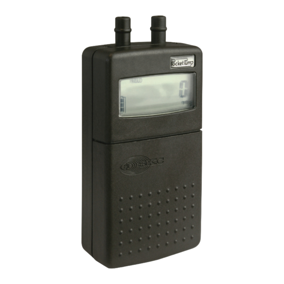
Description SKC Pocket Pump is an advanced low flow sample pump combining light weight and compact design with PC compatibility. When used with SKC sampling media such as sorbent sample tubes, the Pocket Pump is efficient and accurate for performing TWA, STEL, and Ceiling sampling for organic gases and vapors. -
Page 6: Performance Profile
Performance Profile Flow Range in Constant Flow Mode: 20 to 225 ml/min Accuracy Variance Between LCD Reading and Actual Flow Rate (after calibration): 20 to 225 ml/min ± 5% Constant Flow Compensation Range (inlet only): 20 to 225 ml/min up to 20 inches water back pressure Flow Control: Holds constant flow to ±... - Page 7 Performance Profile Timer: 1 to 9999 min display ± 1% accuracy Flow Fault: If the pump is unable to compensate for longer than 15 seconds due to excessive back pressure, the pump enters FLOW FAULT mode. The pump goes into HOLD, the fault icon appears on the display, and the accumulated run time display is frozen and retained.
-
Page 8: Battery Installation/Charging
Battery Installation/Charging Installing/Replacing the Battery Pack To enhance battery life, SKC ships battery packs separate from the pump. Completely charge a new battery pack detached from the pump before installing. Completely charge the new battery pack detached from the pump (see page 6). - Page 9 (see page 6). Do not charge or operate the pump with the charger in hazardous locations. Use only the SKC-approved battery pack designated for the Pocket Pump to ensure reliable performance and to maintain the SKC warranty and UL Listing for intrinsic safety.
-
Page 10: Battery Pack Charging System
Do not charge or operate the pump with the charger in hazardous locations. Ensure the computer interface port is covered before, during, and after charging. Failure to follow warnings and cautions voids any warranty. The battery pack may be kept on the SKC-approved charger for an Note: indefinite time. -
Page 11: Charging Fault
If FAIL still displays, there is a fault in the pump electronics. Send the pump to SKC for repair. Use only SKC-approved batteries to ensure reliable performance and intrinsic safety. Using a non-approved charger voids any warranty and could damage the pump... -
Page 12: Determining Battery Charge Level
Battery Installation/Charging Determining Battery Charge Level • The pump will operate for up to 12 hours with a NiMH battery (eight hours with NiCad) at a flow rate of 200 ml/min and back pressure of 10 inches of water. Pump operation time will increase as flow rate and back pressure rates are decreased. -
Page 13: Introduction
Introduction Interpreting Pump Operating Terms In this manual, “run time data” refers to all the terms listed below: FLOW: Flow rate in milliliters per minute (ml/min) VOLUME: Total volume of air in milliliters (ml) or liters (L) since reset PRESSURE: Pump back pressure measured in inches (ins) of water or millimeters (mm) of Hg TEMP: Temperature of incoming air in C or F... -
Page 14: Setup
Setup Operating the Keypad The Pocket Pump operates by pressing various sequences of the three keypad buttons located beneath the sliding cover. Operate the Pocket Pump with the follow- ing key sequences: Pocket Pump Keypad Star Button • Scrolls through run time data and setup options displayed on the LCD Up and Down Arrow Buttons ... -
Page 15: Determining Pump Operating States
Setup Determining Pump Operating States • The pump is sampling and run time data is updated continuously in memory. HOLD • The pump is not sampling and run time data is stored. Hold displays on the LCD. • Temperature and back pressure readings are still active and shown on the LCD. -
Page 16: Setting Up The Pump
Setup Setting Up the Pump To activate the pump: • Press any keypad button. The LCD will show the pump serial number for two seconds followed by a firmware revision number. To obtain run time data: • Press the button repeatedly to scroll through run time data. To reset the data display to zero: •... - Page 17 Setup To change pump operating mode (constant flow or constant pressure): • With the pump running, press: [] to place in HOLD, to enter Setup, and The display will now show the new operating mode. For information on operating the pump in constant pressure mode, see Advanced Operation on page 21.
- Page 18 Setup To change the temperature scale display: • In enhanced display and with the pump running, press: [] to place in HOLD, to enter Setup, and [] Press to scroll to the temperature display. The display will show the newly selected temperature scale.
-
Page 19: Operation
2. Set the pump for Constant Flow mode (see pages 12 and 13). 3. Using a length of tubing, connect the pump inlet to a representative sorbent tube using an SKC tube holder. 4. Connect the exposed end of the tube to a primary standard calibrator using another length of tubing. - Page 20 Operation Press . ADJ will appear on the LCD. The pump flow rate can now be calibrated using a calibrator. See reminder below. 10. When the flow rate reading appears on the calibrator, press the or buttons on the pump keypad to adjust the flow up or down until the calibrator displays the desired flow rate.
-
Page 21: Calibrating And Sampling In Constant Flow Mode - Multiple Tubes
Operation Calibrating and Sampling in Constant Flow Mode — Multiple Tubes For use with constant pressure controller and multi-port adjustable low flow tube holders The Constant Pressure Controller (CPC) (Cat. No. 224-26CPC-10) is a pump accessory that provides a simple alternative for multiple sorbent tube sampling while in Constant Flow mode. - Page 22 Operation Label all tubes and ports (e.g., tube #1, port A). Insert opened representative tubes into the ports. Place unopened tubes in any unused ports to “seal” them. This is essential to obtain correct results. Loosen the flow adjust screw on the low flow tube holder port containing the tube to be calibrated.
-
Page 23: Calibrating And Sampling With Bags (Cat. No. 210-1002A Only)
Operation Calibrating and Sampling with Bags Requires Twin Port Pocket Pump Cat. No. 210-1002A Inlet Outlet (exhaust) Twin port Pocket Pump sampling train with bag Calibration Before use, allow the pump to equilibrate after moving it from one temperature extreme to another. Ensure the pump is set in Constant Flow mode (see pages 12 and 13). - Page 24 Operation Press to lock in the calibrated flow. The pump will then enter its normal RUN state. 10. Press [] to place the pump in HOLD. Press (security code) and to reset the data display to zero (minutes that have elapsed during pump setup and/or programming) before sampling.
-
Page 25: Advanced Operation
Advanced Operation Calibrating and Sampling in Constant Pressure Mode — Multiple Tubes For use with multi-port adjustable low flow tube holders only. Calibration Before use, allow the pump to equilibrate after moving it from one temperature extreme to another. Ensure the pump has run for five minutes before proceeding with calibration. Set the pump to enhanced display and Constant Flow mode (see pages 12 and 13). - Page 26 Advanced Operation Obtain the calculated back pressure by adding one inch to the highest back pres- sure number and rounding up to the next number. The additional inch allows for typical back pressure fluctuations. Example using two tubes: Flow Back Pressure Tube Port (ml/min)
- Page 27 Advanced Operation 15. Set pump pressure to the calculated back pressure. From HOLD, press [] to RUN the pump, then enter (security code) within 10 seconds. The LCD will display the previously set back pressure, with flashing SET and P indicators.
-
Page 28: Pump Care
• Following instructions in the Battery Installation/Charging section to maximize battery life Use only SKC-approved parts to ensure reliable performance. Failure to do so voids any warranty and the UL Listing for intrinsic safety. The use of a repaired or rebuilt battery pack voids any warranty and the UL Listing for intrinsic safety. -
Page 29: Accessories
• Hard drive with a minimum of 20 MB free disc space • CD-ROM drive • Available USB port for use with SKC USB DataTrac adapter cable • Mouse • Microsoft Windows XP or higher, including Windows 7 (64 bit) - Page 30 Accessories With DataTrac Software you can... Download the pump sampling history Create a sample sheet for worker & sample information Create a sample schedule selecting the date, time, Simply click to change the and flow rates that you wish to sample pump settings DataTrac for Pocket Pump Software Includes software and instructions on CD and DataTrac adapter cable (see page 25 for requirements) Cat.
-
Page 31: Optional Accessories
Type C (tubes 10-mm OD x 150-mm length) 224-29C Type D (tubes 10-mm OD x 220-mm length) 224-29D Use only SKC-approved parts to ensure reliable performance. Failure to do so voids any warranty and the UL Listing for intrinsic safety. -
Page 32: Warranty
Warranty SKC Limited Warranty and Return Policy SKC products are subject to the SKC Limited Warranty and Return Policy, which provides SKC’s sole liability and the buyer’s exclusive remedy. To view the complete SKC Limited Warranty and Return Policy, go to http://www.skcinc. -
Page 33: Index
Index AC Charger ......... 6, 27 LCD ............9 Accessories ........25-27 Multiple-tube Sampling ..... 17, 21 Activate Pump ........12 Operating Indicators ......... 9 ADJ Indicator ........9, 16 ADJ ............ 9 Adjustable Low Flow FLOW ..........9 Tube Holders ........ 17, 21 HOLD ..........
Need help?
Do you have a question about the 210-1000 Series and is the answer not in the manual?
Questions and answers