
Subscribe to Our Youtube Channel
Related Manuals for Endress+Hauser CCS120


Summary of Contents for Endress+Hauser CCS120
- Page 1 Operating Instructions CCS120 Sensor for total chlorine BA388C/07/en/07.06 51517372...
- Page 2 Brief overview Here is how to use these Operating Instructions to commission your sensor quickly and safely: Safety instructions → Page 4 ff. General safety instructions → Page 5 Explanation of the warning symbols Æ Installation → Page 7 Here you can find installation conditions such as sensor dimensions. →...
-
Page 3: Table Of Contents
CCS120 Table of contents Safety instructions ..4 Troubleshooting ... 20 Designated use ..... . 4 Troubleshooting instructions . -
Page 4: Safety Instructions
Safety instructions CCS120 Safety instructions Designated use The sensor is used for continuous measurement of total chlorine in water. Within this context the following compounds are included in the term total chlorine: • free chlorine (Cl (dissolved), HOCl, OCL • bound chlorine (chloramines) •... -
Page 5: Operational Safety
CCS120 Safety instructions Operational safety The sensor has been designed and tested according to the state of the art and left the factory in perfect functioning order. Relevant regulations and European standards have been met. As the user, you are responsible for complying with the following safety conditions: •... -
Page 6: Identification
CCS120- complete order code Scope of delivery The following items are included in the delivery: • 1 sensor CCS120 • 1 bottle containing electrolyte (50 ml) and nozzle • 1 membrane cap for replacement • 1 operating instructions BA 388C/07/en... -
Page 7: Installation Conditions
CCS120 Installation Installation conditions 3.2.1 Dimensions NPT 3/4 Ø 29/ 1.14 Ø 36/ 1.42 Ø 28.8/ 1.13 Ø 25/ 0.98 mm/inch a0003082 Fig. 1: Dimensions Endress+Hauser... -
Page 8: Installation Instructions
Flow assembly CCA250 Medium outlet Medium inlet Sampling tap Inductive proximity switch for flow monitoring Measuring cable CPK9-N*A1B Mounting place for pH/redox sensor Transmitter Chlorine sensor CCS120 The measuring system described above is available as CCE-system (fully mounted on a board). Endress+Hauser... - Page 9 Fig. 3: Measuring system in the immersion mode (example) Junction box VBM Immersion assembly CYA611-0B Transmitter Chlorine sensor CCS120 Measuring cable CYK71 3.3.2 Installing the sensor in flow assembly CCA250 The flow assembly CCA250 is designed for on-site installation of the sensor. In addition to the chlorine sensor, a pH and redox sensor can be installed.
-
Page 10: Post-Installation Check
Installation CCS120 3.3.3 Installing the sensor in immersion assembly CYA611 The immersion assembly CYA611-0B is designed for on-site installation of the sensor. Cover the thread NPT 3/4" with a layer of Teflon tape. Screw the sensor into the assembly. Note the instructions and safety guidelines in the operating instructions of the immersion assembly. -
Page 11: Wiring
CCS120 Wiring Wiring Warning! • The electrical connection must only be carried out by a certified electrician. • Technical personnel must have read and understood the instructions in this manual and must adhere to them. • Ensure that there is no voltage at the power cable before beginning the connection work. -
Page 12: Connection Via Junction Box
Wiring CCS120 Connection via junction box To lengthen the sensor connection you require the junction box VBM (Fig. 5, Fig. 6) . The connection is lengthened to the transmitter using the special measuring cable CYK71. Pg 13,5 136/5.35 mm/inch 52/2.05 mm/inch 80/3.15... -
Page 13: Operation
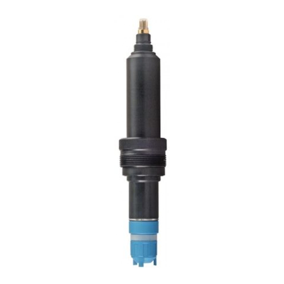
CCS120 Operation Operation Sensor design a0006354 Fig. 7: Sensor design Membrane cap Thread NPT 3/4" Sensor shaft TOP68 plug Measuring principle The amperometric sensor is based on the conversion of the measuring variable chlorine in electrical current. Two electrodes covered by an electrolyte are in contact to the medium via a membrane. -
Page 14: Electrolyte Fill In
Operation CCS120 Electrolyte fill in Warning! Do not swallow the electrolyte. Avoid contact of the electrolyte with skin and eyes. Otherwise wash with a lot of water. In case of eye inflamation, contact a doctor. " Caution! • Do not touch or damage the membrane or electrodes. - Page 15 CCS120 Operation Perform the following steps to fill the membrane cap with electrolyte: Open the electrolyte bottle and screw on the nozzle. Squeeze out excess air. Place the electrolyte bottle completely onto the membrane cap (Fig. 8). Slowly squeeze the electrolyte out of the bottle in one steady stream, while continously retracting the bottle.
-
Page 16: Commissioning
Commissioning CCS120 Commissioning Note! • Read also the instructions for operation and commissioning in the operating instructions of the transmitter. • The power supply to the transmitter and to the sensor must not be interrupted. If the power supply is interrupted (> 2 hours) the sensor must be re-commissioned (polarisation time). - Page 17 CCS120 Commissioning Requirements The sensor reading is stable (no drifts or unsteady values for at least 5 minutes). This is normally fulfilled, when: • The polarisation period is finished. • The flow is constant and within the correct range. • The sample medium and the sensor are at the same temperature.
-
Page 18: Maintenance
Maintenance CCS120 Maintenance Note! • Service the sensor regularly to avoid incorrect dosing within a control system, due to incorrect measured value. • Do not touch the electrodes or allow them to come into contact with greasy substances. • Never attempt to clean the membrane with acid/alkaline solutions, cleaning reagents or mechanical aids (brushes or similar). -
Page 19: Accessories
• Order numbers: – cable entry Pg 13.5: 50003987 – cable entry NPT ½": 51500177 • Measuring cable CCS120-1M, cable length: 1 m (3.28 ft), for compact chlorine system CCE1 order no. 51517204 • Special measuring cable CPK9-N*A1B internal PM wire... -
Page 20: Maintenance/Calibration
Chlorine measuring range: 0.05 to 6 mg/l pH measuring range: 6.5 to 8.4 • Electrolyte for CCS120, 50 ml order no. 51516343 • Service kit for CCS120, consists of 2 membrane caps and 1 bottle of electrolyte (50 ml) order no. 51517284 Troubleshooting Troubleshooting instructions Troubleshooting must take account of the whole measuring system. - Page 21 CCS120 Troubleshooting Fault Possible cause Action Sensor cannot be calibrated. Polarisation time not finished Wait until polarisation time is finished Measured value higher than Membrane cap is damaged Replace membrane cap; wait until DPD measurement polarisation time is finished, calibrate...
-
Page 22: Return
Troubleshooting CCS120 Fault Possible cause Action Measured value of sensor is Chlorine concentration exceeds the Check the whole system, remedy fault and arbitrary and sensor current upper limit of measuring range calibrate sensor > 5 µA Distance between electrode and... -
Page 23: Technical Data
CCS120 Technical data Technical data 10.1 Input Measured variable Total chlorine Free chlorine (Cl (dissolved), HOCl, OCl Bound chlorine (chloramines) Organic-bound chlorine (e.g. cyanuric acid derivates) Applications Drinking, industrial, process, cooling water, fresh water and sea water for swimming pool and whirlpool treatment Measuring range 0.1 ... -
Page 24: Power Supply
Technical data CCS120 10.4 Power supply Power supply 15 V DC, 10 mA 10.5 Environment Storage temperature Filled with electrolyte: 5 ... 50 °C (41 ... 122 °F) Without electrolyte: -20 ... +60 °C (-4 ... +140 °F) Ingress protection IP 65 10.6 Mechanical construction... -
Page 25: Index
CCS120 Index Accessories Maintenance ......18 Assemblies ......19 Materials. - Page 26 CCS120...
- Page 27 Declaration of contamination Dear customer, Because of legal determinations and for the safety of our employees and operating equipment, we need this "Declaration of contamination" with your signature before your order can be handled. Please, include the completely filled in declaration with the device and the shipping documents in any case. Add also safety sheets and / or specific handling instructions if necessary.
- Page 28 www.endress.com/worldwide BA388C/07/en/07.06 Printed in Germany / FM+SGML 6.0 / 51517372...
Need help?
Do you have a question about the CCS120 and is the answer not in the manual?
Questions and answers