
Subscribe to Our Youtube Channel
Related Manuals for Endress+Hauser CCS240


Summary of Contents for Endress+Hauser CCS240
- Page 1 Products Solutions Services BA00114C/07/EN/14.18 71423118 2018-10-23 Operating Instructions CCS240/241 Sensors for measuring chlorine dioxide...
-
Page 3: Table Of Contents
CCS240/241 Table of contents Table of contents About this document ... 4 Accessories ....31 Warnings . -
Page 4: About This Document
About this document CCS240/241 About this document Warnings Structure of information Meaning This symbol alerts you to a dangerous situation. DANGER Failure to avoid the dangerous situation will result in a fatal or serious injury. Causes (/consequences) If necessary, Consequences of non- compliance (if applicable) ‣... - Page 5 CCS240/241 About this document 1.2.1 Symbols on the device Symbol Meaning Reference to device documentation Endress+Hauser...
-
Page 6: Basic Safety Instructions
Basic safety instructions CCS240/241 Basic safety instructions Requirements for the personnel Installation, commissioning, operation and maintenance of the measuring system may be carried out only by specially trained technical personnel. ‣ The technical personnel must be authorized by the plant operator to carry out the specified activities. -
Page 7: Product Safety
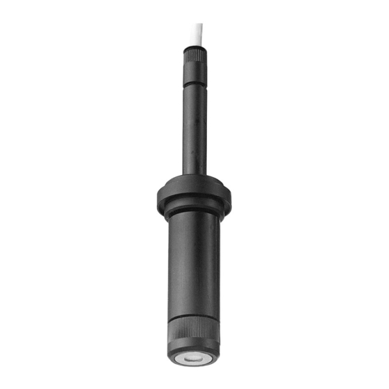
CCS240/241 Product description Ensure that electrical cables and hose connections are undamaged. Do not operate damaged products, and protect them against unintentional operation. Label damaged products as defective. During operation: ‣ If faults cannot be rectified: products must be taken out of service and protected against unintentional operation. - Page 8 Product description CCS240/241 Fixed cable Sensor shaft O-ring Large anode, silver/silver chloride Gold cathode Measuring chamber Membrane cap with dirt-repellent membrane Screw cap for securing the membrane cap A0037109 3.1.1 Measuring principle Chlorine dioxide levels are determined in accordance with the amperometric measuring principle.
- Page 9 CCS240/241 Product description The installation of an INS proximity switch in the assembly enables reliable detection of this invalid operating status, thus triggering an alarm or causing the dosing process to be switched off if necessary. Below the minimum flow rate, the sensor current is more sensitive to flow fluctuations. For abrasive media, it is recommended not to exceed the minimum flow.
-
Page 10: Incoming Acceptance And Product Identification
Incoming acceptance and product identification CCS240/241 Incoming acceptance and product identification Incoming acceptance Verify that the packaging is undamaged. Notify the supplier of any damage to the packaging. Keep the damaged packaging until the issue has been resolved. Verify that the contents are undamaged. - Page 11 A new window (Device Viewer) opens. All of the information relating to your device is displayed in this window as well as the product documentation. 4.2.4 Manufacturer address Endress+Hauser Conducta GmbH+Co. KG Dieselstraße 24 D-70839 Gerlingen 4.2.5 Scope of delivery The delivery comprises: •...
-
Page 12: Installation
Installation CCS240/241 Installation Installation conditions 5.1.1 Installation position 5.1.2 Dimensions Ø12 (0.47) Ø 36 (1.42) Ø 29 (1.14) Ø 25 (0.98) A0037111 1 Dimensions in mm (in) Version with TOP68 plug-in head Version with fixed cable connection Endress+Hauser... -
Page 13: Mounting The Sensor
REL 2 A0037976 2 Example of a measuring system Flowfit CCA250 flow assembly Inlet to Flowfit CCA250 flow assembly Proximity switch (optional) PML pin Chlorine dioxide sensor l CCS240 Procedure Sampling tap Measuring cable CPK9 Liquisys CCM223/253 transmitter Endress+Hauser... - Page 14 Installation CCS240/241 ‣ Ground the medium at the sensor by means of the PML pin to ensure a high reading stability. 5.2.2 Preparing the sensor Removing protection cap from sensor NOTICE Negative pressure causes damage to the sensor's membrane cap.
-
Page 15: Post-Installation Check
CCS240/241 Electrical connection 5.2.3 Installing sensor in assembly CCA250 The Flowfit CCA250 flow assembly is designed for installing the sensor. It allows a pH and ORP sensor to be installed, in addition to the chlorine or chlorine dioxide sensor. A needle valve controls the flow rate in the range of 30 to 120 l/h (7.9 to 31.7 gal/h). -
Page 16: Connecting The Sensor
Electrical connection CCS240/241 Connecting the sensor ‣ Install the grounding bar (order number 51501086) in accordance with the accompanying instructions in order to guarantee a high reading stability. NOTICE Measured errors due to faulty connection ‣ When connecting the sensor cable, make sure that the black semi-conductor layer is removed as far as the inner shield. - Page 17 CCS240/241 Electrical connection A0037112 6 Sensor with TOP68 plug-in head and CPK9 measuring cable with internal PAL (CPK9-N*A1B) Signal (cathode) (black coax) Reference (anode) (screened coax) Not used (white) Temperature sensor (green) Temperature sensor (yellow) Not used (brown) 6.1.1 Connecting the cable extension To extend the sensor connection, use the VBC junction box.
-
Page 18: Ensuring The Degree Of Protection
Electrical connection CCS240/241 7.2 (0.28) ±0.1 A0037106 8 Structure of measuring cable CYK71, specifications in mm (in) Coax, e.g. pH, ORP Shielding 4 control lines YE/GN/WH/BN Ensuring the degree of protection Only the mechanical and electrical connections which are described in these instructions and which are necessary for the required, designated use, may be carried out on the device delivered. -
Page 19: Commissioning
CCS240/241 Commissioning Commissioning Function check Prior to initial commissioning, ensure that: • The sensor is correctly installed • The electrical connection is correct. • There is sufficient electrolyte in the membrane cap and the transmitter is not displaying a warning about electrolyte depletion. - Page 20 Commissioning CCS240/241 Requirements The sensor reading is stable (no drifts or unsteady values for at least 5 minutes), and the medium is stable. This is normally guaranteed once the following preconditions have been met: • The polarization period has elapsed.
-
Page 21: Diagnostics And Troubleshooting
CCS240/241 Diagnostics and troubleshooting Diagnostics and troubleshooting When troubleshooting, you must take account of the entire measuring system. This comprises: • Transmitter • Electrical connections and lines • Assembly • Sensor The possible causes of error in the following table refer primarily to the sensor. Before commencing troubleshooting, ensure that the following operating conditions have been met: •... - Page 22 Diagnostics and troubleshooting CCS240/241 Error Possible cause Remedy ‣ Display value too low Measuring chamber not Fully tighten measuring chamber or screw cap completely tightened ‣ Membrane soiled Clean membrane ‣ Air bubble in front of membrane Release air bubble ‣...
-
Page 23: Maintenance
CCS240/241 Maintenance Maintenance Please note the information on the safety data sheet to ensure safe use of the electrolyte. Take all the necessary precautions in time to ensure the operational safety and reliability of the entire measuring system. NOTICE Effects on process and process control! ‣... - Page 24 Maintenance CCS240/241 9.2.2 Replacing the membrane A0037110 9 Replacing the membrane Measuring chamber Membrane cap Screw cap Unscrew the measuring chamber (1). Unscrew the front screw cap (3). Remove the membrane cap (2) and replace it with a CCY14-WP replacement cartridge.
- Page 25 CCS240/241 Maintenance 9.2.3 Refilling the electrolyte NOTICE Damage to membrane and electrodes, air bubbles Possibility of measured errors to complete failure of the measuring point ‣ Do not touch the membrane or electrodes. Avoid damaging them. ‣ The electrolyte is chemically neutral and is not hazardous to health. Nonetheless, do not swallow it and avoid contact with eyes.
- Page 26 Maintenance CCS240/241 For recommissioning, follow the same procedure as for commissioning → 19. Ensure that no biofouling occurs during longer interruptions to measurement. Remove continuous organic deposits such as films of bacteria. Fit protection cap on sensor. To keep the membrane moist after the sensor has been removed, refill the protection cap with electrolyte or clean water.
- Page 27 CCS240/241 Maintenance 9.2.5 Regenerating the sensor During measurement, the electrolyte in the sensor is gradually exhausted due to chemical reactions. The gray-brown silver chloride layer that is applied to the anode at the factory continues to grow during sensor operation. However, this has no effect on the reaction taking place at the cathode.
- Page 28 Maintenance CCS240/241 A0037414 Sensor Gas phase of aqueous chlorine dioxide solution Aqueous chlorine dioxide solution Distance between sensor and liquid, 5 to 10 mm (0.2 to 0.4 in) Close the medium inlet and outlet and make sure that no medium can escape from the assembly.
- Page 29 CCS240/241 Maintenance When the sensor current has reached a value of several hundred nA: Leave the sensor in this position for approx. 20 minutes. If the value of several hundred nA is not reached: Cover the beaker to avoid a rapid exchange of air.
-
Page 30: Repair
The product must be returned if repairs or a factory calibration are required, or if the wrong product was ordered or delivered. As an ISO-certified company and also due to legal regulations, Endress+Hauser is obliged to follow certain procedures when handling any returned products that have been in contact with medium. -
Page 31: Accessories
• Terminated measuring cable for connecting analog sensors with TOP68 plug-in head • Selection in accordance with product structure • Ordering information: Endress+Hauser sales office or www.endress.com. MK extension cable • Twin-core signal cable with additional shielding and PVC insulation •... -
Page 32: Technical Data
• Product Configurator on the product page: www.endress.com/coy8 Technical Information TI01244C Service kit CCS24x • For chlorine dioxide sensors CCS240 / CCS241 • 2 replacement cartridges, electrolyte 50 ml (1.69 fl.oz), sanding sheets • Order No. 71076922 Polishing sheet COY31-PF •... -
Page 33: Performance Characteristics
IP68 IP (up to mounting collar Ø 36 mm (1.42")) 12.4 Process 12.4.1 Process temperature CCS240, CCS241 2 to 45 °C (36 to 113 °F) 12.4.2 Process pressure max. 1 bar (14.5 psi) absolute, if installed in the Flowfit CCA250 assembly... -
Page 34: Mechanical Construction
Technical data CCS240/241 12.4.3 pH range in stability range of ClO (typical application: pH 4 to 10) Chlorine measurement possible up to pH 9 with limited accuracy 12.4.4 Flow At least 30 l/h (7.9 gal/h), in the CCA250 assembly 12.4.5 Minimum flow At least 15 cm/s (0.5 ft/s) -
Page 35: Index
CCS240/241 Index Index Installation position ....12 Accessories ..... 31 Ambient temperature range . - Page 36 Index CCS240/241 Connecting ....16 Mounting ....13 Polarization .
- Page 40 *71423118* 71423118 www.addresses.endress.com...
Need help?
Do you have a question about the CCS240 and is the answer not in the manual?
Questions and answers