
Related Manuals for Endress+Hauser Oxymax COS61


Summary of Contents for Endress+Hauser Oxymax COS61
-
Page 1: Operating Instructions
Operating Instructions Oxymax COS61 Dissolved oxygen sensor BA00387C/07/EN/13.12 71162645... -
Page 2: Symbols Used
This symbol indicates a cross reference to a defined page (e.g. p. 1). È å 2 This symbol indicates a cross reference to a defined figure (e.g. fig. 2). Additional information, tips Permitted or recommended Forbidden or not recommended Endress+Hauser... - Page 3 Oxymax COS61 Table of contents Basic safety instructions ... . 4 Technical data ....28 Requirements for personnel .
-
Page 4: Designated Use
Basic safety instructions Oxymax COS61 Basic safety instructions Requirements for personnel ► Installation, commissioning, operation and maintenance of the measuring system must only be carried out by trained technical personnel. ► The technical personnel must be authorized by the plant operator to carry out the specified activities. -
Page 5: Product Safety
Oxymax COS61 Basic safety instructions Product safety The product is designed to meet state-of-the-art safety requirements, has been tested and left the factory in a condition in which it is safe to operate. Relevant regulations and European standards have been observed. -
Page 6: Scope Of Delivery
Identification Oxymax COS61 Identification Product page and configurator You can create a complete and valid order code by using the configurator on the internet product page. Product page link: www.products.endress.com/cos61 Order code You can choose from the following options on the product page located on the right: Click "Configure this product". -
Page 7: Installation
Oxymax COS61 Installation Installation Incoming acceptance, transport, storage ► Make sure the packaging is undamaged! ► Inform the supplier about any damage to the packaging. Keep the damaged packaging until the matter has been settled. ► Make sure the contents are undamaged! ►... -
Page 8: Installation Instructions
• Select an installation location which produces a typical oxygen concentration. Installation instructions 3.3.1 Measuring system A complete measuring system comprises: • Oxygen sensor Oxymax COS61 • Transmitter, e.g. Liquisys COM2x3-W • Special measuring cable • Assembly, e.g. COA250 flow assembly, CYA112 immersion assembly or COA451 retractable assembly Optional: •... - Page 9 Oxymax COS61 Installation a0012885 Fig. 4: Measuring system (example) Liquisys COM253 transmitter Medium flow direction COS61 oxygen sensor Retractable assembly Cleanfit COA451 Pipework (ascending pipe) Sensor cable 3.3.2 Installing a measuring point For immersed operation, install the individual modules away from the basin on a solid base.
-
Page 10: Installation Examples
Installation Oxymax COS61 Installation examples 3.4.1 Immersion operation Upright post and chain assembly For large basins, where sufficient installation distance is required from the basin edge (aeration basin, especially), it is advisable to use the upright post and chain assembly. The free swinging of the immersed assembly practically rules out vibrations from the upright post. - Page 11 Oxymax COS61 Installation Upright post and fixed immersion assembly The preferable type of installation for strong or turbulent flow (> 0.5 m/s) in the basin or open channels is to secure the device to an upright post and a securely mounted immersion tube. If the flow is very strong, a second transverse pipe can be installed with its own pipe support.
- Page 12 Installation Oxymax COS61 Basin rim mounting with immersion assembly For fixing to the sides of the basin or channel, we recommend the pendulum holder of the immersion tube. Optionally, you can also use the assembly with a float. a0013693 Fig. 8:...
- Page 13 Oxymax COS61 Installation 3.4.2 Flow assembly The COA250 flow assembly with automatic self-venting is suitable for use in pipelines or hose connections. The inlet is at the bottom of the assembly, the outlet at the top (connection thread G¾). It can be installed in a pipe by using two 90˚ pipe brackets to allow inflow to the assembly (→...
-
Page 14: Post-Installation Check
Installation Oxymax COS61 NOTICE Sensor not immersed into the medium, suspended particles settled on the sensor membrane or sensor optics, sensor installed overhead Measuring errors can occur ► Do not install the assembly at places, where air cushions or foam bubbles can be formed or where suspended particles can settle on the sensor membrane or optics (→... -
Page 15: Wiring
Oxymax COS61 Wiring Wiring WARNING Device is energized Improper connection can cause injury or death. ► The electrical connection must only be carried out by a certified electrician. ► Technical personnel must have read and understood the instructions in this manual and must adhere to them. -
Page 16: Connection Via Junction Box
Wiring Oxymax COS61 Connection via junction box To lengthen the sensor connection beyond the length of the fixed cable, you require a junction box Always connect the sensor cable with the SXP plug to the junction box. The cable extension to the transmitter then depends from the transmitter version, i.e. field device or panel mounted device. -
Page 17: Device Description
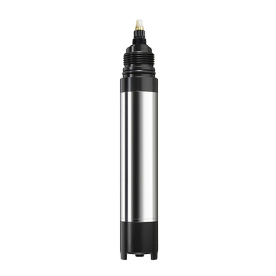
Oxymax COS61 Device description Device description Sensor design a0004151 Fig. 16: Sensor design Sensor cable Sensor shaft O-ring Protection guard Threaded connection Detector Emitter diode Fluorescence cap The sensor consists of the following function units: • Sensor shaft • Sensor head with optics (emitter and detector) •... -
Page 18: Measuring Principle
Device description Oxymax COS61 Measuring principle 5.2.1 Oxygen measurement based on the principle of fluorescence quenching • Sensor design: – Oxygen-sensitive molecules (markers) are integrated in an optically active layer (fluorescence layer). – The surface of the fluorescence layer is in contact with the medium. - Page 19 Oxymax COS61 Device description 5.3.1 Types of calibration Types of calibration: • Air (preferably saturated water vapor, e.g. near the water surface) – Measured values between 70 and 130 %SAT result in the calibration of the measured value at – Measured values smaller than 15 %SAT result in the calibration of the zero point •...
- Page 20 Device description Oxymax COS61 ˚ C / ˚F S [mg/ ˚ C / ˚F S [mg/ ˚ C / ˚F S [mg/ ˚ C / ˚F S [mg/ l=ppm] l=ppm] l=ppm] l=ppm] 0 / 32 14.64 11 / 52 10.99 21 / 70 8.90...
-
Page 21: Commissioning
Oxymax COS61 Commissioning Commissioning Function check Before first commissioning, check if: • the sensor is correctly installed • the electrical connection is correct. If using an assembly with automatic cleaning, check the correct connection of the cleaning agent (e.g. water or air). -
Page 22: Maintenance
Maintenance Oxymax COS61 Maintenance Maintenance work must carried out at regular intervals. To ensure that it is carried out, we recommend you enter the maintenance dates into an operations logbook or in an operations calendar in advance. The maintenance cycle primarily depends on: •... -
Page 23: Replacing Wear And Tear Materials
Oxymax COS61 Maintenance 7.1.2 Cleaning the optics The optics only need to be cleaned if medium has penetrated through a defective fluorescence cap. To clean it, proceed as follows: Unscrew the protection guard and fluorescence cap from the sensor head. -
Page 24: Accessories
Accessories Oxymax COS61 Accessories In the following sections, you find the accessories available at the time of issue of this documentation. For information on accessories that are not listed here, please contact your local service or sales center. Connection accessories VS junction box •... -
Page 25: Cleaning And Calibration
Oxymax COS61 Accessories Baffle plate OP • extra protection for extreme flow conditions • order no. 50028712 Membrane protection guard COY3-SK • for sensor use in fish ponds • order no. 50081787 Cleaning and calibration Pressurized air cleaning system for COSXX •... -
Page 26: Trouble-Shooting
Trouble-shooting Oxymax COS61 Trouble-shooting Trouble-shooting instructions Problem Check Remedial action Mains voltage to the transmitter? Connect mains voltage. Sensor connected correctly? Set up correct connection. No display, no sensor reaction Coating on the fluorescence cap? Clean the sensor. Medium flow available? Create flow. -
Page 27: Spare Parts
The device must be returned if repairs or a factory calibration are required, or if the wrong device has been ordered or delivered. According to legal regulations, Endress+Hauser, as an ISO-certified company, is required to follow certain procedures when handling returned products that are in contact with medium. -
Page 28: Technical Data
Technical data Oxymax COS61 Technical data 10.1 Input Measured variable Dissolved oxygen [mg/l, % SAT, hPa] Temperature [˚ C, ˚ F] Measuring range With Liquisys COM 2x3-W: 0 to 20 mg/l (0 to 20 ppm) 0 to 200 % SAT 0 to 400 hPa 10.2... -
Page 29: Mechanical Construction
Oxymax COS61 Technical data 10.5 Mechanical construction Weight With cable length 7 m (23 ft): 0.7 kg (1.5 lbs.) With cable length 15 m (49 ft): 1.1 kg (2.4 lbs.) With TOP68 plug-in connection: 0.3 kg (0.66 lbs.) Materials Sensor shaft: stainless steel 1.4571 (AISI 316Ti) -
Page 30: Index
Oxymax COS61 Index Accessories Immersion assembly ......24 Assemblies ....... . . 24 Immersion operation. - Page 31 Oxymax COS61 Scope of delivery ....... . . 6 Sealing ring ........23 Sensor Checks .
- Page 32 BA00387C/07/EN/13.12 FM10...
Need help?
Do you have a question about the Oxymax COS61 and is the answer not in the manual?
Questions and answers