Endress+Hauser Turbimax CUS71D Operating Instructions Manual
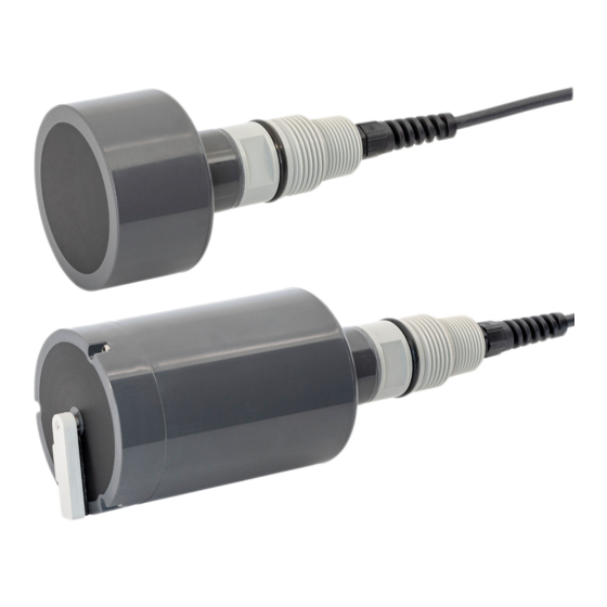
Ultrasonic interface sensor
Hide thumbs
Also See for Turbimax CUS71D:
- Operating instructions manual (32 pages) ,
- Operating instructions manual (32 pages)

Related Manuals for Endress+Hauser Turbimax CUS71D


Summary of Contents for Endress+Hauser Turbimax CUS71D
- Page 1 Products Solutions Services BA00490C/07/EN/06.18 71415440 2018-05-01 Operating Instructions Turbimax CUS71D Ultrasonic interface sensor...
-
Page 3: Table Of Contents
Turbimax CUS71D Table of contents Table of contents About this document ... 4 Repairs ......23 Warnings . -
Page 4: About This Document
About this document Turbimax CUS71D About this document Warnings Structure of information Meaning This symbol alerts you to a dangerous situation. DANGER Failure to avoid the dangerous situation will result in a fatal or serious injury. Causes (/consequences) If necessary, Consequences of non- compliance (if applicable) ‣... -
Page 5: Basic Safety Instructions
Turbimax CUS71D Basic safety instructions 1.2.1 Symbols on the device Symbol Meaning Reference to device documentation Basic safety instructions Requirements for personnel • Installation, commissioning, operation and maintenance of the measuring system may be carried out only by specially trained technical personnel. -
Page 6: Workplace Safety
Basic safety instructions Turbimax CUS71D Workplace safety As the user, you are responsible for complying with the following safety conditions: • Installation guidelines • Local standards and regulations Electromagnetic compatibility • The product has been tested for electromagnetic compatibility in accordance with the applicable European standards for industrial applications. -
Page 7: Operational Safety
Turbimax CUS71D Basic safety instructions Operational safety Before commissioning the entire measuring point: Verify that all connections are correct. Ensure that electrical cables and hose connections are undamaged. Do not operate damaged products, and protect them against unintentional operation. Label damaged products as defective. -
Page 8: Product Description
Product description Turbimax CUS71D Product description Product design The sensor is designed for continuous in-situ determination of interfaces. The sensor includes all necessary modules: • Power supply • The ultrasonic source emits the measurement signals. • The ultrasonic receiver receives the measurement signals, digitalizes the signals and converts them to a measurement value. -
Page 9: Product Identification
Endress+Hauser Conducta GmbH+Co. KG Dieselstraße 24 D-70839 Gerlingen Scope of delivery The delivery comprises: • 1 Turbimax CUS71D sensor, version as ordered • 1 set of Operating Instructions BA00490C/07/EN ‣ If you have any queries: Please contact your supplier or local sales center. -
Page 10: Certificates And Approvals
Incoming acceptance and product identification Turbimax CUS71D Certificates and approvals 4.4.1 mark The product meets the requirements of the harmonized European standards. As such, it complies with the legal specifications of the EU directives. The manufacturer confirms successful testing of the product by affixing to it the mark. -
Page 11: Installation
Turbimax CUS71D Installation Installation Installation conditions 5.1.1 Installation instructions Basin configuration 6° A0031574 1 Basin configuration Sensor 50 cm (1.64 ft) Minimum distance between sensor and basin rim Fixed reference point, e.g. surface of water, basin rim, bridge/walkway etc. - Page 12 Installation Turbimax CUS71D Mount the sensor so that it is straight and parallel to the basin wall (measured value offset). Do not install the sensor in zones where air bubbles, turbulence, high concentrations of turbid material and suspended matter, or foam formation occur (e.g.
- Page 13 Turbimax CUS71D Installation Circular clarifier ¹/₃ ²/₃ ¹/₃ ²/₃ A0031579 4 Basin configuration in circular clarifiers View from above Cross-section Surface skimmer Sensor Bridge/walkway Rail Sensor position range Surface skimmer Floor rake Floor rake Direction of rake movement Endress+Hauser...
-
Page 14: Mounting The Sensor
Mounting the sensor 5.2.1 Measuring system A complete measuring system comprises: • Turbimax CUS71D ultrasonic sensor • Liquiline CM44x multi-channel transmitter and is optionally delivered with the following accessories: • A weather protection cover CYY101 • A Flexdip CYH112 holder •... - Page 15 Turbimax CUS71D Installation 90° A0031577 5 Ultrasonic sensor with basin holder system and multi-channel transmitter Flexdip CYH112 holder Liquiline CM44x multi-channel transmitter Protective cover Flexdip CYA112 assembly Turbimax CUS71D ultrasonic sensor Vertical from all sides Splash protection cap Endress+Hauser...
- Page 16 Installation Turbimax CUS71D 5.2.2 Measuring system with pendulum holder A0031578 6 Measuring system with pendulum holder Flexdip CYH112 holder (cross clamp) Flexdip CYH112 holder (pendulum holder) Flexdip CYA112 assembly with CUS71D PVC sensor protector Splash protection cap The PVC sensor protector protects the ultrasonic sensor from being damaged by the surface skimmer.
-
Page 17: Post-Installation Check
Turbimax CUS71D Electrical connection Post-installation check Check the following: • Are the sensor and cable undamaged? • Is the cap undamaged? • Is the orientation correct? • Is the sensor installed in an assembly and not suspended from the cable? Avoid the penetration of moisture by fitting the protective cap on the assembly. - Page 18 Electrical connection Turbimax CUS71D Connect the fixed cable of the sensor to the Liquiline CM44x transmitter as follows: Sensor A0034802 7 Sensor connection The maximum cable length is 100 m (328 ft). Use the following accessories to extend the sensor cable if necessary: •...
- Page 19 Turbimax CUS71D Electrical connection Cable sample (does not necessarily correspond to the original cable supplied) 8 Terminated cable 9 Insert the cable 10 Tighten screw (2 Nm) Outer shield (exposed) Grounding clip The cable shield is grounded by the Cable cores with ferrules grounding clip.
-
Page 20: Post-Connection Check
Commissioning Turbimax CUS71D Post-connection check Device condition and specifications Notes Are the sensor, assembly, or cables free from damage on the outside? Visual inspection Electrical connection Notes Are the mounted cables strain-relieved and not twisted? Is a sufficient length of the cable cores stripped, and are the cores... -
Page 21: Cyclic Cleaning
Turbimax CUS71D Diagnostics and troubleshooting Cyclic cleaning Cyclic cleaning is available for ultrasonic sensors with an integrated wiper. The wiper interval is set to 240 minutes at the factory. Automatic wiper function Sensor versions with a wiper have an integrated automatic wiper function. The wiper starts as soon as the sensor stops receiving a signal. -
Page 22: Maintenance
Maintenance Turbimax CUS71D Maintenance ‣ You must perform maintenance tasks at regular intervals. We recommend setting the maintenance times in advance in an operations journal or log. The maintenance cycle primarily depends on the following: • The system • The installation conditions •... -
Page 23: Repairs
The product must be returned if repairs or a factory calibration are required, or if the wrong product was ordered or delivered. As an ISO-certified company and also due to legal regulations, Endress+Hauser is obliged to follow certain procedures when handling any returned products that have been in contact with medium. -
Page 24: Disposal
Repairs Turbimax CUS71D 11.4 Disposal The device contains electronic components. and must therefore be disposed of in accordance with regulations on the disposal of electronic waste. ‣ Observe the local regulations. Endress+Hauser... -
Page 25: Accessories
Turbimax CUS71D Accessories Accessories The following are the most important accessories available at the time this documentation was issued. ‣ For accessories not listed here, please contact your Service or Sales Center. 12.1 Assemblies FlexdipCYA112 • Immersion assembly for water and wastewater •... -
Page 26: Holder
Accessories Turbimax CUS71D Ø 41 (1.6) Ø 50 (2.0) Ø 76 (3) Ø 99 (3.9) A0037314 11 PVC sensor protector for CUS71D. Dimensions: mm (in) CYA112 assembly PVC sensor protector CUS71D ultrasonic sensor 12.2 Holder Flexdip CYH112 • Modular holder system for sensors and assemblies in open basins, channels and tanks •... -
Page 27: Cable Extension
Turbimax CUS71D Technical data 12.3 Cable extension Memosens data cable CYK11 • Extension cable for digital sensors with Memosens protocol • Product Configurator on the product page: www.endress.com/cyk11 Technical Information TI00118C Junction box, cable/cable • Material: aluminum, painted • Cable extension: Memosens sensors, Liquiline •... -
Page 28: Environment
Technical data Turbimax CUS71D 13.3 Environment 13.3.1 Storage temperature –20 to 50 °C (–4 to 120 °F) 13.3.2 Degree of protection IP 68 (1 m (3.3 ft) water column over 60 days, 1 mol/l KCl) 13.4 Process 13.4.1 Process temperature 1 to 50 °C (34 to 122 °F) -
Page 29: Index
Turbimax CUS71D Index Index Product description ....8 Product design ....8 Accessories . - Page 32 *71415440* 71415440 www.addresses.endress.com...
Need help?
Do you have a question about the Turbimax CUS71D and is the answer not in the manual?
Questions and answers