Endress+Hauser Turbimax CUS51D Operating Instructions Manual
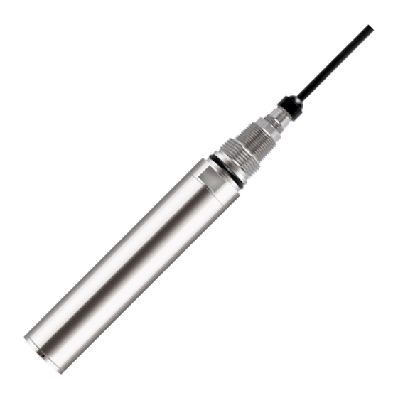
Sensor for turbidity and solids content
Hide thumbs
Also See for Turbimax CUS51D:
- Operating instructions manual (48 pages) ,
- Technical information (17 pages) ,
- Operating instructions manual (41 pages)

Subscribe to Our Youtube Channel
Related Manuals for Endress+Hauser Turbimax CUS51D


Summary of Contents for Endress+Hauser Turbimax CUS51D
- Page 1 Operating Instructions Turbimax CUS51D Sensor for turbidity and solids content BA00461C/07/EN/14.12 71141799...
- Page 2 Endress+Hauser...
-
Page 3: Table Of Contents
Turbimax CUS51D Table of contents Safety instructions ....4 Technical Data....28 Designated use . -
Page 4: Safety Instructions
Safety instructions Turbimax CUS51D Safety instructions Designated use CUS51D is a sensor designed to measure the turbidity and solids content of water and wastewater. The sensor is particularly suited for use in the following applications: • Turbidity measurement in the outlet •... -
Page 5: Notes On Safety Icons And Symbols
Turbimax CUS51D Safety instructions Notes on safety icons and symbols The structure, signal words and safety colors of the signs comply with the specifications of ANSI Z535.6 ("Product safety information in product manuals, instructions and other collateral materials"). Safety message structure Meaning This symbol alerts you to a dangerous situation. -
Page 6: Identification
Scope of delivery The scope of delivery comprises: • 1 sensor Turbimax CUS51D in the ordered version • 1 Operating Instructions BA461C/07/en If you have any questions, please contact your supplier or your local sales center. Certificates and approvals Declaration of conformity The product meets the requirements of the harmonized European standards. -
Page 7: Installation
Turbimax CUS51D Installation Installation Incoming acceptance, transport, storage • Make sure the packaging is undamaged! • Inform the supplier about any damage to the packaging. Keep the damaged packaging until the matter has been settled. • Make sure the contents are undamaged! •... -
Page 8: Installation Instructions
Turbimax CUS51D Installation instructions 3.3.1 Measuring system A complete measuring system comprises: • Turbidity sensor Turbimax CUS51D • Transmitter Liquiline • Assembly: – Assembly Flexdip CYA112 and holder system Flexdip CYH112 or – Retractable assembly , e.g. Cleanfit CUA451 a0012965 Fig. - Page 9 Installation a0013334 Abb. 3: Measuring system with immersion assembly (example) Transmitter Liquiline Assembly Flexdip CYA112 Weather protection roof Turbidity sensor Turbimax CUS51D Holder system Flexdip CYH112 a0012964 Fig. 4: Measuring system with retractable assembly (example) Turbidity sensor Turbimax CUS51D Transmitter Liquiline...
-
Page 10: Installation Examples
Fixed installation with wastewater assembly a0013383 a0012965 Abb. 5: Installation secured on railing Abb. 6: Installation with upright post Turbidity sensor Turbimax CUS51D Flexdip CYH112 holder Flexdip CYA112 wastewater assembly Multichannel transmitter Liquiline CM44x Flexdip CYH112 holder Weather protection cover Railing... - Page 11 Fig. 7: Chain retainer on railing Fig. 8: Chain retainer on upright post Flexdip CYA112 wastewater assembly with Flexdip CYH112 holder Turbimax CUS51D turbidity sensor Multichannel transmitter Liquiline CM44x Chain Weather protection cover Flexdip CYH112 holder Flexdip CYA112 wastewater assembly...
- Page 12 Turbimax CUS51D Cleaning unit a0013259 Fig. 9: Turbimax CUS51D sensor with cleaning unit The cleaning unit is particularly suitable for clear water and media containing fats/oils that tend to cause heavy buildup. Mount the cleaning unit as follows: Fit the cleaning unit onto the sensor as far as it will go.
- Page 13 Turbimax CUS51D Installation 3.4.2 Pipe installation Arrow 1 shows the flow direction. The installation angle α must not exceed 90°. The recommended installation angle is 75°. The optical windows of the sensor have to be aligned parallel to the flow direction (α = 90°) or face the flow direction (α...
-
Page 14: Post-Installation Check
Installation Turbimax CUS51D The following figure illustrates various installation positions in pipes and indicates whether they are permitted or not. a0013011 Fig. 14: Orientation and installation positions (with retractable assembly CUA451) • The pipeline diameter must be at least 100 mm (4") if reflective materials (e.g. stainless steel) are used. -
Page 15: Wiring
Turbimax CUS51D Wiring Wiring WARNING Device is energized Improper connection can cause injury or death. • The electrical connection must only be carried out by a certified electrician. • Technical personnel must have read and understood the instructions in this manual and must adhere to them. -
Page 16: Device Description
Device description Turbimax CUS51D Device description Sensor design The sensor is designed for the continuous in-situ measurement of turbidity and solids content. The sensor is designed as a 40 mm sensor that can be operated directly and completely in the process without the need for further sampling (in situ). - Page 17 Turbimax CUS51D Device description 135° 90° a0012986 Fig. 17: Principle operating mode of the turbidity sensor Light source 135° light receiver 90° light receiver If only a small number of particles is in the medium, most of the light will be scattered to the 90°...
- Page 18 Device description Turbimax CUS51D The turbidity sensor CUS51D is equipped with two independing sensor units that are arranged in parallel. The application-specific analysis of both signals results in stable measured values. a0012966 Fig. 19: Arrangement of the light souces and the light receivers Light sources 1 and 2 135°...
-
Page 19: Measuring Methods
Turbimax CUS51D Device description Measuring methods Four-beam pulsed light method The method is based on two light sources and four light receivers. Long-life LEDs are used as monochromatic light sources. To eliminate interference from extraneous light sources, these LEDs are pulsed. - Page 20 Device description Turbimax CUS51D 135° backscattered light method The transmitted light beam is scattered by the solid matter particles in the medium. The backscattered beams are detected by scattered light receivers, which are arranged next to the light sources. The turbidity of the medium is determined by the amount of backscattered light.
-
Page 21: Calibration
Turbimax CUS51D Device description Calibration CAUTION Risk of injury caused by acid or medium • Switch off the cleaning unit before removing the sensor from the medium. The sensor enables measurement in a variety of ways that are adapted to suit the specific measurement problems. - Page 22 Device description Turbimax CUS51D 5.4.2 Stability criterion During the calibration process, the measured values returned by the sensor are checked to ensure they remain constant. The stability criterion defines the maximum amount the measured values may deviate during calibration and still be accepted.
-
Page 23: Cyclic Cleaning
Turbimax CUS51D Device description Additional calibration points, recalibration Points can be added to an existing calibration. The maximum number of points per data record is also limited to 5 here. In this way, different media or concentrations can be included in the calibration at different times. -
Page 24: Maintenance
Maintenance Turbimax CUS51D Maintenance You have to perform maintenance tasks at regular intervals. We recommend setting the maintenance times in advance in an operations journal or log. The maintenance cycle primarily depends on the system, the installation conditions and the medium in which measurement takes place. -
Page 25: Accessories
Turbimax CUS51D Accessories Accessories Assemblies Wastewater assembly Flexdip CYA112 • Modular assembly system for sensors in open basins, channels and tanks • Versions in stainless steel or PVC • Ordering per product structure (--> Online configurator, www.products.endress.com/cya112) • Technical Information TI00432C/07/EN Retractable assembly Cleanfit CUA451 •... -
Page 26: Compressed Air Cleaning
Accessories Turbimax CUS51D Compressed air cleaning Cleaning system with pressurized air • Connection: 6/8 mm or 6.35 mm (¼") • Materials: POM/V4A • 6/8 mm order number: 71110782 • 6.35 mm (¼") order number: 71110783 72 (2.83) mm (inch) a0013261 Fig. -
Page 27: Troubleshooting
The device must be returned if repairs or a factory calibration are required, or if the wrong device has been ordered or delivered. According to legal regulations, Endress+Hauser, as an ISO-certified company, is required to follow certain procedures when handling returned products that are in contact with medium. -
Page 28: Technical Data
Technical Data Turbimax CUS51D Technical Data Input Measured variable Turbidity Solids content Temperature Measuring range CUS51D-**C1 Application Turbidity 0 to 4000 FNU Formazine display range up to 9999 FNU Solids content 0 to 4 g/l Kaolin, filterable solids Temperature -20 to +80 °C (-4 to +176 °F) -
Page 29: Environment
Turbimax CUS51D Technical Data Applications The sensor is factory calibrated in the application "formazine" and hereof derived for "kaolin filterable solids)". Further precalibrated applications are optimized for the corresponding medium. The calibration can be performed up to 5 points. Application... -
Page 30: Process
Technical Data Turbimax CUS51D Process Process temperature -5 to 50 °C (23 to 120 °F) max. 80 °C (175 °F) short term(1 h) Process pressure 0.5 to 10 bar (7 to 145 psi) absolute Minimum flow No minimum flow required. -
Page 31: Index
Turbimax CUS51D Index Accessories ........25 Operation . - Page 32 BA00461C/07/EN/14.12 FM+SGML 6.0 71141799...
Need help?
Do you have a question about the Turbimax CUS51D and is the answer not in the manual?
Questions and answers