Baroness SP05 Service Manual
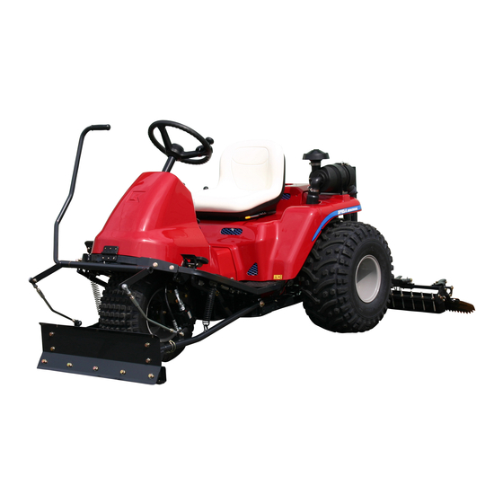
Bunker rake
Hide thumbs
Also See for SP05:
- Owner's operating manual (40 pages) ,
- Assembly and installation manual (12 pages) ,
- Assembly and installation manual (9 pages)
Table of Contents
Advertisement
Quick Links
Advertisement
Chapters
Table of Contents

Related Manuals for Baroness SP05


Summary of Contents for Baroness SP05
- Page 1 Bunker rake SP05 Service manual Serial No.#10151~ Vol.1...
- Page 2 The information described in this manual is subject to change without prior notice for improvement. When replacing parts, be sure to use genuine Baroness parts or parts designated by Kyoeisha. Note that the Baroness product warranty may not apply to defects caused by the use of parts from other companies.
-
Page 3: Table Of Contents
Contents Specifications ............7-2 Safety ................1-1 Special tools ............7-3 Removal and installation of each section ....7-4 Safety instruction .............1-2 Inspection and repair of each section ....7-10 Jacking up the machine ..........1-5 Safety labels and operation labels ......1-5 Work machine and mower unit ......8-1 Disposal ..............2-1 Maintenance ............8-2 Specifications ............8-2... - Page 4 Contents...
-
Page 5: Safety
Safety Safety instruction ..........1-2 Safety instructions ...........1-2 Before operating the machine ......1-2 When operating or transporting the ....1-3 machine Maintenance and storage .......1-4 Jacking up the machine ........1-5 Safety labels and operation labels ....1-5 Page 1-1... -
Page 6: Safety Instruction
Safety Safety instruction and the following must be thoroughly understood: Safety instructions The basic safety precautions for operating a ride-on bunker rake. Danger Danger Controlling the machine by applying the brake when it begins to slide on a slope is This machine is designed to ensure safe difficult. -
Page 7: When Operating Or Transporting The
Safety Fuel is highly flammable so make sure that Never drive the machine across a slope you take the following precautions when unless the machine is designed to do so. handling it. Never drive the machine on a slope with Store fuel in containers specifically an angle of gradient that is greater than designed for this purpose. -
Page 8: Maintenance And Storage
Safety Before leaving the operator’s seat: Before servicing or adjusting the machine, be sure to disconnect the battery. To remove Move the machine to a level surface. the battery, disconnect the negative battery Lower the machine. cable first. To install the battery, connect the Set the parking brake. -
Page 9: Jacking Up The Machine
Consult a Baroness dealer or Kyoeisha Safety labels and operation labels when major repairs or assistance is required. For safety and maximum performance, use Warning genuine Baroness parts and accessories. - Page 10 Safety Page 1-6 Safety labels and operation labels...
-
Page 11: Disposal
Disposal Waste disposal ..........2-2 Page 2-1... -
Page 12: Waste Disposal
Disposal Waste disposal Make sure that waste generated when servicing or repairing the machine is disposed of in accordance with local regulations. (e.g. waste oil, antifreeze batteries, rubber products, and wires etc.) Page 2-2 Waste disposal... -
Page 13: Maintenance Standards And Maintenance
Maintenance standards and maintenance Unit conversion table ........3-2 Inch–millimeter conversion table .....3-2 US unit–SI unit conversion table .....3-3 List of maintenance standards ......3-4 Tightening torques ..........3-5 Standard tightening torques ......3-5 Principal tightening torques ......3-8 Jacking up the machine ........3-9 Jack-up points ..........3-9 Lubrication .............3-10 Grease points ..........3-10 Page 3-1... -
Page 14: Unit Conversion Table
Maintenance standards and maintenance Unit conversion table Inch–millimeter conversion table 1 mm = 0.03937 in 1 in = 25.4 mm Fractions Decimals Fractions Decimals 1/64 0.015625 0.397 33/64 0.515625 13.097 1/32 0.03125 0.794 17/32 0.53125 13.494 3/64 0.046875 1.191 35/64 0.546875 13.891 1/16... -
Page 15: Us Unit-Si Unit Conversion Table
Maintenance standards and maintenance US unit–SI unit conversion table To Convert Into Multiply By Miles Kilometers 1.609 Yards Meters 0.9144 Feet Meters 0.3048 Linear Measurement Feet Centimeters 30.48 Inches Meters 0.0254 Inches Centimeters 2.54 Inches Millimeters 25.4 mile Square Miles Square Kilometers 2.59 Square Feet... -
Page 16: List Of Maintenance Standards
Maintenance standards and maintenance List of maintenance standards SP05 Model Vanguard 356447 Maximum no-load engine speed 3,000±100 rpm Governed idle 1,400±100 rpm Spark plug gap 0.76 mm (0.030 in) Champion RC12YC Spark plug torque 20 N-m (177.02 lb-in) Armature air gap 0.20 - 0.30 mm (0.008 - 0.012 in) -
Page 17: Tightening Torques
Maintenance standards and maintenance Exposed threaded portion of the 20 mm (0.79 in) connecting shaft Work machine Screw-in depth of the L-ball for 15 mm (0.59 in) the front blade Tightening torques Standard tightening torques Bolts and screws Unless otherwise instructed, tighten bolts or nuts by the specified torque using an appropriate tool. Excessive tightening of a screw may cause it to become loose or damaged. - Page 18 Maintenance standards and maintenance General bolts Strength class: 4.8 Nominal diameter tib3yb-001 kgf-cm lb-in 3 - 5 30.59 - 50.99 26.55 - 44.26 7 - 9 71.38 - 91.77 61.96 - 79.66 14 - 19 142.76 - 193.74 123.91 - 168.17 29 - 38 295.71 - 387.49 256.68 - 336.34...
- Page 19 Maintenance standards and maintenance Hydraulic hose The tightening torques for union joints and union adaptors with parallel pipe threads (G, PF) are shown in the table below. A union joint or adaptor will not become loose or leak as long as it is tightened by the specified torque.
-
Page 20: Principal Tightening Torques
Maintenance standards and maintenance Principal tightening torques SP05 When tightening the following bolts and nuts, tighten them by the torques specified below. As for adhesive agent, apply mid-strength screw lock (ThreeBond 1322, anaerobic extra-strength sealants). Tightening torque Adhesive Section Code... -
Page 21: Jacking Up The Machine
Maintenance standards and maintenance Jacking up the machine Front right frame Front left frame Warning Rear right frame When replacing a tire or beginning any other Rear left frame maintenance or repairs, be sure to chock the Front right frame wheels to prevent the machine from moving. -
Page 22: Lubrication
Maintenance standards and maintenance Rear right frame rwyt62-004 Jack-up points_004 Rear left frame 8bq62b-001 Grease points_001 Number of grease points Parts Two- Three- wheel wheel rwyt62-005 drive drive Jack-up points_005 Forward/reverse pedals fulcrum 1 Lubrication Brake pedal fulcrum The moving parts of this machine need to be Belt tension lever lubricated as a lack of grease on such parts could Pump neutral lever fulcrum... - Page 23 Maintenance standards and maintenance Forward/reverse pedals fulcrum Pump neutral lever fulcrum (upper part of piston pump) 8bq62b-005 Grease points_005 Front wheel axle’s rhombic flange unit 8bq62b-002 Grease points_002 Brake pedal fulcrum 8bq62b-006 Grease points_006 Rear wheel brake lever fulcrum 8bq62b-003 Grease points_003 Belt tension lever fulcrum (lower part of pump pulley)
- Page 24 Maintenance standards and maintenance 8bq62b-008 Grease points_008 Front blade lever fulcrum 8bq62b-009 Grease points_009 Front blade arm fulcrum 8bq62b-010 Grease points_010 Page 3-12 Grease points...
-
Page 25: Engine
Engine Maintenance .............4-2 Specifications ..........4-2 Adjustment ............4-3 Throttle wire ............4-3 Choke wire ............4-3 General inspection and repair ......4-3 Cooling system ..........4-3 Air cleaner ............4-4 Fuel tank ............4-4 Muffler .............4-4 Inspection and repair of each section ...4-4 Cooling system ..........4-4 Air cleaner ............4-5 Fuel cock ............4-6 Fuel filter ............4-6 Fuel pipe ............4-6... -
Page 26: Maintenance
Refer to the owner’s and service manual for Use only BARONESS genuine parts for engine details. replacement and accessories. Do not start the engine in a enclosed room,... -
Page 27: Adjustment
Engine Adjustment Throttle wire Adjustment of the speed control Maneuver the speed control lever of the operating machine to control the engine speed. Set the control lever of the operating machine at “High Speed.” The swivel (4) on the control bracket must touch the stopper (3). -
Page 28: Inspection And Repair Of Each Section
Engine Clean the screen and fan housing of dust Draining of fuel and cleaning of the fuel tank and impediments. If the fan housing needs to be removed Important from the cooling system, the engine should Make sure that fuel is drained outside. be removed. -
Page 29: Air Cleaner
Engine wear of cylinder liners and piston rings to keep Caution the engine in good condition. Clean with a brush or compressed air. Do not This air cleaner has a double layer composed of use water for cleaning engine parts, because an outer and inner elements. -
Page 30: Fuel Cock
Engine Fuel filter Caution Inspection and replacement of the fuel filter The inner element cannot be cleaned. When replacing, take care not to let dust or The fuel filter (1) can be found on the left side scraps enter the engine. of the chassis when the rear cover is opened. -
Page 31: Engine Oil
Engine Clamping of the fuel pipe is to be checked every 100 hours. Check every 6 months if 100 hours have not elapsed in 6 months. The fuel pipe is a rubber product. It deteriorates even when this equipment is not operated, so replace it with a new one every two years or when it is damaged. - Page 32 Engine 2rjzcu-002 Recommended oil_001 Change of the engine oil First time After 8 hours of operation Change of the engine oil From the second time onward For every 50 hours of operation For every 100 hours of operation or at the start of the season, whichever comes Change of the oil filter first.
-
Page 33: Removal And Installation Of Each Section
Engine Removal and installation of each Engine section Oil filter Engine Oil filler hole Oil level gauge Removal of the engine Drain plug Move the machine to a level surface. Lower Engine oil filter the rake. Apply the parking brake, stop the engine, and remove the key. - Page 34 Engine Warning Do not touch the engine and exhaust system because the high temperature may cause injury. Let them cool before starting work. Detach the connection of the battery (3). Start detaching the battery cable from the negative side (2) then detach the positive side (1).
- Page 35 Engine Detach the cable (1) from the starter motor. o3sknc-008 o3sknc-006 Removal of the engine_008 Removal of the engine_006 Fuel hose clamp Starter motor cable Fuel pump Red cap Fuel hose Remove the bolt (2), spring washer (3), Remove the nut (4) and high nut (5) in washer (4), and then remove the seat order to make it easier to remove the mount support fitting (1).
- Page 36 Engine Do not lose the four engine mounting eyes Important (5) left on the engine. When installing the engine in the machine, take care not to damage the engine, fuel hose, wiring or other parts. Mount the engine (1) on the engine base (2) of the machine.
- Page 37 Engine Block gauge Engine pulley Pump pulley Fix the engine with the two bolts and the other two bolts which have been temporarily tightened. Torque to between 14 and 19 N-m (123.91 - 168.17 lb-in). Important Fit the engine while paying attention to the vmpsh8-004 centering of the pump pulley and engine pulley.
- Page 38 Engine vmpsh8-006 vmpsh8-008 Installation of the engine_006 Installation of the engine_008 RED connector (for regulator) Plus battery cable WHITE connector (for stop solenoid) Minus battery cable Wiring RED Battery Wiring RED & BLUE Bolt Fit the throttle wire (1), choke wire (2) and Fit the fuel hose (3) to the fuel pump (2) of cleaner hose COMP (3).
-
Page 39: Hydraulic System
Hydraulic system Maintenance .............5-2 Specifications ..........5-2 Hydraulic equipment layout ......5-3 General instructions ........5-5 Hydraulic hose ..........5-5 Hydraulic fitting ..........5-6 Towing .............5-8 Neutral .............5-9 Depressurization ..........5-9 Hydraulic circuit failure ........5-9 Hydraulic circuit flow ........5-10 Traveling circuit ..........5-10 Raise/lower circuit .........5-14 Steering circuit ..........5-17 Special tools ..........5-20 Measurement method ........5-23 Note ...............5-23... -
Page 40: Maintenance
Keep people away from the maintenance methods of the SP05 hydraulic area. system. Refer to the SP05 Owner’s manual and Use an appropriate chain block, hoist and jack parts catalog for daily inspection, maintenance as needed. Securely support the lifted and handling of this machine. -
Page 41: Hydraulic Equipment Layout
Hydraulic system Hydraulic equipment layout dwb7jb-001 Hydraulic equipment layout_001 Piston pump Drive switching valve Wheel motor Check valve Valve module Raise/lower cylinder Torque generator Branch fitting Oil cooler Specifications Page 5-3... - Page 42 Hydraulic system Piston pump This is to divide or collect the flow of oil. It is This is to convert mechanical energy of the positioned almost in the center between the motor to fluid energy through reciprocal right and left rear tires. movement of the piston.
-
Page 43: General Instructions
Hydraulic system Valve module (A1) → Raise/lower cylinder lowering port Valve module (B1) → Raise/lower cylinder raising port Piston pump (B3) → Valve module input (P) Valve module (PF) → Torque generator input (IN) Valve module (T) → Return to hydraulic tank Gauge port (G) Pressure measurement port for raise/lower cylinder about 10 MPa (1,450.38 psi, 101.97 kgf/cm... -
Page 44: Hydraulic Fitting
Hydraulic system Warning Be sure to depressurize the hydraulic system before maintaining or repairing it. Stop the engine, and lower the rake. When checking for pinhole leakage of the hydraulic circuit or oil leakage of the nozzle, search for a leakage point using something like paper or cardboard, never with your bare hands. - Page 45 Hydraulic system w7s31b-009 w7s31b-006 Bite type tube fitting_009 Bite type tube fitting_006 Reference: For direct tightening, use the fitting Matchmark the zero point and further body to follow procedures 1 to 5 when using a tightening of 3/4 to one turn will cause the temporary tightening jig, and set the zero point.
-
Page 46: Towing
Hydraulic system Check to see if the O ring is properly fitted the O ring port (2), or O ring (1). Before to the groove of the main body. fitting, apply hydraulic oil or grease onto the seat surface (2) and O ring (1). Check to see that the thread part, seat surface of O ring port and O ring are free from flaws or foreign matter. -
Page 47: Neutral
Hydraulic system machine. Transport on a trailer if you have to transport the machine a long way. For the towing method, see the Owner’s manual. Important Going over the limit of towing may lead to the failure of hydraulic equipment. Also, if the machine is towed at high speed, the wheel may cease its motion. -
Page 48: Hydraulic Circuit Flow
Hydraulic system Hydraulic circuit flow Traveling circuit Two-wheel-drive forward vw1lkw-002 Two-wheel-drive forward_001 Page 5-10 Hydraulic circuit flow... - Page 49 Hydraulic system Three-wheel-drive forward 8thrmu-002 Three-wheel-drive forward_001 Hydraulic circuit flow Page 5-11...
- Page 50 Hydraulic system Two-wheel-drive reverse 4g5oar-002 Two-wheel-drive reverse_001 Page 5-12 Hydraulic circuit flow...
- Page 51 Hydraulic system Three-wheel-drive reverse yfnegf-002 Three-wheel-drive reverse_001 Hydraulic circuit flow Page 5-13...
-
Page 52: Raise/Lower Circuit
Hydraulic system Raise/lower circuit Raise/lower cylinder neutral d844jf-002 Raise/lower cylinder neutral_001 Page 5-14 Hydraulic circuit flow... - Page 53 Hydraulic system Raise/lower cylinder raising qhyyzc-002 Raise/lower cylinder raising_001 Hydraulic circuit flow Page 5-15...
- Page 54 Hydraulic system Raise/lower cylinder lowering jtjf9j-002 Raise/lower cylinder lowering_001 Page 5-16 Hydraulic circuit flow...
-
Page 55: Steering Circuit
Hydraulic system Steering circuit Torque generator neutral hz9dml-002 Torque generator neutral_001 Hydraulic circuit flow Page 5-17... - Page 56 Hydraulic system Torque generator A rotation kpkfjt-002 Torque generator A rotation_001 Page 5-18 Hydraulic circuit flow...
- Page 57 Hydraulic system Torque generator B rotation k12aps-002 Torque generator B rotation_001 Hydraulic circuit flow Page 5-19...
-
Page 58: Special Tools
Hydraulic system Special tools Pressure gauge for high-pressure measurement Pressur: For 0 - 35 MPa For 0 - 5,076.40 psi K4701000010 For 0 - 350.90 kgf/cm Used mainly for measurement of the pressure on the high side. vasdfi-004 Pressure gauge for low-pressure measurement Pressure: For 0 - 15 MPa For 0 - 2,175.60 psi... - Page 59 Hydraulic system Packing for pressure gauge Used by inserting between the K4701000050 pressure gauge and the joint for the pressure gauge. vasdfi-005 Guage valve Used for temporarily blocking fluid of K4701000060 measurement for pressure gauge maintenance, inspection, repair etc. vasdfi-016 Joint for pressure gauge K4701000040 Used as a joint for pressure piping.
- Page 60 Hydraulic system Cast iron screw T shape fitting PT3/8 PF3/8 Used when pressure gauge used K3024000042-Y between hydraulic hoses. vasdfi-013 Special adapter PF1/4 PT3/8 Used for extension of screw T shape K3009000042-Y fitting for pressure measurement. vasdfi-015 Special adapter 1013-9 2 pieces used for extension of screw T K3009000010-Y shape fitting for pressure...
-
Page 61: Measurement Method
Hydraulic system WP210-9 Hose 1-490 Used as a hydraulic hose for K3105310490 measurement of high-pressure to ultralow-pressure. vasdfi-008 90 Adjuster elbow 1086-9 Used for extension when pressure K3008000032-Y gauge fitted to pressure measurement port. vasdfi-014 Measurement method Warning Note As mentioned in the testing procedure, the use of a pressure gauge not meeting the pressure The most effective way of solving problems in measurement standard may result in damage to... - Page 62 Hydraulic system Always clean the machine before hydraulic measurement. Remember that the machine must always be kept clean for hydraulic measurement. Contamination may lead to clogging or breakage of the hydraulic circuit. Review the measuring method before starting measurement. Before measurement, check for maladjustment, clogging or breakage.
-
Page 63: Traveling Circuit
Hydraulic system Traveling circuit vt1bvt-009 Traveling circuit_001 Measurement method Page 5-25... - Page 64 Hydraulic system In the case of forward side Remove the cap (3) of the forward side measurement port (2) of the hydraulic branch fitting (1). vt1bvt-004 In the case of forward side_004 Rear hook Start the engine and accelerate to the maximum speed.
- Page 65 Hydraulic system vt1bvt-006 In the case of forward side_007 Pressure gauge for high-pressure measurement Reverse side measurement port Apply resistance to the machine by applying a shoe link or the like of to the front hook point (7). vt1bvt-007 In the case of forward side_008 Front hook point Start the engine and accelerate to the maximum speed.
-
Page 66: Raise/Lower Circuit
Hydraulic system Raise/lower circuit z4kw7w-007 Raise/lower circuit_001 Page 5-28 Measurement method... - Page 67 Hydraulic system Lower the operating machine, stop the engine and remove the cap (3) on the oil pressure measurement port G (2) of the valve module (1) with a hexagonal wrench (4). z4kw7w-004 Raise/lower circuit_004 z4kw7w-002 Hexagonal wrench Raise/lower circuit_002 Fit the elbow (5) to the hydraulic Valve module measurement port G (2).
- Page 68 Hydraulic system z4kw7w-006 Raise/lower circuit_006 Pressure gauge for low-pressure measurement Start the engine and with the rake lowered, accelerate the engine to max. rpm. Turn the raise/lower switch to “Raise.” It is considered normal if the pressure gauge (6) reads about 10 MPa (101.97 kgf/cm ) when the raise/ lower cylinder is retracted fully.
-
Page 69: Steering Circuit
Hydraulic system Steering circuit 9idjnn-004 Steering circuit_001 Measurement method Page 5-31... - Page 70 Hydraulic system Remove the hydraulic hose (3) of the PF port Fit the pressure gauge hose (5) to the PF (2) of the valve module (1). port (2) of the valve module (1). Measure by inserting the pressure gauge (4) between the input (IN) (7) of the torque generator (6) and the PF port (2) of the valve module.
- Page 71 Hydraulic system Valve module PF port Hydraulic hose Pressure gauge for low-pressure measurement Pressure gauge hose Torque generator Input (IN) Measurement method Page 5-33...
-
Page 72: Charge Circuit
Hydraulic system Charge circuit zg85f8-004 Charge circuit_001 Page 5-34 Measurement method... -
Page 73: General Inspection And Repair
Hydraulic system Remove the upper hydraulic hose (2) of the Hydraulic cartridge filter hydraulic cartridge filter (1). Hydraulic hose Pressure gauge for ultralow-pressure measurement Elbow Hose Fit the hose (5) of the pressure gauge to the elbow (4) of the hydraulic cartridge filter. (See “Charge circuit_003.”) Start the engine and accelerate to medium speed or more. -
Page 74: Hydraulic Hose, Piping
Hydraulic system Hydraulic oil After inspection and repair Caution Important Check to see if there is any hydraulic oil In the event of hydraulic circuit failure, be sure leakage in each part after installation. Refer to to clean the circuit. the tightening torque list. -
Page 75: Bleeding
Hydraulic system Start the engine and let it run idle for at least Warning two minutes, then run at the maximum speed for one minute. When jacking up the machine, check the “Safety – Jack up.” Raise and lower the the rake, and turn the steering wheel side to side. -
Page 76: Inspection And Repair Of Each Section
Hydraulic system In the following 10 minutes, drive with the After 100 hours of First time workload being gradually increased. operation Stop the machine, check the amount of Change period From the For every 500 hydraulic oil, and fill the oil if necessary. second time hours of operation Check for oil leakage. -
Page 77: Removal And Installation Of Each Section
Hydraulic system Hydraulic oil filter Change of hydraulic oil filter Contamination of the hydraulic oil causes a failure of the hydraulic equipment. Change the hydraulic oil filter regularly. After 100 hours of First time operation From the Change period second For every 500 time hours of operation... -
Page 78: Oil Cooler
Hydraulic system Remove the hydraulic hose (1) fitted to the oil cooler (4). Remove the fitting bolt (3) of the oil cooler bracket (2). Remove the oil cooler (4) together with the oil cooler bracket (2). ai9flg-001 Removal of drive switching valve_001 Hydraulic hose Elbow Adapter... -
Page 79: Valve Module
Hydraulic system ooetiu-001 Removal of in-line check valve_001 Hydraulic hose In-line check valve Bushing rzqbbw-001 Elbow Removal of valve module_001 Elbow Wiring connector Fitting of in-line check valve Hydraulic hose Fit the bushing (3) while paying attention to Fitting bolt the direction of the in-line check valve (2). -
Page 80: Piston Pump
Hydraulic system Piston pump Caution Removal of piston pump After fitting, check for hydraulic oil leakage at each part. Remove the rear cover. (See “Main body – Refer to the tightening torque list. We assume Removal of rear cover.”) no responsibility for problems caused by Loosen the nut (2) of the tension lever abnormal tightening, tightening with excessive adjuster (1) and loosen the tension lever... - Page 81 Hydraulic system Three-wheel-drive specifications Motor mounting eye Bolt Spring washer Center nut Wheel mounting eye Hydraulic hose Motor bracket Front wheel arm Wheel motor Bolt Bolt Spring washer Adapter Adjuster elbow Fitting of front wheel motor For fitting, follow the opposite procedure of removal.
-
Page 82: Hydraulic Tank
Hydraulic system Remove the drain plug (7) under the hydraulic tank (6) and drain all the hydraulic oil. Remove the hydraulic hose (8) fitted to the hydraulic tank (6). Remove the bolt (10) used for fitting the frame (9) and the hydraulic tank (6). Remove the hydraulic tank (6). - Page 83 Hydraulic system Caution After fitting, check for hydraulic oil leakage at each part. Refer to the tightening torque list. We assume no responsibility for problems caused by abnormal tightening, tightening with excessive torque or the like of. Removal and installation of each section Page 5-45...
- Page 84 Hydraulic system Page 5-46 Removal and installation of each section...
-
Page 85: Electrical System
Electrical system Maintenance .............6-2 Specifications ..........6-3 Layout of electrical components .....6-3 Special tools ............6-4 Measurement method ........6-4 Battery .............6-4 Interlock system ..........6-5 Adjustment ............6-8 Forward/reverse pedal proximity switch ..6-8 Brake pedal switch ..........6-8 Electrical components ........6-8 Safety switches ..........6-8 Seat switch ............6-9 Forward/reverse pedal proximity switch ..6-9 Brake pedal switch ..........6-9 Light switch .............6-9... -
Page 86: Maintenance
Electrical system Maintenance This chapter briefly describes how to inspect and maintain the electrical systems of “SP05.” For daily inspection, maintenance, and handling of this machine, refer to the owner’s manual and parts catalogue for “SP05.” For details on handling the battery, refer to the instruction manual provided with it. -
Page 87: Specifications
Electrical system Specifications Layout of electrical components erq4ky-001 Layout of electrical components_001 Seat switch Buzzer Fuses Forward/reverse pedal proximity Brake pedal switch Magnet switch switch Light switch Key switch Battery Solenoid valve Raise/lower switch Interlock relays Lights Hour meter Control panel Specifications Page 6-3... -
Page 88: Special Tools
Electrical system Seat switch [NC type (Off when pressed)] switch is located on the middle right of the The seat switch is one of the safety switches operation panel. of the interlock system and is located in the Hour meter seat cushion. -
Page 89: Interlock System
Electrical system corrected. The standard temperature for the Cells specific gravity of battery electrolyte is 20°C, and the specific gravity increases or decreases Battery charging by 0.0007 as the temperature increases or Follow this procedure to fully charge the decreases by 1°C. Use the following formula to battery. - Page 90 Electrical system i7f5hf-001 Interlock system_001 Control board i7f5hf-002 Interlock system_002 LED indicator lights Page 6-6 Measurement method...
- Page 91 Electrical system Interlock system activation conditions Conditions Safety device activation Relay status indication Forward/ Seat Brake reverse Engine status Buzzer LED status pedals Occupied Depressed Neutral Start Stop Sound ○ ○ ○ ○ ○ ○ ○ ○ ○ ○ ○ ○...
-
Page 92: Adjustment
Electrical system Adjustment Forward/reverse pedal proximity switch Adjust the position of the forward/reverse pedal proximity switch so that gap A is 5 mm (0.20 in) or less when the forward and reverse pedals are in the neutral position. (See “Forward/reverse pedal proximity switch_001.”) Loosen the bolts (4) and adjust the sensor mounting plate (5) by moving it parallel to the... -
Page 93: Seat Switch
Electrical system The forward/reverse pedal proximity sensor is “OFF” when the forward and reverse pedals are in the neutral position. The engine does not start unless these three conditions are met. The same is true for the starter motor. Seat switch Vout The seat switch is located immediately below the seat, and electrical continuity normally... -
Page 94: Light Switch
Electrical system bnec97-001 Light switch_001 Light switch st96l5-001 Raise/lower switch Raise/lower switch_001 The raise/lower switch (a) is located on the Raise/lower switch lever middle right of the operation panel, and Solenoid valve electrical continuity does not exist between terminals when the switch is in the neutral The solenoid valve (3) is located behind the position. -
Page 95: Hour Meter
Electrical system Solenoid valve DOWN Manual button Connectors Solenoid coil specification Holding Voltage Resistance current DC12V 7.6Ω 1.58A SOLB SOLA Hour meter The hour meter is located in the lower right of 10MPa the operation panel, and indicates the total number of hours the engine has run. -
Page 96: General Inspection And Repair
Electrical system magnetically attracts the plunger. When the plunger comes into close contact with (1) and (2) a large current flows to the starter motor from the battery, the starter motor starts to turn and the engine starts. When the key switch is set to the “ON”... - Page 97 Electrical system Danger Danger Caution Do not handle the battery near open flames or If the electrolyte overflows, neutralize it with in a poorly ventilated area. Keep the battery bicarbonate etc. until the bubbles disappear, away from lit cigarettes and other open flames. and wash out with plenty of water.
- Page 98 Electrical system until it is firmly secured. Loose connections Caution could result in an insufficiently charged If the electrolyte overflows from the battery, battery, damaged terminals, or explosion. wipe it with a wet cloth. Failure to do so could Note: If a terminal has corroded, polish it using a wire brush or fine sandpaper, and cause damage to the instruments.
- Page 99 Electrical system When mounting the battery on the machine, Danger Danger never hold the battery terminals. Doing so Do not replace the battery near open flames or could cause the terminals to deform, resulting in a poorly ventilated area. Keep the battery in poor connections or electrolyte leaks from away from lit cigarettes and other open flames.
- Page 100 Electrical system Remove the protection cap from the new Warning battery. Charging the battery while it is mounted on the Firmly secure the positive cable (1) to the machine could cause a fire or explosion, or positive terminal (2). damage to the machine or it’s instruments. If Firmly secure the negative cable to the unavoidable, be sure to disconnect the negative negative terminal (3).
- Page 101 Electrical system Important If the electrolyte gets extremely hot, the electrode plates or other parts in the battery could deteriorate, resulting in a shorter service life. General inspection and repair Page 6-17...
- Page 102 Electrical system Page 6-18 General inspection and repair...
-
Page 103: Main Body
Main body Maintenance .............7-2 Specifications ..........7-2 Tire pressure ...........7-2 Adjustment value ..........7-2 Special tools ............7-3 Removal and installation of each section ..7-4 Wheel ..............7-4 Brake ...............7-5 Steering ............7-7 Seat ..............7-7 Lift arm ............7-8 Cover ...............7-8 Damper ............7-9 Inspection and repair of each section ..7-10 Tire ..............7-10 Brake .............7-10 Brake wire, rod ..........7-12... -
Page 104: Maintenance
Main body Maintenance Specifications Tire pressure This chapter describes the main inspection and maintenance methods of the SP05 main body. Refer to the SP05 Owner's manual and parts kgf/cm catalog for daily inspection, maintenance and Front 0.71 10.15 handling of this equipment. -
Page 105: Special Tools
Main body Special tools Drum removal jig A Used for the hanging pulley when removing K480200044D the wheel mounting eye. vasdfi-009 Drum removal jig B Used for the center hole when removing the K4802000452 wheel mounting eye. vasdfi-010 Special tools Page 7-3... -
Page 106: Removal And Installation Of Each Section
Main body Removal and installation of each section Wheel Removal of front wheel Securely set a jack at the jack-up points of the right and left of the front wheel part, and lift the tire off the ground. (See “Overhaul standard and maintenance –... -
Page 107: Brake
Main body Two-wheel-drive specifications Heat-treated bolt Three-wheel-drive specifications Remove the rear wheel (1). Rhombic flange unit Bolt Spring washer Washer Bolt Spring washer Washer Front wheel bracket Front wheel arm Bolt Wheel mounting bolt lp4z4o-003 Spring washer Removal of rear wheel_002 Washer Rear wheel Front wheel... - Page 108 Main body Special nut Insert the drum removal jig B (1). z2sgi8-010 Removal of brake drum_004 Drum removal jig A Drum removal jig B z2sgi8-008 Gear puller Removal of brake drum_002 Remove the wheel mounting eye (1) from Drum removal jig B the plate.
-
Page 109: Steering
Main body Steering Caution Removal of steering column Refer to the tightening torque list. We assume no responsibility for problems caused by Remove the front cover. (See “Cover – abnormal tightening, tightening with excessive Removal of front cover.”) torque or the like of. Remove the hydraulic hose (2) attached to the torque generator (1). -
Page 110: Lift Arm
Main body Seat Cylinder Slide handle Split pin Cover stopper Washer Rear cover Hardened flat head pin Seat mount Arm mounting fitting, right and left Split pin Spring washer Hardened flat head pin Rake hanging arm Fitting of seat Fitting of the rake hanging arm For fitting, follow the opposite procedure of removal. -
Page 111: Damper
Main body Dimple knob Front cover Cable Split pin Resin hinge Small round screw Washer Round head pin Fitting of front cover For fitting, follow the opposite procedure of removal. Caution Refer to the tightening torque list. We assume no responsibility for problems caused by abnormal tightening, tightening with excessive torque or the like of. -
Page 112: Inspection And Repair Of Each Section
Main body Brake A worn brake shoe will increase the amount of brake pedal depression, and may cause the pedal to touch the floor or result in uneven braking. Inspect the brake accordingly. Adjust the brake shoe clearance to be even on both sides. - Page 113 Main body z2sgi8-004 Disassembly and assembly of brake_004 Shoe Adjuster screw When assembling, apply grease to the sliding part. Use grease that is exclusively for brakes and never apply onto the shoe friction surface. If it adhered on the surface, remove it with brake cleaner etc.
-
Page 114: Brake Wire, Rod
Main body Adjustment of brake wire adjuster bolt Elongation of the brake wire may cause its stroke to be full, resulting in the brake being weak or locking. Adjust the pull length of the brake lever (6) with the adjuster bolt (3) of the brake wire (5). Minimize play of the brake lever (6) to adjust the brake so it is set free when the lever is released. -
Page 115: Throttle Wire, Rod
Main body Check to see if the forward/reverse pedals Compression spring fulcrum has any looseness. Compression spring Check to see if the spiral pin (7) of the Split pin trunnion lever (13) comes off, or the bearing Lever adjuster (8) rattles. Pump neutral lever shaft Forward/reverse pedals fulcrum Spiral pin... -
Page 116: Choke Wire, Rod
Main body b95bj2-001 Inspection of choke wire_001 Choke lever Check to see if the choke wire (1) is bent or broken. Check to see if the choke spring (2) is bent. qciz41-001 Inspection of throttle lever and wire_001 Throttle lever Throttle wire Choke wire, rod Depending on the frequency of use, the lever... -
Page 117: Belt
Main body V belt Adjust the nuts (2) at both ends of steering chain (1) so that the chain is neither too Adjustment of V belt tight nor slack. Lock the nuts (2) securely after adjustment. A loose belt may hop or slip. In contrast, too much tension may facilitate damage. - Page 118 Main body Page 7-16 Inspection and repair of each section...
-
Page 119: Work Machine And Mower Unit
Work machine and mower unit Maintenance .............8-2 Specifications ..........8-2 Adjustment values ...........8-2 Special tools ............8-2 Adjustments .............8-2 Rake ..............8-2 Front blade section ..........8-3 Finishing brush section ........8-4 Removal and installation of each section ..8-5 Rake ..............8-5 Front blade section ..........8-5 Sand cultivator section ........8-5 Finishing brush section ........8-5 Cargo box section ...........8-5... -
Page 120: Maintenance
Work machine and mower unit Maintenance Specifications Adjustment values This chapter briefly describes how to inspect and maintain the SP05 work machine. For daily Rake inspection, maintenance, and handling of the main unit, refer to the Owner’s Manual and Parts Fork depth (standard) 0.59... -
Page 121: Front Blade Section
Work machine and mower unit Warp board Cross-link chains Rake mounting bracket Rake fines Level concrete surface Rake Wooden board or the like Front blade section Rake mounting bracket Loosen the bolt (1) to set the small front When adjusting the cross-link chains (1), adjust blade (2). -
Page 122: Finishing Brush Section
Work machine and mower unit Adjust so that the grip of the front blade lever is not too far away from the handle. r4ma8y-001 Finishing brush section_001 Second from bottom (Light finishing) r4ma8y-002 Finishing brush section_002 Third from bottom (Medium finishing (normal use)) 5b7smu-004 Front blade section_002... -
Page 123: Removal And Installation Of Each Section
Work machine and mower unit Cross-link chains Rake holding arm Rake fulcrum pipe Nuts Washer A Washer B Fulcrum swing fitting Installation of the rake r4ma8y-004 Install the rake by reversing the steps for its removal. Finishing brush section_004 Removal and installation of each Caution section Refer to the list of tightening torques. -
Page 124: Inspection And Repair Of Each Section
Work machine and mower unit Inspect the rake pipe (1) to ensure that it is not bent (90°). Inspect the cross-link chains (2) (standard: 7 links) to ensure that they are not twisted or worn. Inspect the rake shaft (3) to ensure that it is not worn. -
Page 125: Front Blade Section
Work machine and mower unit adjusted clearance in the L-ball of the front blade and the adjusted height of the front blade when raised are within the specified values. (Refer to “Specifications: Adjustments.”) 5b7smu-002 Front blade section_001 Spring pin Connecting shaft Inspect the spring hooks (3) to ensure that they are not bent and have not stretched. -
Page 126: Sand Cultivator Section
Work machine and mower unit Finishing brush section Spring hooks Delta pins Inspect the brush mounting frame (1) to ensure that it is not bent. Small front blade Inspect the brush (2) to ensure that it is not Sand cultivator section bent, worn, or otherwise damaged. -
Page 127: Troubleshooting
Troubleshooting Engine problems ..........9-2 Traveling problems .........9-4 Steering problems ...........9-5 Work machine and mower unit problems ..9-6 Page 9-1... -
Page 128: Engine Problems
Troubleshooting Engine problems Problem Cause Reference The interlock system has been activated. Electrical system - (The seat is not occupied, the brake is not Measurement methods - depressed, or the forward or reverse pedal is not Interlock system in the neutral position.) A component in the interlock system has failed. - Page 129 Troubleshooting Problem Cause Reference Engine - Inspection and repair The air cleaner element is clogged. of each section - Air cleaner The engine cranks but will not Maintenance manual for start. The engine is not compressing properly. engine The fuel type is incorrect. Instruction manual for engine The interlock system has been activated.
-
Page 130: Traveling Problems
Troubleshooting Traveling problems Problem Cause Reference Hydraulic system - General The hydraulic oil level is low. inspection and repair - Hydraulic oil Main unit - Inspection and The pump V-belt is loose. repair of each section - V-belt Owner’s Manual for this The unload valve is being pressed. -
Page 131: Steering Problems
Troubleshooting Steering problems Problem Cause Reference The engine speed is low. Main unit - Inspection and The tire pressure is low. repair of each section - Tires Main unit - Inspection and The steering chain is too tight. repair of each section - Steering chain Main unit - Removal and The front arm bearing is faulty. -
Page 132: Work Machine And Mower Unit Problems
Troubleshooting Work machine and mower unit problems Problem Cause Reference The engine speed is low. The chain suspending the rake section has come Work machine and mower unit off. - Adjustments - Rake section Hydraulic system - Removal A pin for the raise/lower cylinder has fallen off. and installation of each section - Raise/lower cylinder Electrical system - Electrical... -
Page 133: Reference
Troubleshooting Problem Cause Reference Work machine and mower unit The warp board of the rake section has become - Inspection and repair of each worn. section - Rake section Work machine and mower unit A fork blade has become worn. - Inspection and repair of each The raked surface is not section - Rake section... - Page 134 Troubleshooting Page 9-8 Work machine and mower unit problems...
- Page 135 Reference Specifications ..........10-2 Maintenance schedule ........10-3 Hydraulic circuit diagram ......10-5 Electric wiring diagram .........10-6 Consumable parts list ........10-7 Page 10-1...
-
Page 136: Specifications
Reference Specifications SP05 Total length 215 cm (846.46 in) Total width 190 cm (748.03 in) Machine dimensions Total height 120 cm (472.44 in) Wheelbase 105 cm (413.39 in) Tread 107 cm (421.26 in) Gross mass (with rakes) 480 kg (1,058.22 lb) Two-wheel drive 0 - 16.0 km/h (0 - 13.1 m/ph) -
Page 137: Maintenance Schedule
Reference Maintenance schedule The maintenance schedule is as follows: Caution When performing maintenance, use appropriate tools, suitable for the purpose. ○ … Inspection, adjustment, refill, and cleaning ● … Replacement Every Every Every Every Every Every Before After Maintenance items Remarks work work... - Page 138 Reference Every Every Every Every Every Every Before After Maintenance items Remarks work work year hours hours hours hours hours Cleaning/inspection of ○ each part Main unit Activation of safety ○ devices Tightening of each part ○ Cleaning/inspection of Work ○...
-
Page 139: Hydraulic Circuit Diagram
Reference Hydraulic circuit diagram 6inb7c-001 Hydraulic circuit diagram_001 Hydraulic circuit diagram Page 10-5... -
Page 140: Electric Wiring Diagram
Reference Electric wiring diagram Electric wiring diagram_001 Page 10-6 Electric wiring diagram... -
Page 141: Consumable Parts List
Finishing brush SP05---1002Z0 Finishing brush 1.0 (NY) Machine Finishing brush adjustment wire K1160089000 Adjustment wire 890 Trapezoidal cultivator fitting SP05---0909ZD Trapezoidal cultivator fitting Cultivator wire K1160082000 Cultivator wire 820 Smoother plate SP05---0722ZD Smoother plate 20-15° Consumable parts list Page 10-7... - Page 142 SP05----SM--USZ/10A-00-S.K...
Need help?
Do you have a question about the SP05 and is the answer not in the manual?
Questions and answers