Baroness SP05A Owner's Operating Manual
Bunker rake
Hide thumbs
Also See for SP05A:
- Owner's operating manual (80 pages) ,
- Owner's operating manual (76 pages) ,
- Owner's manual (89 pages)

Related Manuals for Baroness SP05A


Summary of Contents for Baroness SP05A
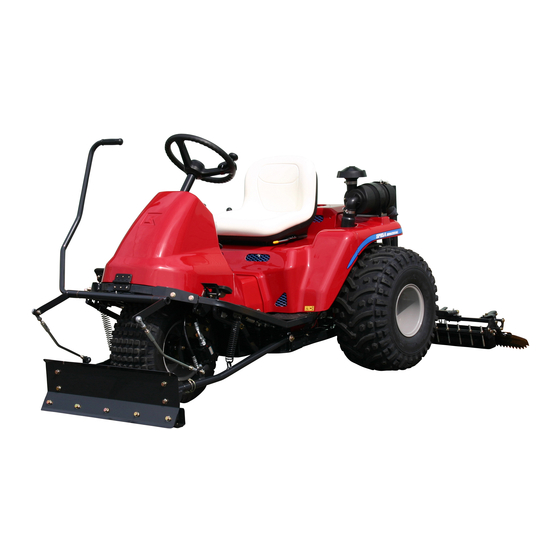
- Page 1 Bunker Rake Owner's operating manual "Required reading" Read this manual and the owner's manual for the engine before using the machine. Serial No.11001- Ver.1.1...
- Page 2 SP05A Greeting Thank you for purchasing the Baroness machine. Spark arrester This manual explains proper handling, adjustment, and inspection of your machine. Important Prior to use, carefully read this manual to thoroughly understand the contents for safe and The engine in this product is not equipped correct operation.
- Page 3 The information described in this manual is subject to change for improvement without prior notice. When replacing parts, be sure to use genuine Baroness parts or parts designated by Kyoeisha. Note that the Baroness product warranty may not apply to defects caused by the use of parts from other companies.
- Page 4 SP05A Introduction Warning Symbols This manual uses the following warning symbols for handling precautions that are important for your safety. Warning symbol 696cq5-001 This symbol indicates the articles regarding “Danger,” “Warning,” or “Caution.” Those articles describe important safety precautions and so read them carefully to understand completely before operating the machine.
-
Page 5: Table Of Contents
SP05A Contents Safety............... Page 1-1 Safe Operating Practices........Page 1-2 Disposal............Page 2-1 Waste Disposal..........Page 2-2 Product Overview........... Page 3-1 Specifications..........Page 3-2 Names of Each Section........Page 3-3 Safety Signs and Instruction Signs....Page 3-4 Handling Instructions........Page 4-1 Inspection Before Use........Page 4-2 Tightening torques........ - Page 6 SP05A Contents...
-
Page 7: Safety
SP05A Safety Safe Operating Practices....... Page 1-2 Training...........Page 1-2 Preparation..........Page 1-2 Operation..........Page 1-3 Maintenance and storage....... Page 1-4 Page 1-1... -
Page 8: Safe Operating Practices
SP05A Safety Failure to adequately follow these safety Being driven too fast precautions may cause an accident resulting in Inadequate braking injury or death. The type of machine is unsuitable for its task Danger Danger Lack of awareness of the effect of... - Page 9 SP05A Safety Add fuel before starting the engine. Machine speeds should be kept low on Never remove the cap of the fuel tank or slopes and during tight turns. add fuel while the engine is running or Stay alert for humps and hollows and when the engine is hot.
- Page 10 SP05A Safety Never operate while people, especially Only cover the machine with a sheet after children, or pets are nearby. hot parts have sufficiently cooled down. Slow down and use caution when making Never store the equipment with fuel in the turns and crossing roads and sidewalks.
- Page 11 SP05A Safety Make sure that parts such as wires are not touching each other and that their covers have not come off. Keep hands and feet away from moving parts. If possible, do not make adjustments with the engine running.
- Page 12 SP05A Safety Page 1-6 Safe Operating Practices...
-
Page 13: Disposal
SP05A Disposal Waste Disposal........Page 2-2 About the Waste disposal....... Page 2-2 Page 2-1... -
Page 14: Waste Disposal
SP05A Disposal Waste Disposal About the Waste disposal Make sure that waste generated when servicing or repairing the machine is disposed of in accordance with local regulations. (e.g. waste oil, antifreeze batteries, rubber products, and wires etc.) Page 2-2 Waste Disposal... -
Page 15: Product Overview
SP05A Product Overview Specifications......... Page 3-2 Specifications..........Page 3-2 Sound pressure level......Page 3-2 Sound power level........Page 3-2 Vibration level......... Page 3-3 Names of Each Section......Page 3-3 Serial Number Plate........Page 3-3 Evaporative Emissions Control Plate..Page 3-4 Safety Signs and Instruction Signs..Page 3-4 About Safety Signs and Instruction Signs............Page 3-4... -
Page 16: Specifications
SP05A Product Overview Specifications Specifications Model SP05A (2WD) SP05A (3WD) Total length 215 cm (with blade 230 cm) Dimensions Total width 190 cm Total height 120 cm Weight (with rake) 430 kg 457 kg Minimum turning radius 339 cm Model... -
Page 17: Names Of Each Section
SP05A Product Overview Vibration level Steering wheel Front cover Hand-arm vibration Blade (option) This machine was confirmed to transmit a Front tire maximum vibration level of less than 2.5m/s Traveling pedal hands and arms by measuring identical Oil gauge machines in accordance with the procedure Cultivator (option) specified in ISO5349-1:2001,ISO5349-2:2001. -
Page 18: Safety Signs And Instruction Signs
If they are damaged, become dirty, or peel off, replace them with new ones. Part numbers for decals that need to be replaced are listed in the parts catalog. Order them from a Baroness dealer or Kyoeisha. Positions of Safety Decals and Instruction h2edhm-001... -
Page 19: Explanation About Safety Decals And Instruction Decals
SP05A Product Overview Explanation about Safety Decals and Instruction Decals SP05---0560C0 Decal, operation Warning Read the manual. Warning Apply the parking brake, stop the engine, remove the ignition key, and then leave the machine. Applying the parking brake – While depressing the parking brake pedal, depress the lock pedal. - Page 20 SP05A Product Overview K4205001940 Decal, fire prohibited Danger Danger Keep away from fire. qigqnx-041 K4205001910 Decal, caution to getting entangled Danger Danger Watch for rotating parts - Keep your hands away from qigqnx-028 the belts while the engine is running.
-
Page 21: Handling Instructions
SP05A Handling Instructions Inspection Before Use......Page 4-2 Operation of Each Section....Page 4-21 Rake............Page 4-2 Precautions for Operating the Machine..........Page 4-21 Blade............Page 4-2 Cautions for when You Leave the Cultivator..........Page 4-3 Machine..........Page 4-21 Finishing Brush........Page 4-3 Operation Decals........Page 4-21 Oil cooler..........Page 4-3... -
Page 22: Inspection Before Use
SP05A Handling Instructions Blade Inspection Before Use Inspection of Blade Be sure to perform an inspection before you start using the machine so that you will be able to take Due to frequent use or damage caused during advantage of its optimum performance for a long use or transportation, it may become difficult to period of time. -
Page 23: Cultivator
SP05A Handling Instructions Make sure that the brush is not bent or Connecting shaft excessively worn. Hook spring Oil cooler Delta pin Small blade Inspection of Oil Cooler Cultivator Make sure that there is no damage to the oil cooler. - Page 24 SP05A Handling Instructions Make sure that the oil level is at the middle Remove the bolts, and then remove the of the oil gauge. cover. olekci-001 dmhzyz-002 Inspection of Hydraulic Oil_001 Hydraulic Oil Supply_002 Oil gauge Bolt Cover Check underneath the machine for oil leakage.
-
Page 25: Hydraulic Hoses
SP05A Handling Instructions Remove the tank cap, pour new oil from the Change of Hydraulic Oil fill port until the oil level reaches the middle of the oil gauge on the hydraulic tank, then Warning replace the tank cap. The hydraulic tank capacity is... -
Page 26: Air Cleaner
SP05A Handling Instructions Air Cleaner Caution When cleaning the air cleaner element, do Inspection of Air Cleaner not use a petroleum solvent. For details on handling the engine, please refer When cleaning and drying the air cleaner to the separate Engine Handling Manual. -
Page 27: Battery
SP05A Handling Instructions Make sure that the battery fluid level is Change of Air Cleaner between the UPPER LEVEL (maximum fluid level line) and the LOWER LEVEL For details on handling the engine, please refer (minimum fluid level line). to the separate Engine Operating Manual. -
Page 28: Tire
SP05A Handling Instructions Supply of Battery Fluid Tire size Pneumatic pressure Front wheel (PD21 x For details on handling the battery, please refer 70 kPa (0.7 kgf/cm 11.00 - 10) to the separate Battery Instruction Manual. Rear wheel (25 x 13.00 40 kPa (0.4 kgf/cm... -
Page 29: Steering Wheel
SP05A Handling Instructions Position the machine so that the engine will Steering wheel be level, then insert the oil level gauge all the way to check the oil level. Inspection of Steering Chain Excessive play with a loose steering chain may... - Page 30 SP05A Handling Instructions Re-place the oil filler cap. Supply of Engine Oil For details on handling the engine, please refer to the separate Engine Handling Manual. Important Do not fill too much engine oil. Otherwise, the engine may be damaged.
-
Page 31: Fuel Filter
SP05A Handling Instructions After checking the oil level with the oil level Important gauge, add more engine oil if it is Securely tighten the oil level gauge and oil insufficient. filler cap. The engine oil quantity (including the oil If they are insufficiently tightened or there is filter) is approximately 1.6 dm... -
Page 32: Fuel
SP05A Handling Instructions Fuel Change of Fuel Filter Inspection of Fuel Quantity Caution Observe the fuel gauge located on the fuel The fuel filter cannot be disassembled or tank to check the fuel level. cleaned. If dust or dirt accumulates in the fuel filter, the fuel flow will become insufficient. -
Page 33: Tightening Torques
SP05A Handling Instructions Tightening torques Standard tightening torques Bolts and Nuts Important A number of bolts are used in each part of this machine. Be sure to re-tighten the bolts and nuts, because they may be loosened at the earlier stage of the use. - Page 34 SP05A Handling Instructions General bolt Strength classification 4.8 Nominal diameter tib3yb-001 kgf-cm lb-in 3 - 5 30.59 - 50.99 26.55 - 44.26 7 - 9 71.38 - 91.77 61.96 - 79.66 14 - 19 142.76 - 193.74 123.91 - 168.17 29 - 38 295.71 - 387.49...
-
Page 35: Principal Tightening Torques
SP05A Handling Instructions Principal tightening torques Tightening Torque by Model SP05A Tighten the following bolts and nuts at the torque specified in the table. For thread locking adhesive, apply a middle strength thread locker (ThreeBond 1322 anaerobic adhesives). Tightening torque... -
Page 36: Adjustment Before Operating
SP05A Handling Instructions Adjustment of Seat Adjustment Before Operating Use the seat adjustment lever to adjust the seat. Adjustment of Steering Wheel Adjust the position according to the operator's body size. Warning Since it is dangerous, do not adjust the steering wheel while traveling. -
Page 37: Adjustment Of Rake
SP05A Handling Instructions Raise and lower the rake to check that it Speed adjustment plate lightly touches the rake stopper. Bolt Forward pedal Reverse pedal Slow Fast Adjustment of Rake The rake can be adjusted with the nut. On a level surface, lower the rake, and... -
Page 38: Adjustment Of Finishing Brush
SP05A Handling Instructions When used for light finishing, adjust to the Adjustment of Finishing Brush position second from the bottom. The height of the finishing brush can be adjusted with the clutch lever. Adjust the height of the brush from the ground according to the bunker conditions. - Page 39 SP05A Handling Instructions When used for normal finishing, adjust to the When used for heavy finishing, adjust to the position third from the bottom. highest position. f5zgea-003 f5zgea-004 Adjustment of Finishing Brush_003 Adjustment of Finishing Brush_004 Adjustment Before Operating Page 4-19...
-
Page 40: Procedure To Start / Stop Engine
SP05A Handling Instructions Gradually move the throttle lever to "High". Procedure to Start / Stop Engine Procedure to Stop Engine Start / Stop of Engine Set the traveling pedal in neutral position. Procedure to Start Engine Apply the parking brake. -
Page 41: Operation Of Each Section
SP05A Handling Instructions Operation of Each Section Ignition key Throttle lever Precautions for Operating the Machine Up/down lever Tilt lever Caution Throttle Lever Under any circumstances drive the machine at such a speed that you can stop it The throttle lever is located on the right side immediately for emergencies. -
Page 42: Up/Down Lever
SP05A Handling Instructions Up/Down Lever 2WD/3WD Selector Lever Important Warning If the engine rpm is low, the rake will not be When switching between 2WD and 3WD raised and lowered due to insufficient operation, make sure to stop the machine hydraulic oil. -
Page 43: Traveling Pedal
SP05A Handling Instructions Traveling Pedal Brake Pedal The traveling pedal is located in the right foot Caution area. When depressed forward, the machine travels When leaving the driver's seat, park the forward. When depressed backward, the machine on a stable, flat surface and be sure machine travels in reverse. -
Page 44: Front Cover
SP05A Handling Instructions Open the front cover, and then tilt it forward Front Cover until the wire is fully extended. Caution Do not open the cover in strong winds. Caution When closing the cover, be careful not to pinch your hands. -
Page 45: Instruments
SP05A Handling Instructions Open the rear cover, and then lift it until the Instruments gas spring is fully extended. Instruments on the Operation Panel uemj7o-004 Rear Cover_002 kz7ka6-004 Rear cover Instruments on the Operation Panel_001 Gas spring Hour meter When closing the rear cover, slowly lower it... -
Page 46: Travel Of Machine
SP05A Handling Instructions Loosen the lock nuts. Travel of Machine Operating Procedure Start the engine.((See "Procedure to Start Engine" (Page 4-20) .) Raise the rake. Firmly depress the brake pedal and release the lock fitting to release the brake pedal. -
Page 47: Operations
SP05A Handling Instructions Important Important Before towing, be sure to open the unload If the engine rpm is low, the rake will not be valves in two locations. raised and lowered due to insufficient hydraulic oil. Remove the wheel stoppers, and then firmly... -
Page 48: Blade
SP05A Handling Instructions Gradually move the throttle lever to "High", At the bunker area where the operation is to and rev up the engine to MAX (3,000 rpm). be started, shift the up/down lever to the "DOWN" position to lower the rake. - Page 49 SP05A Handling Instructions Firmly depress the brake pedal and release Caution the lock fitting. If the blade is raised, do not touch the lifting The parking brake is released at the same lever. time. Caution When getting on and off the machine, watch out the blade lever lest you should get your foot caught on it and fall.
-
Page 50: Cultivator
SP05A Handling Instructions Pull the blade lever toward you to raise the ・ Warning blade. When switching between 2WD and 3WD operation, make sure to stop the machine completely. Caution Do not enter or leave a bunker via a steep slope or extremely uneven ground. - Page 51 SP05A Handling Instructions Start the engine.((See "Procedure to Start Gradually move the throttle lever to "High", Engine" (Page 4-20) .) and rev up the engine to MAX (3,000 rpm). Important If the engine rpm is low, the rake will not be raised and lowered due to insufficient hydraulic oil.
-
Page 52: Finishing Brush
SP05A Handling Instructions At the bunker area where the operation is to At the bunker area where the operation is to be started, squeeze the clutch lever and pull be started, shift the up/down lever to the the cultivator lever toward you. - Page 53 SP05A Handling Instructions Start the engine.((See "Procedure to Start Gradually move the throttle lever to "High", Engine" (Page 4-20) .) and rev up the engine to MAX (3,000 rpm). Important If the engine rpm is low, the rake will not be raised and lowered due to insufficient hydraulic oil.
-
Page 54: Transporting
SP05A Handling Instructions At the bunker area where the operation is to be started, shift the up/down lever to the "DOWN" position to lower the rake. The finishing brush is lowered at the same time. 3oc72m-001 Finishing Brush_004 Up/down lever... -
Page 55: Maintenance
SP05A Maintenance Maintenance Precautions...... Page 5-2 Maintenance Schedule......Page 5-2 Specified Values........Page 5-4 Main Consumable Parts......Page 5-5 Jacking up the machine......Page 5-5 About the Jacking up the machine..Page 5-5 Jack-up Points........Page 5-6 Greasing..........Page 5-8 About Greasing........Page 5-8... -
Page 56: Maintenance Precautions
Use tools appropriate for each maintenance operation. Caution For the safe and best performance of your machine, use Baroness genuine parts for replacement and accessories. Please note that our product warranty may be void if you use non-genuine parts for replacement or accessories. - Page 57 SP05A Maintenance Maintenance item Battery ○ △ Battery fluid ○ Cleaning the exterior ○ Tightening the parts ○ Interlock system ○ Emergency switch ○ Electrical wiring ○ Knife ○ Steering chain ○ Cutting (or brush) height ○ Greasing, oiling ○...
-
Page 58: Specified Values
SP05A Maintenance Replace the steering cylinder hoses every 2 years. Specified Values Fuel tank capacity 15.0 dm (15.0 L) Hydraulic tank capacity Shell Tellus S2V32 (or equivalent) 15.0 dm (15.0 L) Engine oil capacity (including oil filter) Summer: SAE30, Winter: SAE20 1.6 dm... -
Page 59: Jacking Up The Machine
SP05A Maintenance Main Consumable Parts Jacking up the machine About the Jacking up the machine Part Name Code Engine oil filter PL492932S Warning Fuel filter PL691035 Spark plug PL491055S When replacing a tire or beginning any other maintenance or repairs, be sure to chock the... -
Page 60: Maintenance (Attachments)
SP05A Maintenance Front right frame Jack-up Points rwyt62-002 Jack-up Points_002 Reinforcing plate Front left frame Important One nut is used to install the reinforcing plate. Be careful that the jack does not hit the nut. rwyt62-001 Jack-up Points_001 Jack-up Points... - Page 61 SP05A Maintenance Rear right frame rwyt62-004 Jack-up Points_004 Rear left frame rwyt62-005 Jack-up Points_005 Jacking up the machine Page 5-7...
-
Page 62: Greasing
SP05A Maintenance Greasing No. of Greasing Location About Greasing Points Since there may be adhesion or damage due to Traveling pedal fulcrum lack of grease on moving parts, they must be greased. Brake pedal fulcrum Add urea-based No. 2 grease in accordance Belt tension lever with the Maintenance Schedule. - Page 63 SP05A Maintenance Brake pedal fulcrum Pump neutral lever fulcrum (above piston pump) 8bq62b-003 Greasing Points_003 8bq62b-005 Belt tension lever (below pump pulley) Greasing Points_005 Front wheel shaft rhombic flange unit 8bq62b-006 8bq62b-004 Greasing Points_006 Rear wheel brake lever fulcrum Greasing Points_004...
-
Page 64: Change Of Fork Prong Bar
SP05A Maintenance Maintenance (Attachments) Change of Fork Prong Bar Caution When handling a sharp fork prong bar, be sure to wear gloves. When wear of the fork prong bar results in no margin for tightening the nut on the fork prong bar, replace the fork prong bar. -
Page 65: Change Of Small Blade
SP05A Maintenance Change of Small Blade Change of the Cultivator Fitting When wear of the small blade causes a Caution reduction in the amount of sand that is lifted up, replace the small blade. When removing the cultivator, be careful not to pinch your hands. - Page 66 SP05A Maintenance Remove the bolts, and then replace the Caution trapezoidal cultivator fittings. Place the finishing brush on level surface. Remove the bolts, and then replace the finishing brush. 5qpzvh-003 Change of the Cultivator Fitting_003 Bolt Trapezoidal cultivator fitting 9l7sqe-002...
-
Page 67: Maintenance (Main Body)
SP05A Maintenance Maintenance (Main Body) Removing/Installing Tires Front Tire Follow the steps below to remove the front tire: Securely place the jack beneath the jack-up points of the front left/right frame area, and then raise it until the tire lifts off the ground. - Page 68 Spring washer C Washer C Front wheel Caution Refer to the Tightening Torque table. Note that the Baroness product warranty may not apply to defects caused by incorrect or overtorque tightening etc. Important Tighten the bolts in the tightening order (crosswise).
-
Page 69: Adjustment Of Belt Tension
Remove the bolts. Remove the tire from the wheel mounting seat. Caution See "Tightening torques" (Page 4-13) . Note that the Baroness product warranty may not apply to defects caused by incorrect or overtorque tightening etc. Important vottpg-001 Tighten the bolts in the tightening order Adjustment of Pump Drive Belt_001 (crosswise). -
Page 70: Adjustment Of Steering Chain
SP05A Maintenance After making adjustments, firmly secure the High nut nuts. Spring cover Adjustment of Brake Tension fulcrum fitting Warning Belt Make sure that the brake wire is not cracked Spring or damaged. Tension pulley Engine pulley Pump pulley Warning... -
Page 71: Adjusting The Neutral Position Of The Piston Pump
SP05A Maintenance ・ If the brake lever play is too small, the ・ If the brake lever play is too small, the braking power will be increased and the braking power will be excessive and the brake pedal will be hard. - Page 72 SP05A Maintenance Remove the cotter pin and washer at the Piston pump pedal end, and then remove the end of the push-pull cable. Camshaft Loosen the adjustment nuts. hsn2jo-003 Adjusting the Neutral Position of the Piston Pump_001 Push-pull cable hsn2jo-004...
-
Page 73: Long-Term Storage
SP05A Maintenance Insert the push-pull cable, and then install Change of Fuse the washer and cotter pin. Fuses Warning When performing maintenance on the electrical system, be sure to remove the negative battery wire. Caution If a fuse blows, a short may have occurred hsn2jo-003 within the electrical circuit. - Page 74 SP05A Maintenance Page 5-20 Long-Term Storage...
- Page 79 Head Office 1-26, Miyuki-cho, Toyokawa, Tel : (0533) 84 - 1390 Fax : (0533) 89 - 3623 Aichi-Pref. 442-8530 Japan. SP05A---UM--USZ/15J-00-S.K C 201600[SP05A_EV2016AA00]...
Need help?
Do you have a question about the SP05A and is the answer not in the manual?
Questions and answers