Baroness SP05A Owner's Operating Manual
Bunker rake
Hide thumbs
Also See for SP05A:
- Owner's operating manual (79 pages) ,
- Owner's operating manual (76 pages) ,
- Owner's manual (89 pages)

Related Manuals for Baroness SP05A


Summary of Contents for Baroness SP05A
- Page 1 Bunker Rake Owner's Operating Manual Serial No. SP05A:20699- "Required reading" Read this manual and the Owner's Manual for the engine before using the machine. Original Instructions Ver.1.2...
- Page 2 SP05A Greeting Thank you for purchasing the Baroness machine. This manual explains proper handling, adjustment, and inspection of your machine. Prior to use, carefully read this manual to thoroughly understand the contents for safe and correct operation. We hope you will use the machine safely, and take advantage of its best performance.
- Page 3 The information described in this manual is subject to change for improvement without prior notice. When replacing parts, be sure to use genuine Baroness parts or parts designated by Kyoeisha. Note that the Baroness product warranty may not apply to defects caused by the use of parts from other companies.
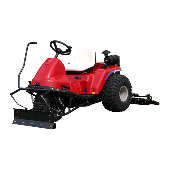
- Page 4 SP05A Introduction Purpose This machine is intended for leveling bunkers at golf courses. Do not use this machine in any other way than its intended purpose, and do not modify the machine. Operating this machine for other purposes and modifying it may be very dangerous and may cause damage to the machine.
-
Page 5: Table Of Contents
SP05A Contents Safety .............. Page 1-1 Safe Operating Practices .......Page 1-2 Disposal ............Page 2-1 Recycle and Waste Disposal ......Page 2-2 Product Overview .......... Page 3-1 Specifications ..........Page 3-2 Names of Each Section ......... Page 3-3 Safety Signs and Instruction Signs ....Page 3-5 Handling Instructions ........ - Page 6 SP05A Contents...
-
Page 7: Safety
SP05A Safety Safe Operating Practices ...... Page 1-2 Training ..........Page 1-2 Preparation ..........Page 1-2 Operation ..........Page 1-3 Maintenance and storage ...... Page 1-4 Page 1-1... -
Page 8: Safe Operating Practices
SP05A Safety Failure to adequately follow these safety Never allow children or people unfamiliar precautions may cause an accident resulting in with these instructions to use or service the injury or death. machine. Local regulations may restrict the age of the... - Page 9 SP05A Safety If fuel is spilled, do not attempt to start the Use extra care while operating machine with engine but move the machine away from a grass catcher or other attachments. the area of spillage and avoid creating any They can affect the stability of the machine.
- Page 10 SP05A Safety When transporting the machine on a truck or Use jack stands to support components a trailer, set the parking brake, stop the when required. engine, and fasten the machine to the truck Carefully release pressure from components with a rope or other suitable restraining with stored energy.
-
Page 11: Disposal
SP05A Disposal Recycle and Waste Disposal ....Page 2-2 About Recycle ........Page 2-2 About the Waste disposal ...... Page 2-2 Page 2-1... -
Page 12: Recycle And Waste Disposal
SP05A Disposal Recycle and Waste Disposal About Recycle Recycling battery etc. is recommended for environmental conservation and economical use of resources. It may be required by local laws. About the Waste disposal Make sure that waste generated when servicing or repairing the machine is disposed of in accordance with local regulations. -
Page 13: Product Overview
SP05A Product Overview Specifications ........Page 3-2 Specifications .........Page 3-2 Sound pressure level ......Page 3-3 Sound power level ......... Page 3-3 Vibration level ........Page 3-3 Names of Each Section ......Page 3-3 Serial Number Plate .......Page 3-4 Specification Decal ........ Page 3-4 Noise Emission Decal ......Page 3-4... -
Page 14: Specifications
SP05A Product Overview Specifications Specifications Model SP05A (2WD) SP05A (3WD) with Rake 84.65 in 215 cm ← and Blade Total length with Blade 90.55 in 230 cm ← Dimensions Total width 74.80 in 190 cm ← Total height 47.24 in 120 cm ←... -
Page 15: Sound Pressure Level
SP05A Product Overview Sound pressure level Names of Each Section Sound pressure level This machine was confirmed to have a continuous A-weighted sound pressure level of 84 dB by measuring identical machines in accordance with the procedure specified in ISO5395-1:2013. -
Page 16: Names Of Each Section
Specification Decal Steering wheel Front cover The Specification decal indicates the CE mark, Blade (option) model name, and weight, etc. Front tire Traveling pedal Oil gauge BARONESS BUNKER RAKE Cultivator (option) SPECIFICATIONS Rear tire MODEL SP05A RATING OUTPUT 11kW Air cleaner... -
Page 17: Safety Signs And Instruction Signs
If they are damaged, become dirty, or peel off, replace them with new ones. Part numbers for decals that need to be replaced are listed in the parts catalog. Order them from a Baroness dealer or Kyoeisha. 2z2dxu-001 Positions of Safety Decals and Instruction... -
Page 18: Explanation About Safety Decals And Instruction Decals
SP05A Product Overview Explanation about Safety Decals and Instruction Decals SP05---0560C0 Decal, operation Warning Read the manual. Warning Apply the parking brake, stop the engine, remove the ignition key, and then leave the machine. Applying the parking brake – While depressing the parking brake pedal, depress the lock pedal. - Page 19 SP05A Product Overview K4205001940 Decal, fire prohibited Warning Keep away from fire. qigqnx-041 K4205001910 Decal, caution to getting entangled Warning Watch for rotating parts - Keep your hands away qigqnx-028 from the belts while the engine is running. K4205001920 Decal, caution to hot parts Caution High temperature of muffler - Do not touch.
- Page 20 SP05A Product Overview Page 3-8 Safety Signs and Instruction Signs...
-
Page 21: Handling Instructions
SP05A Handling Instructions Inspection Before Use ......Page 4-2 Precautions for Operating the Machine ..........Page 4-20 Rake ............Page 4-2 Cautions for when You Leave the Blade ............Page 4-2 Machine ..........Page 4-20 Cultivator ..........Page 4-3 Operation Decals ......... Page 4-20 Finishing Brush ........ -
Page 22: Inspection Before Use
SP05A Handling Instructions Inspection Before Use Be sure to perform an inspection before you start using the machine so that you will be able to take advantage of its optimum performance for a long period of time. Rake Inspection of Rake... -
Page 23: Cultivator
SP05A Handling Instructions Cultivator Oil cooler Inspection of Cultivator Inspection of Oil Cooler Note: Make sure that there is no damage to the Depending on the specifications, this function oil cooler. may not be available. Make sure that the oil cooler is not Due to frequent use or damage caused during contaminated. -
Page 24: Hydraulic Oil
SP05A Handling Instructions Remove the bolts, and then remove the Hydraulic Oil cover. Inspection of Hydraulic Oil Raise the rake and maintain that position on a level surface. Make sure that the oil level is at the middle of the oil gauge. -
Page 25: Hydraulic Hoses
SP05A Handling Instructions Hydraulic Hoses Outer element Inner element Inspection of Hydraulic Hoses Clip Cover Warning Air cleaner body When checking the hydraulic circuit for Cleaning of Air Cleaner pinhole leaks or oil leakage from nozzles, do not use your hands. Use items such as paper... -
Page 26: Battery
SP05A Handling Instructions Supply of Battery Fluid Important The inner element cannot be cleaned. For details on handling the battery, please refer to the Battery's Owner's Manual. Replace the inner element every third Danger Danger replacement of the outer element or when it is damaged or dirty. -
Page 27: Tire
SP05A Handling Instructions Tire Wire Inspection of Tires Inspection of Wire Check the pneumatic pressure of the tires. Make sure that the wire is not cracked or damaged. Make sure that there are no cracks, damage or abnormal wear. If the wire is cracked or damaged, replace it with a new one immediately. -
Page 28: Engine Oil
SP05A Handling Instructions Engine Oil Supply of Engine Oil Inspection of Engine Oil For details on handling the engine, please refer to the separate Engine Handling Manual. For details on handling the engine, please Important refer to the separate Engine Handling Manual. -
Page 29: Fuel
SP05A Handling Instructions Oil level gauge Oil filler cap It will take a while for the supplied engine oil to descend into the oil pan. Check the oil level again 10 to 20 minutes after supplying the oil. Fuel Inspection of Fuel Quantity... -
Page 30: Fuel Strainer
SP05A Handling Instructions Fuel Strainer Oil Leakage Inspection of Fuel Strainer Inspection of Oil Leakage The fuel strainer is installed near the fuel tank After approximately 50 hours of operation, and cleans the fuel that enters the carburetor. some joints may be loosened and oil and If the fuel flow is insufficient, clean or replace grease may leak. -
Page 31: Tightening Torques
SP05A Handling Instructions Tightening torques Standard tightening torques Bolts and Nuts Important A number of bolts are used in each part of this machine. Be sure to re-tighten the bolts and nuts, because they may be loosened at the earlier stage of the use. - Page 32 SP05A Handling Instructions Heat-treated bolt Strength classification 8.8 Strength classification 10.9 Nominal diameter 10.9 tib3yb-002 tib3yb-003 kgf-cm lb-in kgf-cm lb-in 5 - 7 50.99 - 71.38 44.26 - 61.96 7 - 10 71.38 - 101.97 61.96 - 88.51 8 - 11 81.58 - 112.17...
-
Page 33: Principal Tightening Torques
SP05A Handling Instructions Principal tightening torques Tightening Torque by Model SP05A Tighten the following bolts and nuts at the torque specified in the table. For thread locking adhesive, apply a middle strength thread locker (ThreeBond 1322 or equivalent anaerobic sealant). -
Page 34: Adjustment Before Operating
SP05A Handling Instructions Adjustment of Seat Adjustment Before Operating Use the seat adjustment lever to adjust the Adjustment of Steering Wheel seat. Adjust the position according to the operator's Warning body size. Since it is dangerous, do not adjust the (- #20734) steering wheel while traveling. -
Page 35: Adjustment Of Speed Adjustment Plate
SP05A Handling Instructions Adjust the fork prong bar to a position Adjustment of Speed Adjustment Plate where the rake load is applied to the wooden board and the tip of the fork prong Warning bar lightly touches the ground, and then lock it in place with the nut. -
Page 36: Adjustment Of Blade
SP05A Handling Instructions Adjustment of Blade Adjustment of Finishing Brush Note: Note: Depending on the specifications, this function Depending on the specifications, this function may not be available. may not be available. The blade can be adjusted with the bolt. - Page 37 SP05A Handling Instructions When used for light finishing, adjust to the position second from the bottom. f5zgea-001 Adjustment of Finishing Brush_001 f5zgea-002 Clutch lever Adjustment of Finishing Brush_002 Movable arm Adjustment Before Operating Page 4-17...
- Page 38 SP05A Handling Instructions When used for normal finishing, adjust to the When used for heavy finishing, adjust to the position third from the bottom. highest position. f5zgea-003 f5zgea-004 Adjustment of Finishing Brush_003 Adjustment of Finishing Brush_004 Page 4-18 Adjustment Before Operating...
-
Page 39: Procedure To Start / Stop Engine
SP05A Handling Instructions Move the throttle lever to "Low", and Procedure to Start / Stop Engine continue idling for 1-2 minutes. Start / Stop of Engine Switch the ignition key to the "OFF" position. Procedure to Start Engine Make sure that the engine has stopped. -
Page 40: Operation Of Each Section
SP05A Handling Instructions Operation of Each Section Precautions for Operating the Machine Caution Under any circumstances drive the machine at such a speed that you can stop it immediately for emergencies. Cautions for when You Leave the Machine 6n6oux-161 Operation Decals_003... - Page 41 SP05A Handling Instructions Key switch mark This indicates the key switch positions. 1. OFF 2. ON 3. START 8zq6pd-004 Engine rotation mark This indicates low/high speed of engine rotation. 1. High speed 2. Low speed 6n6oux-144 Rake up/down switch mark This indicates up/down of the rake.
- Page 42 SP05A Handling Instructions Parking brake mark This indicates lock/release of the parking brake. 1. Lock 2. Release 6n6oux-165 K4203001410 STICKER, LIGHT SWITCH Note: Depending on the specifications, this function may not be available. This indicates the light switch positions. 1. ON 2.
-
Page 43: Throttle Lever
SP05A Handling Instructions K4203001440 DECAL, BACKWARD This indicates BACKWARD. 6n6oux-129 K4203001620 DECAL, SHIFTING 2WD / 3WD Note: Depending on the specifications, this function may not be available. This indicates shifting 2WD-3WD. 6n6oux-085 Throttle Lever Choke Lever The throttle lever is located on the right side... -
Page 44: Up/Down Lever
SP05A Handling Instructions Up/Down Lever Important If the engine rpm is low, the rake will not be raised and lowered due to insufficient hydraulic oil. Move the throttle lever above the middle position toward "High speed". The up/down lever is on the right side below... -
Page 45: Traveling Pedal
SP05A Handling Instructions Traveling Pedal The traveling pedal is located in the right foot area. When depressed forward, the machine travels forward. When depressed backward, the machine travels in reverse. If the pedal is secured with the speed adjustment plate during operation, the machine can be operated at a constant speed. -
Page 46: Rear Cover
SP05A Handling Instructions Open the front cover, and then tilt it forward Cover fastener (released) until the wire is fully extended. Rear cover Open the rear cover, and then lift it until the gas spring is fully extended. 3y94xh-001 Front Cover_002... -
Page 47: Instruments
SP05A Handling Instructions Firmly depress the brake pedal and release Instruments the lock fitting to release the brake pedal. Instruments on the Operation Panel Slowly depress the traveling pedal. The machine can start traveling. Towing the Machine If the machine does not travel due to engine trouble, etc., you can move it by towing it. -
Page 48: Operations
SP05A Handling Instructions Important Caution When pushing in the unload valve operating Before starting operations, check that the area pins, be careful about overtightening the bolts. where the operations are to be performed is The unload valve operating pins may be safe. - Page 49 SP05A Handling Instructions Firmly depress the brake pedal and release Enter the bunker. the lock fitting. Important The parking brake is released at the same time. Do not back up with the rake, cultivator or finishing brush lowered. Depress the traveling pedal to travel.
-
Page 50: Blade
SP05A Handling Instructions Shift the up/down lever to the "UP" position Blade to raise the rake. Warning Do NOT start to move or stop the machine abruptly. To do so is very dangerous. In addition, it may damage the hydraulic system or result in oil leakage. - Page 51 SP05A Handling Instructions Pull the blade lever toward you to raise the ・ Throttle lever blade. High speed Low speed Caution When switching between 2WD and 3WD operation, make sure to stop the machine completely. Caution xx6hnz-001 Do not enter or leave a bunker via a steep Blade_005 slope or extremely uneven ground.
-
Page 52: Cultivator
SP05A Handling Instructions Firmly depress the brake pedal and release Cultivator the lock fitting. The parking brake is released at the same Warning time. Do NOT start to move or stop the machine abruptly. To do so is very dangerous. In addition, it may damage the hydraulic system or result in oil leakage. - Page 53 SP05A Handling Instructions At the bunker area where the operation is to Caution be stopped, squeeze the clutch lever and When switching between 2WD and 3WD push the cultivator lever to raise the cultivator board. operation, make sure to stop the machine completely.
-
Page 54: Finishing Brush
SP05A Handling Instructions Firmly depress the brake pedal and release Finishing Brush the lock fitting. The parking brake is released at the same Warning time. Do NOT start to move or stop the machine abruptly. To do so is very dangerous. In addition, it may damage the hydraulic system or result in oil leakage. -
Page 55: Transporting
SP05A Handling Instructions Caution Do not enter or leave a bunker via a steep slope or extremely uneven ground. Enter the bunker. Important Do not back up with the rake, cultivator or finishing brush lowered. Depress the traveling pedal to travel. - Page 56 SP05A Handling Instructions Page 4-36 Transporting...
-
Page 57: Maintenance
SP05A Maintenance Maintenance Precautions ..... Page 5-2 Maintenance Schedule ......Page 5-3 Specified Values ........Page 5-4 Jacking up the machine ......Page 5-5 About the Jacking up the machine ..Page 5-5 Jack-up Points ........Page 5-5 Greasing ..........Page 5-6 About Greasing ........Page 5-6... -
Page 58: Maintenance Precautions
Use tools appropriate for each maintenance operation. Important For the safe and best performance of your machine, use Baroness genuine parts for replacement and accessories. Please note that our product warranty may be void if you use non-genuine parts for replacement or accessories. -
Page 59: Maintenance Schedule
SP05A Maintenance Maintenance Schedule SP05A Follow the maintenance schedule below. ○・・・Inspect, adjust, supply, clean ●・・・Replace (first time) △・・・Replace Maintenance Item Remarks Tightening the parts ○ ... -
Page 60: Specified Values
SP05A Maintenance Maintenance Item Remarks Fuel strainer ○ ○ △ Fuel pipe ○ ... -
Page 61: Jacking Up The Machine
SP05A Maintenance Jack-up Points Jacking up the machine About the Jacking up the machine Warning When replacing a tire or beginning any other maintenance or repairs, be sure to chock the wheels to prevent the machine from moving. Before jacking up the machine, park it on a... -
Page 62: Maintenance (Main Body)
SP05A Maintenance Front left frame Greasing Important About Greasing One nut is used to install the reinforcing plate. Since there may be adhesion or damage due Be careful that the jack does not hit the nut. to lack of grease on moving parts, they must be greased. - Page 63 SP05A Maintenance Traveling pedal fulcrum Greasing Points Grease nipples are installed in the following locations. Add grease every 50 hours of operation. 8bq62b-002 Greasing Points_002 Brake pedal fulcrum 8bq62b-001 Greasing Points_001 No. of 8bq62b-003 Greasing Location Points Greasing Points_003...
- Page 64 SP05A Maintenance Pump neutral lever fulcrum (above piston pump) 8bq62b-008 Greasing Points_008 8bq62b-005 Blade lever fulcrum Greasing Points_005 Front wheel shaft rhombic flange unit 8bq62b-006 8bq62b-009 Greasing Points_006 Greasing Points_009 Rear wheel brake lever fulcrum Blade arm fulcrum 8bq62b-010 Greasing Points_010...
-
Page 65: Change Of Fork Prong Bar
SP05A Maintenance Maintenance (Attachments) Change of Fork Prong Bar Caution When handling a sharp fork prong bar, be sure to wear gloves. When wear of the fork prong bar results in no margin for tightening the nut on the fork prong ez5gsw-001 bar, replace the fork prong bar. -
Page 66: Change Of Finishing Brush
SP05A Maintenance Remove the bolts at the bottom of the Caution machine on the left side, and then remove the cultivator from the bottom of the Be careful since the finishing brush is heavy. machine. When wear of the finishing brush results in rake tracks remaining, replace the finishing brush. -
Page 67: Removing/Installing Tires
SP05A Maintenance Maintenance (Main Body) Removing/Installing Tires Front Tire Follow the steps below to remove the front tire: Securely place the jack beneath the jack-up points of the front left/right frame area, and then raise it until the tire lifts off the ground. - Page 68 "Jack-up Points" (Page 5-5) Caution Remove the bolts. Refer to the Tightening Torque table. Remove the tire from the wheel mounting Note that the Baroness product warranty may seat. not apply to defects caused by incorrect or Caution overtorque tightening etc.
-
Page 69: Adjustment Of Belt Tension
SP05A Maintenance Adjustment of Belt Tension High nut Spring cover Warning Tension fulcrum fitting Be sure to stop the engine before adjusting Belt the belts. Spring Tension pulley Important Engine pulley Make sure that the belt has the specified Pump pulley amount of tension. -
Page 70: Adjustment Of Brake
SP05A Maintenance Adjustment of Brake Brake pedal Spring rod Warning Adjustment bolt Make sure that the brake wire is not cracked Brake wire or damaged. Brake lever Rear wheel Warning Adjustment of Spring Rod If the brake is not sufficiently effective, adjust the brake wire. -
Page 71: Adjusting The Neutral Position Of The Piston Pump
SP05A Maintenance Slowly turn the camshaft until the rear wheel Adjusting the Neutral Position of the Piston stops, and then use the nut to lock the Pump camshaft at the stopped position. If the machine moves forward or backward while the traveling pedals are released, they are not set to the neutral position. -
Page 72: Change Of Hydraulic Oil
SP05A Maintenance Remove the drain plug of the hydraulic Push-pull cable tank, and then drain the old oil into a Adjustment nuts container. Connection point on pedal Wind new sealing tape on the drain plug, and then attach it to the hydraulic tank. -
Page 73: Change Of Hydraulic Oil Filter
SP05A Maintenance Start the engine, and then stop it after 10 to Change of Hydraulic Oil Filter 20 minutes. Make sure that there is no oil leakage at the Warning sealing surface of the filter cartridge. When replacing the hydraulic oil filter, be sure Check the hydraulic oil level. -
Page 74: Change Of Engine Oil
SP05A Maintenance Remove the oil filler cap, and then supply Change of Engine Oil new engine oil until the oil reaches a level in between the upper and lower limit lines on For details on handling the engine, please refer the oil level gauge. -
Page 75: Change Of Engine Oil Filter
SP05A Maintenance Hand-tighten the filter cartridge until the Change of Engine Oil Filter packing contacts the sealing surface, and then hand-tighten additional 1/2 to 3/4 turn For details on handling the engine, please refer from that point (without using a filter wrench). -
Page 76: Long-Term Storage
SP05A Maintenance Install a new fuel filter with the arrow Main harness fuse marked on it pointing toward the engine. Light harness fuse Long-Term Storage Before Long-Term Storage Remove dirt, grass clippings, debris, oil ・ stains etc. completely. Supply oil and apply grease to appropriate ・... - Page 77 EU 01 ‑ 1...
- Page 78 EU 01 ‑ 2...
- Page 79 EU 01 ‑ 3...
- Page 80 Head Office 1-26, Miyuki-cho, Toyokawa, Tel : (0533) 84 - 1390 Fax : (0533) 89 - 3623 Aichi-Pref. 442-8530 Japan. SP05A---UM--GBZ/18K-00-S.K E01[SP05A_EU01]...
Need help?
Do you have a question about the SP05A and is the answer not in the manual?
Questions and answers