Siemens Simatic Operating Instructions Manual
Network transitions
Hide thumbs
Also See for Simatic:
- Manual (648 pages) ,
- Operating instructions manual (182 pages) ,
- Equipment manual (36 pages)
Table of Contents
Advertisement
Quick Links
Advertisement
Table of Contents

Related Manuals for Siemens Simatic


Summary of Contents for Siemens Simatic
- Page 3 ___________________ Introduction ___________________ Safety instructions ___________________ SIMATIC System overview ___________________ Functions Network transitions SIMATIC PN/CAN LINK ___________________ Application planning ___________________ Mounting/Extending Operating Instructions ___________________ Connecting ___________________ Commissioning ___________________ Configuring / programming ___________________ Diagnostics ___________________ Maintenance and service ___________________ Technical specifications...
- Page 4 Note the following: WARNING Siemens products may only be used for the applications described in the catalog and in the relevant technical documentation. If products and components from other manufacturers are used, these must be recommended or approved by Siemens. Proper transport, storage, installation, assembly, commissioning, operation and maintenance are required to ensure that the products operate safely and without any problems.
-
Page 5: Table Of Contents
4.1.3 CANopen Slave ........................35 4.1.3.1 Object dictionary ........................36 4.1.3.2 State model ..........................37 4.1.3.3 Control and status information ....................39 4.1.3.4 Monitoring functions ........................ 41 4.1.4 Response to errors ......................... 42 SIMATIC PN/CAN LINK Operating Instructions, 03/2018, A5E39895388-AB... - Page 6 9.2.2 Configuring in the TIA Portal ....................83 Configuring CAN transparent ....................87 9.3.1 Overview ..........................87 9.3.2 Configuring in the TIA Portal ....................87 Programming .......................... 91 9.4.1 PLC tags ..........................91 SIMATIC PN/CAN LINK Operating Instructions, 03/2018, A5E39895388-AB...
- Page 7 Contact address ........................112 Licenses ..........................112 Service & Support ......................... 113 A.4.1 Technical Support ......................... 113 A.4.2 Siemens Industry Online Support ..................113 A.4.3 Online catalog and ordering system ..................113 Glossary ............................. 115 Index..............................119 SIMATIC PN/CAN LINK...
- Page 8 Table of contents SIMATIC PN/CAN LINK Operating Instructions, 03/2018, A5E39895388-AB...
-
Page 9: Introduction
Knowledge required The following knowledge is required in order to understand the operating instructions: ● Knowledge of programming a SIMATIC S7 controller ● Knowledge in the application of the TIA configuration environment ● Knowledge of working with the PROFINET fieldbus ●... -
Page 10: Documentation Guide
The term "PN/CAN LINK" or "device" is used in this documentation instead of the full product name "SIMATIC PN/CAN LINK". The term "S7 controller", or "S7" for short, is also used for the SIMATIC S7 controller. Documentation guide Below you will find a list of documents which supplement these operating instructions for the PN/CAN LINK and which are available on the Internet. -
Page 11: Safety Instructions
Observe the safety instructions on the inside front cover of this documentation. SIMATIC PN/CAN LINK devices correspond to the approvals printed on the type plate. If you have questions about whether it is permissible to install the device in the planned environment, please contact your service representative. - Page 12 • Before carrying out any work on the device or on connected components, make sure that the installation is in a zero-voltage state. • Use cable types with UL approval for UL-approved systems. SIMATIC PN/CAN LINK Operating Instructions, 03/2018, A5E39895388-AB...
-
Page 13: Security Information
In order to protect plants, systems, machines and networks against cyber threats, it is necessary to implement – and continuously maintain – a holistic, state-of-the-art industrial security concept. Siemens’ products and solutions only form one element of such a concept. Customer is responsible to prevent unauthorized access to its plants, systems, machines and networks. - Page 14 Safety instructions 2.2 Security information SIMATIC PN/CAN LINK Operating Instructions, 03/2018, A5E39895388-AB...
-
Page 15: System Overview
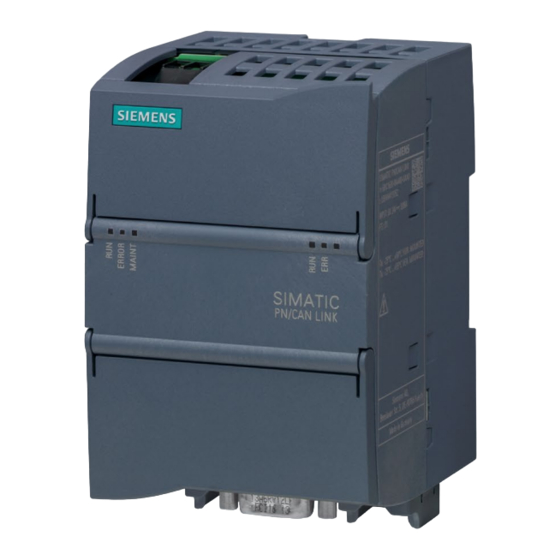
Figure 3-1 SIMATIC PN/CAN LINK The SIMATIC PN/CAN LINK is a communication gateway and allows for the connection of SIMATIC controllers to the CAN fieldbus over PROFINET. This connection enables the exchange of information and data between PROFINET and CAN. - Page 16 ● All PDO transmission rates specified in the CiA301 standard are supported. ● Segmented SDO data transmission is supported. ● SYNC function as producer (sender) as well as consumer (receiver) ● "Heartbeat" function ● "Node guarding" function ● "EMCY" (Emergency) function SIMATIC PN/CAN LINK Operating Instructions, 03/2018, A5E39895388-AB...
- Page 17 ● The PN/CAN LINK can forward data from received CAN messages to the S7 controller as PROFINET input data. ● Der PN/CAN LINK can send CAN messages with PROFINET output data of the S7 controller. SIMATIC PN/CAN LINK Operating Instructions, 03/2018, A5E39895388-AB...
-
Page 18: System Configuration
IO image. Acyclic communication takes place by means of "Read/write data record" services. An external power supply unit with 24 V DC or the 24 V power supply of the SIMATIC S7 system provides the power supply of the PN/CAN LINK. -
Page 19: System Requirements
System overview 3.3 System requirements System requirements System requirements ● PN/CAN LINK ● Controller: SIMATIC S7-1200, SIMATIC S7-1500, SIMATIC ET 200SP and SIMATIC OpenController are supported. ● 24 V voltage supply ● CAN bus ● PROFINET bus ● Windows PC (for configuring, commissioning and diagnostics) ●... -
Page 20: Design
PN/CAN LINK design See also 24 V DC power supply (Page 68) Operating state of the PN/CAN LINK / PROFINET diagnostics (Page 95) Connecting PROFINET (Page 70) Connecting the CAN bus (Page 71) SIMATIC PN/CAN LINK Operating Instructions, 03/2018, A5E39895388-AB... -
Page 21: Functions
The following overview diagram shows the correlations in the communication between CAN and PROFINET. Only available in Manager mode Only available in Slave mode Figure 4-1 PN/CAN LINK principle of communication with CANopen SIMATIC PN/CAN LINK Operating Instructions, 03/2018, A5E39895388-AB... -
Page 22: Object Dictionary
The following actions are being executed in the process: ● The default value is written to the OD. ● The information whether the OD entry has been written by the CANopen side once before is reset. SIMATIC PN/CAN LINK Operating Instructions, 03/2018, A5E39895388-AB... -
Page 23: Process Data Objects (Pdo)
"SYNC". Event-controlled transmit-PDOs with transmission type 255 (device-profile specific / and application-profile specific) are also transmitted during transition to the NMT state "Opera- tional". SIMATIC PN/CAN LINK Operating Instructions, 03/2018, A5E39895388-AB... -
Page 24: Service Data Objects (Sdo)
Is also transmitted when the NMT Manager tries to set the PN/CAN LINK to "Operational" state while the desired state transmitted in the cyclic data from the S7 controller is still "OFF". The EMCY messages always use the default COB ID intended for this purpose. SIMATIC PN/CAN LINK Operating Instructions, 03/2018, A5E39895388-AB... -
Page 25: Heartbeat / Node Guarding
COB ID is 0x80 in "CANopen Manager" mode. Note The SYNC function only has an effect on the CANopen side. It is not used to synchronize the data transmission on the CANopen side and the PROFINET side. SIMATIC PN/CAN LINK Operating Instructions, 03/2018, A5E39895388-AB... -
Page 26: Data Exchange Between Controller And Pn/Can Link
OD or before the process data read from the OD are sent to the S7 controller. The following table provides an overview of the data types supported by the PN/CAN LINK and their conversion. SIMATIC PN/CAN LINK Operating Instructions, 03/2018, A5E39895388-AB... -
Page 27: Canopen Manager
CiA standard CiA 302 Part 2. ● Configuration Manager: The PN/CAN LINK configures the CANopen slaves during the boot-up procedure by means of SDO write access. SIMATIC PN/CAN LINK Operating Instructions, 03/2018, A5E39895388-AB... -
Page 28: State Model
"CiA 302 Part 2" and configures the CANopen slaves with SDO. The PN/CAN LINK has the NMT state "Pre-Operational". The NMT state of the slaves connected via CANopen is "Pre- Operational" after booting. SIMATIC PN/CAN LINK Operating Instructions, 03/2018, A5E39895388-AB... - Page 29 (NMT Master error behavior is "Restart of the PN/CAN LINK"). Reset bit contained in the cyclic data from the S7 controller • Reconfiguration by the S7 controller • Error during boot-up (except heartbeat/node-guarding errors) • SIMATIC PN/CAN LINK Operating Instructions, 03/2018, A5E39895388-AB...
-
Page 30: Control And Status Information
An NMT command is sent instead to each fully booted slave individually. As soon as the other slaves are completely boot- ed, they are also switched to "Operational" with an NMT command. SIMATIC PN/CAN LINK Operating Instructions, 03/2018, A5E39895388-AB... - Page 31 LINK state CAN network "Pre-Operational" CAN network "Operational" CAN network "Stopped" Reserved If this state is being signaled con- tinuously, bit 2 in the control byte must be set to "1". 5…7 Reserved SIMATIC PN/CAN LINK Operating Instructions, 03/2018, A5E39895388-AB...
- Page 32 For values made up of multiple bits, the first bit is the MSB and the last bit is the LSB. Example: Bit 1 ... 0 = "2" means that bit 0 = "0" and bit 1 = "1". SIMATIC PN/CAN LINK Operating Instructions, 03/2018, A5E39895388-AB...
-
Page 33: Acyclic Data Exchange Between Controller And Pn/Can Link
PN/CAN LINK returns information that SDO access has not yet finished (status code = "Busy"). A maximum of 128 bytes are transmitted during an SDO access. SIMATIC PN/CAN LINK Operating Instructions, 03/2018, A5E39895388-AB... - Page 34 DF80C200 Communication channel (data record index) is already "busy". The PN/CAN LINK first expects a RDREC before it permits a new WRREC. When an error is recognized, SDO access is not even triggered. SIMATIC PN/CAN LINK Operating Instructions, 03/2018, A5E39895388-AB...
- Page 35 Incorrect data record index (not 0x200 to 0x20F) DE80B500 No completely and validly configured PROFINET connection (Application Relation) is established DE80A900 PN/CAN LINK is not CANopen Manager DE80C300 No previous successful WRREC DE80B700 Read buffer too small SIMATIC PN/CAN LINK Operating Instructions, 03/2018, A5E39895388-AB...
-
Page 36: Monitoring Functions
Node guarding A node guarding monitoring can be configured. The parameters required for this purpose "Monitoring time" and "Repetition factor" can be set. The PN/CAN LINK can be both a transmitter and a receiver. SIMATIC PN/CAN LINK Operating Instructions, 03/2018, A5E39895388-AB... -
Page 37: Canopen Slave
OD of the PN/CAN LINK during boot-up by the CANopen Manager responsible for the CANopen network via SDOs. Note Retentive storage in the PN/CAN LINK of the configuration received from a CANopen Manager in "CANopen Slave" mode is not supported. SIMATIC PN/CAN LINK Operating Instructions, 03/2018, A5E39895388-AB... -
Page 38: Object Dictionary
TX-PDO Mapping parameters 2xxxh Entries for the process data to be exchanged with the S7 controller. Entries for input data, that is data that comes from the S7 control- ler, are "Read Only" in CANopen. SIMATIC PN/CAN LINK Operating Instructions, 03/2018, A5E39895388-AB... -
Page 39: State Model
The state model in "CANopen Slave" mode is based on the NMT state model described in the CiA standard "CiA 301". The figure below shows the states of the PN/CAN LINK in "CANopen Slave" mode. Figure 4-3 State model CANopen Slave SIMATIC PN/CAN LINK Operating Instructions, 03/2018, A5E39895388-AB... - Page 40 OD 1029h was configured accordingly. Triggered by an NMT command from the CANopen Manager. Triggered by an NMT command from the CANopen Manager or by a communica- tion error when OD 1029h was configured accordingly. SIMATIC PN/CAN LINK Operating Instructions, 03/2018, A5E39895388-AB...
-
Page 41: Control And Status Information
"Operational", the PN/CAN LINK changes to the state "Pre-Operational". Commands from the NMT master to change to the "Operational" state are ignored. The PN/CAN LINK can be switched by the NMT master via NMT command to the "Operational" state. SIMATIC PN/CAN LINK Operating Instructions, 03/2018, A5E39895388-AB... - Page 42 PDO since the last reset. All receive OD entries have been updated at least once by a PDO or SDO since the last reset. SIMATIC PN/CAN LINK Operating Instructions, 03/2018, A5E39895388-AB...
-
Page 43: Monitoring Functions
The following error responses are supported: Subindex Description value Change to the "Pre-Operational" state only when the current state is "Operational" Current state is retained, that is no response Change to "Stopped" state SIMATIC PN/CAN LINK Operating Instructions, 03/2018, A5E39895388-AB... -
Page 44: Response To Errors
Bit is set in "any error situation", according to CiA standard "CiA 301", which means when a specific error bit is set and for errors that are not mapped to specific error bits. SIMATIC PN/CAN LINK Operating Instructions, 03/2018, A5E39895388-AB... -
Page 45: Can Transparent
PN/CAN LINK state "ON" In this state the PN/CAN LINK participates in the CAN bus communication, that is it transmits and receives CAN frames unless the CAN controller is in Bus Off state. SIMATIC PN/CAN LINK Operating Instructions, 03/2018, A5E39895388-AB... - Page 46 The PN/CAN LINK receives the necessary configuration data from the S7 controller. For the "receive message modules" the input data is preas- signed according to the parameter assignment. PN/CAN LINK state is "OFF". SIMATIC PN/CAN LINK Operating Instructions, 03/2018, A5E39895388-AB...
-
Page 47: Can Messages
The sending and receiving of CAN messages from the S7 user program is possible using transmit and receive proxy modules. See: Cyclic data exchange between controller and PN/CAN LINK for programmed CAN messages (Page 48) SIMATIC PN/CAN LINK Operating Instructions, 03/2018, A5E39895388-AB... -
Page 48: Control And Status Information
This is the normal state. Everything is okay. 1) The error counters customary in CAN and the associated thresholds are internal functions that are not visible to the user. SIMATIC PN/CAN LINK Operating Instructions, 03/2018, A5E39895388-AB... -
Page 49: Cyclic Data Exchange Between Controller And Pn/Can Link For Configured Can Messages
"endianness" of PROFINET and CAN. PROFINET uses "Big Endian", CAN usually uses "Little Endian". In the case of programmed CAN messages, however, the order of the data bytes is not changed. SIMATIC PN/CAN LINK Operating Instructions, 03/2018, A5E39895388-AB... -
Page 50: Cyclic Data Exchange Between Controller And Pn/Can Link For Programmed Can Messages
Example of receive proxy module: Because each receive proxy module has its own "receive filter list", you can use multiple proxy modules to pre-filter messages by CAN ID, for example, one receive proxy for "commands" only and one receive proxy for "status messages". SIMATIC PN/CAN LINK Operating Instructions, 03/2018, A5E39895388-AB... - Page 51 For values made up of multiple bits, the first bit is the MSB and the last bit is the LSB. Example: Byte.Bit 3.0 ... 4.6 = 2 means: Byte 3 bit 0 = "0", byte 4 bit 7 = "1" and byte 4 bit 6 = "0". SIMATIC PN/CAN LINK Operating Instructions, 03/2018, A5E39895388-AB...
- Page 52 For 29-bit message IDs byte 1 bit 4 is the most significant bit and byte 4 bit 0 the least significant bit. 5-12 Data bytes In the order in which they are going to be sent SIMATIC PN/CAN LINK Operating Instructions, 03/2018, A5E39895388-AB...
- Page 53 ● Instruct the PN/CAN LINK to ignore the receive filter As a result, all CAN messages are copied to the receive buffer. ● Instruct the PN/CAN LINK to delete all CAN messages in the receive buffer SIMATIC PN/CAN LINK Operating Instructions, 03/2018, A5E39895388-AB...
- Page 54 The S7 controller must then set the receive enable bit to "0" and must wait until the PN/CAN LINK has also set the "Message exists" bit to "0". Only then may the S7 controller set the receive enable bit to "1" again. SIMATIC PN/CAN LINK Operating Instructions, 03/2018, A5E39895388-AB...
- Page 55 In the order in which they were received. Only the corresponding "Number of data bytes in the received CAN message" may be evaluated. Note: May only be evaluated when the transfer bit is "1" SIMATIC PN/CAN LINK Operating Instructions, 03/2018, A5E39895388-AB...
- Page 56 16 filters with 4 bytes each for Criterion and Mask are permitted. If the number of written bytes is ≥ 128, the write access (WRREC) is rejected with PROFINET error code 0xDF80B100 and the filter remains unchanged. SIMATIC PN/CAN LINK Operating Instructions, 03/2018, A5E39895388-AB...
- Page 57 If less than 8 bytes are written or if bit 31 = "1" is true for "Criterion" for all filters, the receive proxy has "no valid receive filter". That is signaled in the corresponding bit in the input data for the S7 controller. SIMATIC PN/CAN LINK Operating Instructions, 03/2018, A5E39895388-AB...
-
Page 58: Response To Errors
In "CAN transparent" mode the PN/CAN LINK signals its state by means of the fieldbus LEDs on the front of the housing. The meaning of the LEDs is described in section Operating state of the PN/CAN LINK / PROFINET diagnostics (Page 95). SIMATIC PN/CAN LINK Operating Instructions, 03/2018, A5E39895388-AB... -
Page 59: Application Planning
● Proper grounding and wiring of the PN/CAN LINK is important for optimal operation and for sufficient immunity of your system and your application. SIMATIC PN/CAN LINK Operating Instructions, 03/2018, A5E39895388-AB... -
Page 60: Installation Location
● For horizontal mounting position: At least 35 mm above and below the PN/CAN LINK ● For vertical mounting position: At least 35 mm to the left and right of the PN/CAN LINK SIMATIC PN/CAN LINK Operating Instructions, 03/2018, A5E39895388-AB... - Page 61 PN/CAN LINK must be protected by an enclosure with the corresponding degree of protection. IP54 is a protection class that is generally used for electronic systems in heavily polluted environments and may be suitable for your application. SIMATIC PN/CAN LINK Operating Instructions, 03/2018, A5E39895388-AB...
-
Page 62: Transportation
20 K per hour are not permitted. Storage The devices must be stored in clean and dry rooms, preferably in their original packaging. The storage temperature must be between -40 °C and +70 °C. SIMATIC PN/CAN LINK Operating Instructions, 03/2018, A5E39895388-AB... -
Page 63: Scope Of Delivery
3. Check the device for transport damage by visual inspection. NOTICE Damage to the system Damaged parts can result in damage to the system. Do not use devices that show evidence of damage! SIMATIC PN/CAN LINK Operating Instructions, 03/2018, A5E39895388-AB... - Page 64 Application planning 5.5 Scope of delivery SIMATIC PN/CAN LINK Operating Instructions, 03/2018, A5E39895388-AB...
-
Page 65: Mounting/Extending
) must always be in the default positions set at the factory. Otherwise the mounting sliders may warp if they are exposed to hot and humid ambient conditions for a long time. SIMATIC PN/CAN LINK Operating Instructions, 03/2018, A5E39895388-AB... - Page 66 Fasten the screw with the corresponding torque until the spring lock washer is pressed flat. Do not fasten the screws with excessive torque. Figure 6-2 Control panel mounting of the PN/CAN LINK SIMATIC PN/CAN LINK Operating Instructions, 03/2018, A5E39895388-AB...
-
Page 67: Connecting
• Voltages > 60 V DC or 30 V AC are present in the control cabinet. Therefore appropriate safety precautions must be taken to prevent contact during commissioning and maintenance work. • Before working on the PN/CAN LINK or the connected components, ensure the system is disconnected. SIMATIC PN/CAN LINK Operating Instructions, 03/2018, A5E39895388-AB... - Page 68 7.1 Safety instructions and guidelines Wiring guidelines When wiring the PN/CAN LINK, observe the wiring guidelines of your automation system (e.g. SIMATIC S7-1200, SIMATIC S7-1500, SIMATIC ET 200SP). Also observe the installation instructions and configuration guidelines for routing of the PROFINET cables.
-
Page 69: Potential Ratios
PROFINET cables to a shield rail. The shields of the CAN interface are capacitively decoupled from the shields of the PROFINET interface to prevent compensating currents over the cable shields. Figure 7-1 Block diagram shielding SIMATIC PN/CAN LINK Operating Instructions, 03/2018, A5E39895388-AB... -
Page 70: Dc Power Supply
The connection of the external 24 V power supply and the functional earth connection takes place via a 3-pin screw-type terminal. It is located below the top housing cover (see Design (Page 18)). A suitable power supply is, for example, SIMATIC S7-1200 Power Supply PM1207 (6EP1332-1SH71). Safety information... -
Page 71: Connecting The Functional Ground
EMC-compliant functional grounding • Use as short a stranded-wire conductor as possible with a large cross section. • Compliance with the technical specifications of the device is only assured with a correct functional ground connection. SIMATIC PN/CAN LINK Operating Instructions, 03/2018, A5E39895388-AB... -
Page 72: Connecting Profinet
Ethernet connectors are installed on the bottom part of the housing in the delivery state. These retaining collars are intended for the Siemens FastConnect connectors. NOTICE Make sure you observe the minimum bending radius of the Ethernet cable; otherwise the shield effect of the cable shield may be impaired. -
Page 73: Connecting The Can Bus
The connection CAN Ground to ground is necessary to ensure EMC stability. The common return (CAN_GND) may only be connected in one place to the ground potential in the CAN network. NOTICE EMC stability is only guaranteed with shielded CAN cables. SIMATIC PN/CAN LINK Operating Instructions, 03/2018, A5E39895388-AB... - Page 74 Connecting 7.6 Connecting the CAN bus SIMATIC PN/CAN LINK Operating Instructions, 03/2018, A5E39895388-AB...
-
Page 75: Commissioning
Commissioning the PN/CAN LINK Prerequisites ● The PN/CAN LINK is installed and connected to a SIMATIC S7-CPU via PROFINET. ● The CAN bus is connected to the PN/CAN LINK. ● The PN/CAN LINK and all other components are wired and connected. - Page 76 Commissioning 8.1 Commissioning the PN/CAN LINK SIMATIC PN/CAN LINK Operating Instructions, 03/2018, A5E39895388-AB...
-
Page 77: Configuring / Programming
8. Define the corresponding receive PDOs and transmit PDOs in the manager module. 9. If necessary, make additional settings, such as heartbeat, node guarding and SYNC. 10.Check and compile the configuration. SIMATIC PN/CAN LINK Operating Instructions, 03/2018, A5E39895388-AB... -
Page 78: Configuration View In The Tia Portal
CPU and PN/CAN LINK are connected in the "Devices & networks" window with a green ② PN line ③ 3. Assign the parameters of the PROFINET interface of the PN/CAN LINK according to the configuration of your PROFINET network. Figure 9-1 TIA Portal: Devices & networks SIMATIC PN/CAN LINK Operating Instructions, 03/2018, A5E39895388-AB... - Page 79 All settings for the CANopen Manager module of the PN/CAN LINK are made in slot 1. Setting the communication parameters Set the bus-specific parameters, for example, node ID and transmission rate. Figure 9-3 Communication SIMATIC PN/CAN LINK Operating Instructions, 03/2018, A5E39895388-AB...
- Page 80 (e.g. corrections), you must first delete the node and then create once again. 3. Check the object dictionary (OD) of the CAN device for completeness and correctness. In the following, we assume that the OD can be used without changes. SIMATIC PN/CAN LINK Operating Instructions, 03/2018, A5E39895388-AB...
- Page 81 OD entry. Figure 9-6 Object dictionary index definition ② 3. Create the subindices associated with the OD index. To create additional subindex entries, double-click "Add". SIMATIC PN/CAN LINK Operating Instructions, 03/2018, A5E39895388-AB...
- Page 82 4. Assign transmit data to the transmit PDO. To assign the data, select the data that is to be transmitted in the transmit PDO from the ③ "All usable OD entries" table with the buttons in the "Use" column SIMATIC PN/CAN LINK Operating Instructions, 03/2018, A5E39895388-AB...
- Page 83 S7 program is set correctly. Checking data consistency You can check the consistency of the assignments for the receive data and transmit data as well as the data types used with a compilation. SIMATIC PN/CAN LINK Operating Instructions, 03/2018, A5E39895388-AB...
-
Page 84: Configuring Canopen Slave
5. Set bus-specific parameters for the "CANopen Slave" module: Node ID and transmission rate 6. Create OD entries for the process data to be exchanged between the S7 controller and the CANopen network. 7. Check and compile the configuration. 8. Export the EDS file. SIMATIC PN/CAN LINK Operating Instructions, 03/2018, A5E39895388-AB... -
Page 85: Configuring In The Tia Portal
CPU and PN/CAN LINK are connected in the "Devices & networks" window with a green ② PN line ③ 3. Assign the parameters of the PROFINET interface of the PN/CAN LINK according to the configuration of your PROFINET network. Figure 9-8 TIA Portal: Devices & networks SIMATIC PN/CAN LINK Operating Instructions, 03/2018, A5E39895388-AB... - Page 86 All settings for the CANopen Slave module of the PN/CAN LINK are made in slot 1. Setting the communication parameters Set the bus-specific parameters for the CANopen Slave module: Node ID and transmission rate. Figure 9-10 Setting the communication parameters SIMATIC PN/CAN LINK Operating Instructions, 03/2018, A5E39895388-AB...
- Page 87 Repeat the above steps until all desired transmit data has been created in the OD of the Manager. Note You can create a maximum of 100 OD entries. This maximum number is independent of the distribution of entries between the transmit data OD and receive data OD. SIMATIC PN/CAN LINK Operating Instructions, 03/2018, A5E39895388-AB...
- Page 88 S7 user program. This control bit is cyclically transmitted from the S7 controller to the PN/CAN LINK as part of the IO data. However, the actual state transition must be triggered by the current NMT master. SIMATIC PN/CAN LINK Operating Instructions, 03/2018, A5E39895388-AB...
-
Page 89: Configuring Can Transparent
PN/CAN LINK appears in the "Devices & networks" window. 2. Connect the CPU and PN/CAN LINK by means of a PROFINET connection. CPU and PN/CAN LINK are connected in the "Devices & networks" window with a green ② PN line SIMATIC PN/CAN LINK Operating Instructions, 03/2018, A5E39895388-AB... - Page 90 1. Select the "CAN transparent" operating mode. After selection of the operating mode the parameters associated with the selected mode can be set. All settings for the "CAN transparent" module of the PN/CAN LINK are made in slot 1. SIMATIC PN/CAN LINK Operating Instructions, 03/2018, A5E39895388-AB...
- Page 91 1. Double-click "Transmit message" or "Receive message" in the HW catalog. The corresponding message type is placed as a submodule in the "CAN transparent" module. ② 2. Create the necessary message definitions Figure 9-17 Transmit and receive messages SIMATIC PN/CAN LINK Operating Instructions, 03/2018, A5E39895388-AB...
- Page 92 PN/CAN LINK that the control information transmitted here from the S7 program is set correctly. Checking data consistency You can check the consistency of the assignments for the receive data and transmit data as well as the data types used with a compilation. SIMATIC PN/CAN LINK Operating Instructions, 03/2018, A5E39895388-AB...
-
Page 93: Programming
As of TIA Portal V15, it is possible to switch automatic tag generation for I/O objects on and off. Make sure that automatic tag generation is activated. The setting option is available under "General > Generate PLC tags" after you have set the CAN operating mode. SIMATIC PN/CAN LINK Operating Instructions, 03/2018, A5E39895388-AB... - Page 94 > Prefix ByteAdr Integer 64 * < >.<Subindex name> LInt %I< >.0 Prefix ByteAdr Real 32 < >.<Subindex name> Real %ID< > Prefix ByteAdr Real 64 * < >.<Subindex name> LReal %I< >.0 SIMATIC PN/CAN LINK Operating Instructions, 03/2018, A5E39895388-AB...
- Page 95 I/Q: Input/output bit address IB/QB: Input/output byte address ID/QD: Input/output double word address * The S7-1200 controller does not support 64-bit data types, so the generated tags cannot be used for the S7-1200. SIMATIC PN/CAN LINK Operating Instructions, 03/2018, A5E39895388-AB...
- Page 96 Configuring / programming 9.4 Programming SIMATIC PN/CAN LINK Operating Instructions, 03/2018, A5E39895388-AB...
-
Page 97: Diagnostics
While the firmware is written to the flash • memory. Flashes LEDs are flashing 3-second intervals • (triggered by TIA Flashes Flashes Portal) 1) The MAINT LED currently has no meaning. x: LED state is irrelevant SIMATIC PN/CAN LINK Operating Instructions, 03/2018, A5E39895388-AB... - Page 98 Indicates whether there is a physical connection on the Ethernet level. Connection exists No connection exists Rx/Tx Indicates whether a package is being sent or received PN/CAN LINK sends or receives a package No package is sent or received SIMATIC PN/CAN LINK Operating Instructions, 03/2018, A5E39895388-AB...
-
Page 99: Connection Status Can Bus In The Two Canopen Operating Modes
At least one error counter in the CAN controller has reached its warning threshold. One-time brief flashing A heartbeat or node guarding error has occurred. Two-time brief flashing The CAN controller is in "Bus-Off" state. SIMATIC PN/CAN LINK Operating Instructions, 03/2018, A5E39895388-AB... -
Page 100: Connection Status Can Bus In "Can Transparent" Operating Mode
Table 10- 4 Behavior of the ERR LED ERR LED Meaning No error on the CAN bus The CAN controller is in "Error passive" state. One-time brief flashing The CAN controller is in "Bus-Off" state. SIMATIC PN/CAN LINK Operating Instructions, 03/2018, A5E39895388-AB... -
Page 101: Diagnostic Messages To The S7 Controller
● Events that cause a pending diagnostic message to be withdrawn ● The associated component The diagnostic messages including description are listed in the section Diagnostic messages (Page 102). The descriptions also include instructions and information on error correction. SIMATIC PN/CAN LINK Operating Instructions, 03/2018, A5E39895388-AB... - Page 102 Cause of cessfully ing slave error, if module known Receipt of an EMCY message Diagnostic information was Correspond- Error codes of transmitted to the S7 controller ing slave the EMCY via PROFINET module message SIMATIC PN/CAN LINK Operating Instructions, 03/2018, A5E39895388-AB...
- Page 103 Diagnostic information was PN/CAN LINK CAN packets transmitted to the S7 controller via PROFINET Receipt of a CAN packet with Diagnostic information was Corresponding input module incorrect length transmitted to the S7 controller via PROFINET SIMATIC PN/CAN LINK Operating Instructions, 03/2018, A5E39895388-AB...
-
Page 104: Diagnostic Messages
Slave, CANopen Slave tion error detected. Check for communication problems caused by EMI. If Transparent CAN transparent these can be excluded, there may be a hardware fault and the module must be replaced. SIMATIC PN/CAN LINK Operating Instructions, 03/2018, A5E39895388-AB... - Page 105 (OD 1018.3) Check whether the correct device is connected and the right EDS file was loaded. If the version number is 0, it could not be read by the device. SIMATIC PN/CAN LINK Operating Instructions, 03/2018, A5E39895388-AB...
- Page 106 Internal software error An internal error was detected and is now being signaled Slave, - ({1:x}). after restart of the module. Transparent The error message disappears when you restart the mod- ule again. SIMATIC PN/CAN LINK Operating Instructions, 03/2018, A5E39895388-AB...
-
Page 107: Maintenance And Service
PN/CAN LINK run-up. This can result in critical plant states. 11.2 Replacing the PN/CAN LINK Below you will find a description of the basic steps required for replacing the PN/CAN LINK. Preparations De-energize the S7 configuration including PN/CAN LINK. SIMATIC PN/CAN LINK Operating Instructions, 03/2018, A5E39895388-AB... -
Page 108: Recycling And Disposal
There is no provision for returning the device to Siemens. For further questions regarding disposal and recycling, please contact your local Siemens contact. You will find the contact details in our database on the Internet at: http://www.automation.siemens.com/partner SIMATIC PN/CAN LINK... -
Page 109: Technical Specifications
Technical specifications of the PN/CAN LINK Technical specifications PN/CAN LINK Article number 6BK1620-0AA00-0AA0 General information Product type designation SIMATIC PN/CAN LINK Firmware version FW update possible • Vendor identification (VendorID) ID 09 00 00 53h acc. to CiA Engineering with... - Page 110 Interface type PROFINET Physics Ethernet, 2-port switch, 2*RJ45 Isolated Yes; 1 500 V AC or 2 250 V DC Interface types Number of ports • integrated switch • Functionality PROFINET IO Device • SIMATIC PN/CAN LINK Operating Instructions, 03/2018, A5E39895388-AB...
- Page 111 Ambient temperature during stor- age/transportation -40 °C min. • 85 °C max. • Relative humidity 95 % Operation, max. • Dimensions Width 70 mm Height 112 mm Depth 75 mm Weights Weight, approx. 212 g SIMATIC PN/CAN LINK Operating Instructions, 03/2018, A5E39895388-AB...
-
Page 112: Dimension Drawing
Technical specifications 12.2 Dimension drawing 12.2 Dimension drawing Dimension drawings of the PN/CAN LINK Figure 12-1 Dimension drawing PN/CAN LINK SIMATIC PN/CAN LINK Operating Instructions, 03/2018, A5E39895388-AB... -
Page 113: Appendix
You can check which of the following approvals have been granted for your product by the markings on the type plate. CE marking The SIMATIC PN/CAN LINK device conforms to the requirements and safety objectives of the EC Directives listed below. EMC Directive 2014/30/EU The product is designed for operation in residential and industrial areas. -
Page 114: Contact Address
Licenses Use of open source software (OSS) Open-source software is used in the SIMATIC PN/CAN LINK product in unchanged form or in a form changed by us. License conditions and sources that have to be published are included on the CD supplied with the product. -
Page 115: Service & Support
You can contact the Technical Support experts in Germany at the following number: ● Phone: + 49 (0) 911 895 7222 ● The contact data for Technical Support in other countries can be found in the Siemens contact database (http://w3.siemens.com/aspa_app/). - Page 116 Appendix A.4 Service & Support SIMATIC PN/CAN LINK Operating Instructions, 03/2018, A5E39895388-AB...
-
Page 117: Glossary
SDO write access. CiA (CAN in Automation) International users' and manufacturers' group for the distribution and standardization of CAN Consumer The receiver of messages is referred to as consumer in a CAN network. SIMATIC PN/CAN LINK Operating Instructions, 03/2018, A5E39895388-AB... - Page 118 PROFINET (Process Field Network) is the open Industrial Ethernet standard of the PROFIBUS User Organization for automation. Process data object see PDO Producer The sender of messages is referred to as producer in a CAN network. SIMATIC PN/CAN LINK Operating Instructions, 03/2018, A5E39895388-AB...
- Page 119 SDO is a specification for a framework for uniform data access to all entries in the CANopen object dictionary. SIMATIC Controller The SIMATIC Controllers are available as Basic, Advanced, Distributed and Software controllers. The Basic Controller S7-1200 for small to medium-sized applications, the Advanced Controller S7-1500 for medium-sized and complex applications, the Distributed Controller ET 200SP for distributed applications and the Software Controller S7-1500 for PC- based applications.
- Page 120 Glossary SIMATIC PN/CAN LINK Operating Instructions, 03/2018, A5E39895388-AB...
-
Page 121: Index
Documentation, 7 Terminals for the 24 DC power supply, 68 HSP, 16, 43, 82, 87 Consumer, 41 Contact person for the database, 106 Control panel, 64 Control panel mounting, 63 Controller information, 39 SIMATIC PN/CAN LINK Operating Instructions, 03/2018, A5E39895388-AB... - Page 122 TIA Portal, 17, 73, 82 Design, 18 Trademark PN/CAN LINK states SIMATIC!, 7 Operational, 26 Pre-Operational, 26 Stopped, 26 Power supply, 16, 68 Producer, 41 Wiring guidelines, 66 PROFINET, 16 Connecting, 70 PROFINET diagnostics, 95 SIMATIC PN/CAN LINK Operating Instructions, 03/2018, A5E39895388-AB...
Need help?
Do you have a question about the Simatic and is the answer not in the manual?
Questions and answers