Table of Contents
Advertisement
Quick Links
Advertisement
Table of Contents

Subscribe to Our Youtube Channel
Related Manuals for D+H CPS-M1


Summary of Contents for D+H CPS-M1
- Page 1 CPS-M1 G 517002 0786 - CPD - 50680 EN 12101-10:2005 + Corr. 1:2007 Anerkennungs-Nr. conform approval-no. en Original instructions ..........Page ............2 99.827.31 1.4/06/18...
-
Page 2: Table Of Contents
Safety in the building is not only provided by the product. Safety is cre- Actuator module - AM-1-1-08-230-D4-D2..........6 ated above all by competence. All D+H service and sales partners are Power packs PS-S1-24-20 and PS-S1-24-40 ........6 certified and regularly trained SHEV specialist companies. They work Technical data.................. -
Page 3: Intended Use
• Combine lines and groups however you want • AdComNet bus system for seamless networking of the modules • Convenience functions for daily ventilation within the CPS-M and further D+H AdComNet SHEV control system • Only intended for installation indoors • Simple implementation of complex SHEV scenarios •... -
Page 4: Overview Of Components
31.702.00 31.702.20 31.702.30 31.702.26 31.702.36 31.702.16 RJ12 connecting cable (2x) CC-TP/TCSU-1000 (1 m) 63.502.63 CC-TP/TCSU-2000 (2 m) 63.502.64 Touch panel with bracket (optional) Temperature control sensor unit TP-C1-35-RJ12 TCSU1-RJ12 RJ12 socket 31.702.90 (Page 5) 31.702.70 4/36 CPS-M1 English 99.827.31 1.4/06/18... -
Page 5: Control Module - Cm-Bt1-D4-P2
SHEV buttons and 30 fire detectors per line (only • The cable is monitored for breaks and short circuits detectors approved by D+H may be used) via the terminal module EM-47K • Cables are monitored by the EM-L01 terminal module •... -
Page 6: Actuator Module - Am-1-1-08-230-D4-D2
• Module for connecting 230 V AC actuators • 1 group for connecting drives with a total maximum current of 8 A • D+H 230 V AC drives with SHEV fast mode (HS) are supported • The cable is monitored for breaks and short circuits via the terminal module EM 230 •... -
Page 7: Technical Data
We declare under our sole responsibility that the product described under "Technical Data" complies with the following directives: 2014/30/EU, 2014/35/EU, EU 305/2011 Technical documents stored at: D+H Mechatronic AG, D-22949 Ammersbek Dirk Dingfelder Maik Schmees Authorised Officer, Technical Director 04.07.2018 99.827.31 1.4/06/18... -
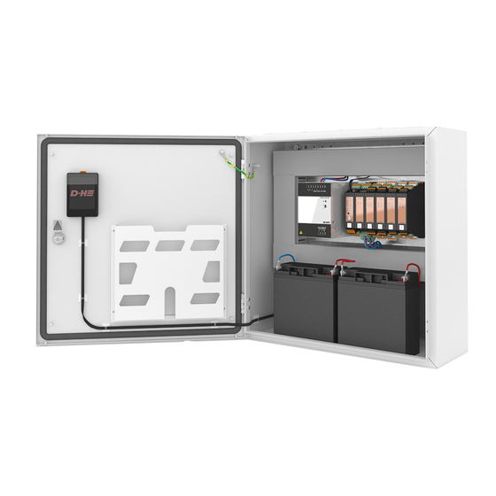
Page 8: Inner Structure Of Standard Control Panels
Inner structure of standard control panels CPS-M1-020-xxxx Fig.: CPS-M1-020-0202 Standard equipment 31.700.10 CPS-M1-020-0202 |CM|PSM|AM|TMA| 31.700.15 CPS-M1-020-0204 |CM|PSM|AM|AM|TMA| PS-S1-24-20 31.700.20 CPS-M1-020-0404 |CM|PSM|AM|AM|TMA|TMA| 31.700.25 CPS-M1-020-0606 |CM|PSM|AM|AM|AM|TMA|TMA|TMA| CPS-M1-040-xxxx CPS-M1-060-xxxx Fig.: CPS-M1-040-0204 Fig.: CPS-M1-060-0206 Standard equipment Standard equipment 31.700.30 CPS-M1-040-0204 |CM|PSM|AM|AM|TMA| 31.700.55 CPS-M1-060-0206 |CM|PSM|AM|AM|PSM|AM|TMA| 31.700.35 CPS-M1-040-0206 |CM|PSM|AM|AM|AM|TMA|... -
Page 9: Arrangement Of The Modules
PSM must not exceed the output current of the respective power supply unit. 2x Akku Type 6 PS-S1-24-40 2x Akku Type 6 PS-S1-24-40 Installation of the module sockets Removal of the module sockets 99.827.31 1.4/06/18 English CPS-M1 9/36... -
Page 10: General Instructions For Connection
SHEV opening Due to the variety available on the market, See cable lengths and cross sections no type designations are specified for these cables. Please contact your D+H Partner for 230 V AC 50 Hz this information. Separate power circuit. -
Page 11: Connection - Psm
Output: 24 V DC RJ12 PS-1-24-20/40 Input: 230 V AC, 50 Hz X5.1 X5.2 – – X6.1 Battery Battery TCSU1-RJ12 230 V AC, 50 Hz X6.2 Separate power circuit. Identify the fuse. Do not reverse L+N! Connect PE 99.827.31 1.4/06/18 English CPS-M1 11/36... -
Page 12: Connection - Cm
2 resistors (110 Ω). The resistors must be X6.5 X6.1 connected as far apart as possible. Connections that are not used also have to be terminated! Earth the shielding Freely configurable digital inputs once per segment. 12/36 CPS-M1 English 99.827.31 1.4/06/18... -
Page 13: Connection - Digital Inputs And Outputs On Cm, Am, Tma And Iom
The battery should be replaced at least every 10 years. Attention! Folgende Reihenfolge beachten: 1. Read out and save existing parameterization 2. Change battery. Battery type: Lithium cell CR1216 3. Read in parameterization again 99.827.31 1.4/06/18 English CPS-M1 13/36... -
Page 14: Connection - Iom
24 V DC Each max. 50 mA (programmable using SCS) 24 V DC X1.1 X1.5 X2.1 X2.5 < either > active plus X3.1 X3.5 active minus Digital inputs X4.5 X4.1 X5.5 X5.1 IOM-D1-1212 X6.5 X6.1 14/36 CPS-M1 English 99.827.31 1.4/06/18... -
Page 15: Connection - Brm
If the "None" configuration is selected, the last status is retained. X1.1 X1.4 X2.1 X2.4 X3.1 X3.4 X4.4 X4.1 X5.4 X5.1 BRM-1-COC-0006 X6.4 X6.1 99.827.31 1.4/06/18 English CPS-M1 15/36... -
Page 16: Connection - Am 24
0 to 28 V, active minus or plus / CLOSE LT 1 Connection – Vent buttons to AM 24 AM-1-2-10-24-D6-D2 X4.4 X4.1 X5.4 X5.1 X6.4 X6.1 LT 84-U (-SD) LT 84-U (-SD) Ventilation Ventilation button 1 button 2 16/36 CPS-M1 English 99.827.31 1.4/06/18... -
Page 17: Connection - Am 24 With Acb Drives
Connection – AM 24 with pole-changing drives Actuator group 1 Actuator group 2 Drives Drives Mot.a Mot.a Mot.b Mot.b ACB.a/HS ACB.a/HS X1.1 X1.4 Mot.a Mot.a X2.1 X2.4 Mot.b Mot.b ACB.a/HS ACB.a/HS X3.1 X3.4 AM-1-2-10-24-D6-D2 99.827.31 1.4/06/18 English CPS-M1 17/36... -
Page 18: Connection - Am 230
Connection – NSV 401 control and vent button to AM 230 AM-1-1-08-230-D4-D2 X4.5 X4.1 X5.4 X5.1 X6.4 X6.1 LT 84-U (-SD) NSV 401 Ventilation button Power System Battery low A.V.R active NSV 401 Battery-Mode Battery-Mode 18/36 CPS-M1 English 99.827.31 1.4/06/18... -
Page 19: Connection - Nsv 401 Power Supply And D+H Drives
Connection – NSV 401 power supply and D+H drives EM 230 NSV 401 L▲ L▼ Drives 1 2 3 4 5 6 7 8 9 L ▼ L ▲ X1.1 X1.2 before / vor / avant Battery Service - switch off the battery - Batterieschalter auf OFF schalten L ▼... -
Page 20: Connection - Tma
Freely configurable digital output 3.3, max. 50 mA X6.3 Reference potential (do not connect to P-) X6.2 DO 4.2 Freely configurable digital output 4.2, max. 50 mA X6.1 DO 4.3 Freely configurable digital output 4.3, max. 50 mA 20/36 CPS-M1 English 99.827.31 1.4/06/18... -
Page 21: Connection - Tma (2 Lines)
RT Line 1 RM line 1 RM line 2 RT 45 RT 45 SD-O 371 / FD-T 271 EM-L01 EM-L01 X1.1 X1.5 X2.1 X2.5 EM-L01 EM-L01 X3.1 X3.5 TMA-1-D4-D12 X4.5 X4.1 X5.5 X5.1 X6.5 X6.1 99.827.31 1.4/06/18 English CPS-M1 21/36... -
Page 22: Connection - Tma Parallel Connection Rt
RT line EM-L01 X1.1 X1.5 X2.1 X2.5 X3.1 X3.5 TMA-1-D4-D12 Connection – TMA to fire alarm system (FAS) Trigger from Operating contact X1.1 X1.5 Reset from (Configuration via SCS required) X2.1 X2.5 X3.1 X3.5 TMA-1-D4-D12 22/36 CPS-M1 English 99.827.31 1.4/06/18... -
Page 23: Description Of The Inputs And Outputs
The maximum output current of the supply is 10 A. The supply is permanently short-circuit resistant and the fuse used is self-resetting. ACN D+ / ACN D- AdComNet connection: used for interconnecting more than one CPS-M1 and for interconnecting with ACN-CM501, Shield ACN-IO501, ACN-BI501-USB and ACN-GW501-MRTU. -
Page 24: 230 V Ac Emergency Power Supply - Nsv 401
230 V AC Emergency power supply – NSV 401 Functions: • The NSV 401 is an emergency power supply for 230 V AC D+H SHEV systems. In combination with the AM 230, the NSV 401 supplies the connected SHEV drives with mains voltage. In case of power failure they are supplied with 230 V AC for 3 minutes (When the retriggering function is switched on after approx. -
Page 25: Schematic Design - Nsv 401
Recommended temperature +15 ... +25°C • Only intended for installation indoors Cooling Fan cooling • Only use unaltered D+H original parts Noise level < 45 dB Dimensions (W x H x D) 355 x 250 x 205 mm Batteries:... -
Page 26: Connection Overview - Nsv 401
L ▼ 230 V AC, 50 Hz L ▲ Separate power circuit. Identify the fuse. Do not reverse L+N! Connect PE NSV 401 AM-1-1-08-230-D4-D2 NSV 401 NSV 401 Power Battery low NSV 401 A.V.R active Battery-Mode 26/36 CPS-M1 English 99.827.31 1.4/06/18... -
Page 27: Connecting / Changing Batteries
Switch the power on again. (Mains fuse or separate switch for NSV supply.) Power Set the power switch back to ON. The battery monitor must light up green Battery OK 99.827.31 1.4/06/18 English CPS-M1 27/36... -
Page 28: Commissioning And Configuration With The Scs Software
Commissioning and configuration with the SCS software The D+H Service and Configuration Suite (SCS) is used for commissioning and programming. Functions programmable via SCS: AM 24: AM 230: Alarm with HS ATTENTION! This function must only be used in conjunction with corresponding TMA: D+H high speed drives. -
Page 29: Standard Configurations
Screenshots from SCS-Tool for the standard pre-configurated actuator modules and trigger modules. Standard classification CPS-M1-XXX-XXXX Trigger Module / Trigger Line >> Actuator Module / Actuator Group All ventilation button inputs are pre-configured with the same module actuator group with the same color. - Page 30 Standard configurations (continuation) Standard classification CPS-M1-XXX-XXXX Trigger Module / Trigger Line >> Actuator Module / Actuator Group All ventilation button inputs are pre-configured with the same module actuator group with the same color. Trigger Module 1 Trigger Line1 >> Actuator Module 1 Actuator Group 1+2, 31.700.85...
-
Page 31: Description Of The Software Functions
With this the state of the potential-free contact can be defined, which is to be taken (bistable, BRM) in case of a failure of the mains and battery supply. If the "None" configuration is selected, the last status is retained. 99.827.31 1.4/06/18 English CPS-M1 31/36... -
Page 32: Operation - Touch Panel (Optional)
• Status display of the inputs and outputs AM 230 - Actuator module • Display of the module status • Status display of the group • Status display of the inputs and outputs 32/36 CPS-M1 English 99.827.31 1.4/06/18... -
Page 33: Operation - Daily Ventilation
LT 84-U-W Operation - SHEV RT 45: Operation OK Safety system, protects human life and real property value! ALARM Function check once a year by a Fault specialist company authorised by the manufacturer. Alarm RESET 99.827.31 1.4/06/18 English CPS-M1 33/36... -
Page 34: Operation - Trigger On Alarm
Operation - Trigger on alarm Manual opening with smoke vent button RT 45 RAUCHABZUG CPS-M1 (TMA) Automatic opening with fire detector RT 45 CPS-M1 (TMA) Automatic opening through external control (e.g. central fire alarm) RT 45 External control CPS-M1 (TMA) -
Page 35: Warranty
• Logging the proper completion of maintenance and • Labelling in accordance with requirements Only original D+H spare parts may be used. Repairs are carried out by D+H exclusively. Wipe off dirt with a dry, soft cloth. Do not use any detergents or solvents. - Page 36 D+H Mechatronic AG Georg-Sasse-Str. 28-32 22949 Ammersbek, Germany Tel.: +4940-605 65 239 Fax: +4940-605 65 254 E-Mail: info@dh-partner.com www.dh-partner.com Subject to technical modifications. © 2016 D+H Mechatronic AG, Ammersbek 99.827.31 1.4/06/18...
Need help?
Do you have a question about the CPS-M1 and is the answer not in the manual?
Questions and answers