Table of Contents
Advertisement
Quick Links
172-65185A-08 (MC-COSR Multi-control Valve) 20 November 2014
ISO 9001/ ISO 14001
Manufacturer
Kakogawa, Japan
is approved by LRQA LTD. to ISO
9001/14001
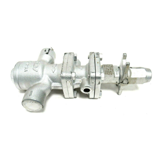
High-precision Multi-control Valve for Steam
MC-COSR-3/MC-COSR-16
Actuator: MC-GA2
Manufacturer
881 Nagasuna, Noguchi, Kakogawa, Hyogo, 675-8511 Japan
Tel: [81]-(0)79-422-1122 Fax: [81]-(0)79-422-0112
Copyright © 2014 by TLV Co., Ltd. All rights reserved
Advertisement
Table of Contents

Related Manuals for TLV MC-COSR-3


Summary of Contents for TLV MC-COSR-3
- Page 1 Kakogawa, Japan is approved by LRQA LTD. to ISO 9001/14001 High-precision Multi-control Valve for Steam MC-COSR-3/MC-COSR-16 Actuator: MC-GA2 Manufacturer 881 Nagasuna, Noguchi, Kakogawa, Hyogo, 675-8511 Japan Tel: [81]-(0)79-422-1122 Fax: [81]-(0)79-422-0112 Copyright © 2014 by TLV Co., Ltd. All rights reserved...
-
Page 2: Table Of Contents
MC-COSR, provides accurate pressure control (MC-COSR-3, MC-COSR-16) and temperature control (MC- COSR-16) when combined with the SC-F70 digital indicator controller or the SP-F70 programmable indicator controller. -
Page 3: Safety Considerations
The three types of cautionary items above are very important for safety: be sure to observe all of them as they relate to installation, use, maintenance and repair. Furthermore, TLV accepts no responsibility for any accidents or damage occurring as a result of failure to observe these precautions. - Page 4 Be sure to use only the recommended components when CAUTION repairing the product, and NEVER attempt to modify the product in any way. Failure to observe these precautions may result in damage to the product and burns or other injury due to malfunction or the discharge of fluids.
-
Page 5: Specifications
Specifications Install properly and DO NOT use this product outside the recommended CAUTION operating pressure, temperature and other specification ranges. Improper use may result in such hazards as damage to the product or malfunctions which may lead to serious accidents. Local regulations may restrict the use of this product to below the conditions quoted. - Page 6 70.8 (DIN) 13.3 20.6 31.9 50.8 72.9 Acceptable Operating Range Model MC-COSR-3 MC-COSR-16 Primary Pressure 0.1 – 0.3 MPaG 0.2 – 1.6 MPaG Range (15 – 45 psig) (30 – 250 psig) Within 10 – 84% of the primary pressure...
-
Page 7: Correct Usage Of The Mc-Cosr Multi-Control Valve
Correct Usage of the MC-COSR Multi-control Valve Install properly and DO NOT use this product outside the recommended CAUTION operating pressure, temperature and other specification ranges. Improper use may result in such hazards as damage to the product or malfunctions which may lead to serious accidents. Local regulations may restrict the use of this product to below the conditions quoted. - Page 8 4. Recommended Straight Pipe Runs In order to ensure stable steam flow, the piping upstream and downstream of the multi- control valve must be straight runs. If a multi-control valve is installed either directly before or after an elbow or control valve, unevenness in steam flow may result in chattering and unstable pressure.
-
Page 9: Configuration
Configuration 15 – 25 mm ( – 1 in) No. Name 1 Main Body 2 (Main Body) Plug 3 Main Valve Seat 4 Main Valve 5 Main Valve Holder 6 Piston 7 Cylinder 8 Pilot Screen 9 Pilot Screen Holder 10 Pilot Body 11 Pilot Valve Stem 12 Pilot Valve Seat... - Page 10 32 – 50 mm (1 – 2 in) No. Name 1 Main Body 2 (Main Body) Cover 3 Main Valve Seat 4 Main Valve 5 Main Valve Holder 6 Piston 7 Cylinder 8 Pilot Screen 9 Pilot Screen Holder 10 Pilot Body 11 Pilot Valve Stem 12 Pilot Valve Seat 13 Diaphragm...
- Page 11 65 – 125 mm (2 – 5 in) No. Name 1 Main Body 2 (Main Body) Cover 3 Main Valve Seat 4 Main Valve 5 Main Valve Holder 6 Piston 7 Cylinder 8 Silencer 9 Pilot Screen 10 Pilot Screen Holder 11 Pilot Body 12 Pilot Cover 13 Pilot Valve Stem...
- Page 12 150 mm (6 in) Name Name Name Main Body Pilot Body Drive Unit (Main Body) Cover Pilot Cover Mounting Plate Adjustment Screw Main Valve Seat Pilot Valve Stem Guide Main Valve Pilot Valve Seat Adjustment Screw Main Valve Holder Diaphragm Terminal Block Cover Piston Diaphragm Support...
-
Page 13: Installation
Installation Install properly and DO NOT use this product outside the recommended CAUTION operating pressure, temperature and other specification ranges. Improper use may result in such hazards as damage to the product or malfunctions which may lead to serious accidents. Local regulations may restrict the use of this product to below the conditions quoted. - Page 14 4. Spacer Installation If spacing adjustment is necessary to accommodate installation, install Correct Incorrect a spacer on the outlet flange. The Spacer Spacer Location Location スペーサ spacer should consist of a spacer, スペーサ gaskets, bolts and nuts. Fit gaskets to both sides of the spacer between the MC-COSR outlet and the pipe flange.
- Page 15 8. Piping Size / Diffuser If the secondary steam flow velocity is expected to be more than 30 m/s (100 ft/s), install a Diffuser ディ フ ューザ diffuser in order to keep the flow velocity below 30 m/s (100 ft/s). If the distance between M C -C O SR the multi-control valve and the steam equipment is great, a...
- Page 16 11. External secondary pressure-sensing line (when required) North American Models are factory prepared for external sensing. An external sensing line MUST be installed. DO NOT SUPPLY STEAM until all piping and a 10 mm ( in) secondary pressure sensing line with a slightly falling pitch have been properly installed. Install a shutoff valve in the pressure sensing line for maintenance purposes.
- Page 17 15 – 50 mm ( – 2 in) 65 – 150 mm (2 – 6 in) Plug (Rc(PT) ⅜ or NPT ⅜) Pilot Valve Body Pilot Body Secondary Pressure Detection Port Hex Bolt Secondary Pressure Main Body Detection Port Connector Replace the factory-installed Blind Pin Connector...
- Page 18 All models except North American models are factory prepared for internal sensing. When internal pressure sensing is required for North American models, please contact the nearest TLV representative to request both a connector, which must be installed in place of the blind pin, and a threaded secondary pressure sensing plug.* Follow the connector installation procedure shown below:...
-
Page 19: Wiring
Wiring Wiring Notes Background electromagnetic noise that has no effect on analog equipment may cause digital equipment to malfunction or fail. To prevent adverse effects from electro-magnetic (EM) interference, carefully follow the wiring instructions below: 1. Power Source 1) If there is EM noise from the power source, a filter should be used. To prevent interference, do not bundle the EM filter's power source input and output lines together. - Page 20 Wiring Instructions Make sure the power supply switch is OFF before carrying out work on CAUTION the wiring or inspections involving disassembly. If such work is carried out with the power on, there is a danger that equipment may malfunction or electric shock may occur, leading to injury or other accidents.
-
Page 21: Setting The Valve Coefficient
There are five different valve coefficients; labeled A through E. Valve coefficients are derived by TLV for each valve through tests before shipment from the factory. They are stamped on the valve coefficient nameplate label attached to the valve and a removable label to be utilized for putting the valve coefficients into the controller. -
Page 22: Operation
Operation When using this product, NEVER stand close to, or leave tools anywhere CAUTION near moving parts, such as the ajustment screw. Contact with moving parts or objects becoming caught in moving parts could lead to injury or damage or other accidents. Procedure 1. - Page 23 In the Event of a Power Outage Make sure the power supply switch is OFF before carrying out work on CAUTION the wiring or inspections involving disassembly. If such work is carried out with the power on, there is a danger that equipment may malfunction or electric shock may occur, leading to injury or other accidents.
-
Page 24: Inspection And Maintenance
Inspection and Maintenance Take measures to prevent people from coming into direct contact with CAUTION product outlets. Failure to do so may result in burns or other injury from the discharge of fluids. Be sure to use only the recommended components when repairing the CAUTION product, and NEVER attempt to modify the product in any way. -
Page 25: Disassembly
A slight torque is necessary since Retainer the motor has a rotational load. If the adjustment screw Bearing does not rotate smoothly, contact TLV immediately. Coil Note: Do not remove the drive section cover. The Spring... - Page 26 Disassembling the Pilot Section The diaphragm is removed by utilizing the notch in the pilot body. Loosen and remove the pilot valve seat with a box wrench. Pick up the pilot valve and the pilot valve spring with a pair of tweezers. Loosen and remove the pilot screen holder to remove the pilot screen.
- Page 27 Disassembling the Main Valve Section Remove the pilot body after loosening and removing the bolts. During this process, pay attention not to lose the two connectors. Remove the piston and the cylinder from the main body. Then remove the piston ring and the tension ring from the piston.
- Page 28 Disassembling the Main Valve and Cover Sections Loosen the bolts and remove the cover permits removal of the main valve, main valve holders and main valve spring. Remove the main valve seat from the main body with a box wrench. Check for damage on the seating and sliding surfaces of the main valve and the gaskets.
- Page 29 Cleaning After inspection and removal of any abnormality, clean and reassemble the parts. The following parts will require cleaning before reassembly: Pilot Screen Piston Ring Main Valve Seat Cylinder Main Valve Pilot Valve Piston Pilot Valve Seat It is permissible to clean using water, however cleaning with a mild detergent is recommended for more effective cleaning.
-
Page 30: Reassembly
Reassembly Assemble the unit using the same procedure as used for disassembling it; but in reverse order. Observe the following precautions: 1. The PTFE gaskets may be re-used if free from fault, crushing or deformation. 2. Apply anti-seize to the threaded portion of screws and bolts and adjustment screw. Apply a small amount of anti-seize to the threads of the main valve seat, pilot valve seat and pilot screen holder. -
Page 31: Troubleshooting
Troubleshooting When disassembling or removing the product, wait until the internal CAUTION pressure equals atmospheric pressure and the surface of the product has cooled to room temperature. Disassembling or removing the product when it is hot or under pressure may lead to discharge of fluids, causing burns, other injuries or damage. - Page 32 10 – Nm (7 lbfft) torque to do so, contact a Pressure Decreases TLV serviceperson. 10. Check to make sure that the secondary steam pressure increases when, as seen Clockwise from above, the adjustment screw has –...
- Page 33 Pressure Reducing Valve Troubleshooting Problems are classified as follows: 1. The secondary pressure does not increase. 2. The secondary pressure cannot be adjusted or increases abnormally. 3. Hunting occurs (fluctuation of the secondary pressure). 4. Chattering occurs (a heavy mechanical noise). 5.
-
Page 34: Main Valve Seat
Troubleshooting Chart (continued) Problem Symptom Cause Remedy Secondary Upon closing The bypass valve is leaking Check; clean; replace pressure secondary side with a new valve if cannot be valves, secondary necessary adjusted or pressure abruptly The pilot valve seat or main Replace damaged parts increases rises as high as... - Page 35 Drive Section Troubleshooting The drive section has a built-in microcomputer that has a self-diagnosis function of the malfunction of the drive section. Identify the cause of faulty by following procedures shown below. Turn OFF the power (supplying) to the drive section. Remove the motor cover (blue housing) of the drive section.
- Page 36 (reducer gear wear, of the gear in the reducer. motor slippage) Contact TLV. ●○○● Potentiometer Potentiometer is Stops when signal error abnormal. Contact TLV. malfunction occurs ●○●○ Initialization error Stops when If the same phenomenon malfunction occurs occurs after switching the ●●○○...
-
Page 37: Express Limited Warranty
EXPRESS LIMITED WARRANTY Subject to the limitations set forth below, TLV Corporation, a North Carolina corporation (“TLV”) warrants that products which are sold by it or TLV International, Inc., a Japanese corporation (“TII”), which products (the “Products”) are designed and manufactured by TLV Co., Ltd., a Japanese corporation (“TLVJ”), conform to the specifications published... - Page 38 TRANSPORTATION COSTS ASSOCIATED WITH THE RETURN OR REPLACEMENT OF THE CLAIMED DEFECTIVE PRODUCT ARE SOLELY THE RESPONSIBILITY OF BUYER OR THE FIRST END USER. TLV RESERVES THE RIGHT TO INSPECT ON THE FIRST END USER’S SITE ANY PRODUCTS CLAIMED TO BE DEFECTIVE BEFORE ISSUING A RETURN MATERIAL AUTHORIZATION.
Need help?
Do you have a question about the MC-COSR-3 and is the answer not in the manual?
Questions and answers