Table of Contents
Advertisement
Quick Links
Advertisement
Table of Contents

Related Manuals for TLV S-COS-16


Summary of Contents for TLV S-COS-16
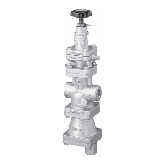
- Page 1 172-65260m-05 (S-COS/S-COSR Pressure Reducing Valve) 27 October 2008 ISO 9001/ ISO 14001 Manufacturer Kakogawa, Japan is approved by LRQA LTD. to ISO 9001/14001 Pressure Reducing Valve for Steam S-COS-16 / S-COSR-16 Copyright © 2008 by TLV CO., LTD. All rights reserved...
-
Page 2: Table Of Contents
Contents Introduction ................2 Safety Considerations ............3 Specifications ..............5 Acceptable Operating Range ..........5 Correct Usage of S-COS / S-COSR Pressure Reducing Valve6 Configuration..............8 Installation ................10 Adjustment ...............13 Maintenance..............14 Disassembly..............15 Reassembly ..............20 Troubleshooting ...............21 Product Warranty .............24 Introduction Thank you for purchasing the S-COS/S-COSR pressure reducing valve for steam. -
Page 3: Safety Considerations
• The three types of cautionary items above are very important for safety: be sure to observe all of them as they relate to installation, use, maintenance, and repair. Furthermore, TLV accepts no responsibility for any accidents or damage occurring as a result of failure to observe these precautions. - Page 4 CAUTION Be sure to use only the recommended components when repairing the product, and NEVER attempt to modify the product in any way. Failure to observe these precautions may result in damage to the product and burns or other injury due to malfunction or the discharge of fluids.
-
Page 5: Specifications
* Valve No. is displayed for products with options. This item is omitted from the nameplate when there are no options. Acceptable Operating Range Model S-COS-16 S-COSR-16 Primary Pressure Range 0.2 – 1.6 MPaG Within 10 – 84% of the primary pressure... -
Page 6: Correct Usage Of S-Cos / S-Cosr Pressure Reducing Valve6
Correct Usage of S-COS / S-COSR Pressure Reducing Valve Install properly and DO NOT use this product outside the recommended operating pressure, temperature and other specification ranges. CAUTION Improper use may result in such hazards as damage to the product or malfunctions which may lead to serious accidents. - Page 7 Precautions for the Installation of Additional Fittings Before or After the Reducing Valve In order to ensure stable steam flow, the piping upstream and downstream of the reducing valve must be straight runs. If a pressure reducing valve is installed either directly before or after an elbow or control valve, unevenness in steam flow may result in chattering and unstable pressure.
-
Page 8: Configuration
Configuration S-COS-16 No. Name Main Body Trap Body Trap Cover Separator Float Float Cover Trap Valve Seat Separator Screen Main Valve Seat 10 Main Valve 11 Piston 12 Cylinder 13 Pilot Screen 14 Pilot Screen Holder 15 Pilot Valve Body... - Page 9 S-COSR-16 No. Name Main Body Cover Plug Screen Main Valve Seat Main Valve Piston Cylinder Pilot Body Pilot Valve Stem 10 Pilot Valve Seat 11 Diaphragm 12 Pilot Screen 13 Pilot Screen Holder 14 Diaphragm Support 15 Coil Spring 16 Spring Housing 17 Adjustment Screw 18 Adjustment Handle 19 Plug...
-
Page 10: Installation
Installation Install properly and DO NOT use this product outside the recommended operating pressure, temperature and other specification ranges. CAUTION Improper use may result in such hazards as damage to the product or malfunctions which may lead to serious accidents. Local regulations may restrict the use of this product to below the conditions quoted. - Page 11 5. Maintenance Space S-COS S-COSR Leave sufficient space for maintenance, inspection and repair. (Unit: mm) 6. Trap Outlet Pipe (S-COS Only) For ease of maintenance, installation of a union connection is recommended for the trap outlet pipe. Connect the outlet pipe to a condensate Small Hole return line, or extend it to a trench.
- Page 12 Two-stage Pressure Reduction Two-stage pressure reduction should be performed whenever the pressure cannot be reduced to the desired level with a single pressure-reducing valve due to operating range limitations, such as when the reduction ratio is greater than 10:1. Bypass Valve Bypass Valve Safety Valve Pressure...
-
Page 13: Adjustment
Adjustment The S-COS/S-COSR pressure reducing valve should be properly adjusted for protection of the steam equipment against water hammer. 1. It is necessary to blow down all pipe lines thoroughly. The blowdown is especially important if the line is new or has been shut down for a long period of time. Take particular care to ensure that matter such as condensate and dirt does not remain inside the steam equipment. -
Page 14: Maintenance
Maintenance Take measures to prevent people from coming into direct contact with product outlets. Failure to do so may result in burns or other injury from CAUTION the discharge of fluids. Be sure to use only the recommended components when repairing the product, and NEVER attempt to modify the product in any way. -
Page 15: Disassembly
Disassembly NEVER apply direct heat to the float. The float may explode due to increased internal pressure, causing accidents leading to serious injury WARNING or damage to property and equipment. When disassembling or removing the product, wait until the internal pressure equals atmospheric pressure and the surface of the product CAUTION has cooled to room temperature. - Page 16 Disassembling the Pilot Section The diaphragm is removed by utilizing the notch in the pilot body. Loosen the pilot valve seat with a box wrench and remove it. Lift the pilot valve spring up and out with a pair of tweezers. Then loosen and remove the pilot screen holder to remove the pilot screen.
- Page 17 Disassembling the Separator and Main Valve (S-COS only) Turn the S-COS upside down for easy dismantling of the separator and main valve. Loosen the bolts and remove the trap body. Be careful, as the separator may drop off when the S-COS is returned to the normal attitude. Removal of the separator and pressed-in sleeve permits the removal of the main valve spring, the main valve and separator screen.
- Page 18 Disassembling the Main Valve (S-COSR Only) Turn the S-COSR upside down for easy dismantling of the main valve. Loosen and remove the cover plug. Removal of the cover plug and pressed-in sleeve permits the removal of the main valve, main valve spring and the screen. Loosen the main valve seat by using a box wrench and remove from the main body.
- Page 19 Exploded View S-COS S-COSR Adjustment Section Pilot Section Piston Section Separator / Main Valve Section Steam Trap Section 172-65260m-05 (S-COS/S-COSR Pressure Reducing Valve) 27 Oct 2008...
-
Page 20: Reassembly
Reassembly Assemble the unit using the same procedure as used for disassebling it; but in reverse order. Observe the following precautions: 1. The PTFE gaskets may be re-used if free from fault, crushing or deformation. 2. Apply anti-seize to the threaded portion of screws and bolts, the spring guide, ball and adjustment screw. -
Page 21: Troubleshooting
Troubleshooting NEVER apply direct heat to the float. The float may explode due to increased internal pressure, causing accidents leading to serious injury WARNING or damage to property and equipment. When disassembling or removing the product, wait until the internal pressure equals atmospheric pressure and the surface of the product CAUTION has cooled to room temperature. - Page 22 Troubleshooting Chart (continued) Problem Symptom Cause Remedy The secondary Adjustment is Flow rate exceeds Check the flow rate, pressure difficult, and set rated flow rate replace with a larger size cannot be pressure varies The adjustment screw Replace with a new adjusted or has seized adjustment screw...
- Page 23 Troubleshooting Chart (continued) Problem Symptom Cause Remedy Faulty steam Steam is blowing There is a build-up of Clean trap dirt on the trap valve (S-COS only) seat or at the float base The body is installed Check the piping tilted The float is deformed Check for water hammer Replace with a new float...
-
Page 24: Product Warranty
One year following product delivery. 2. Warranty Coverage TLV CO., LTD. warrants this product to the original purchaser to be free from defective materials and workmanship. Under this warranty, the product will be repaired or replaced at our option, without charge for parts or labor.
Need help?
Do you have a question about the S-COS-16 and is the answer not in the manual?
Questions and answers
how far from the PRV on either side can a pipe reducer be installed