mr. steam CU-4500 Installation, Operation & Maintenance Manual
Steambath generators
Hide thumbs
Also See for CU-4500:
- Installation, operation & maintenance manual (36 pages) ,
- Installation instructions manual (6 pages) ,
- Installation, operation & maintenance manual (34 pages)

Related Manuals for mr. steam CU-4500


Summary of Contents for mr. steam CU-4500
- Page 1 Installation, Operation & Maintenance Manual CU Series Steambath Generators Installation, Operation & Maintenance Manual Models: CU-360 through CU-4500 steam Feel Good Inc. ®...
-
Page 2: Table Of Contents
steam ® C U S E R I E S Installation, Operating & Maintenance Manual TABLE OF CONTENTS Before Installing ....... . .2 Steam Room Guidelines . -
Page 3: Before Installing
steam ® C U S E R I E S Installation, Operating & Maintenance Manual BEFORE INSTALLING IMPORTANT: T T a a k k e e t t i i m m e e t t o o r r e e a a d d t t h h e e s s e e i i n n s s t t r r u u c c t t i i o o n n s s t t h h o o r r o o u u g g h h l l y y b b e e f f o o r r e e i i n n s s t t a a l l l l i i n n g g o o r r s s e e r r v v i i c c i i n n g g . . A A l l t t h h o o u u g g h h t t h h i i s s C C U U S S t t e e a a m m b b a a t t h h G G e e n n e e r r a a t t o o r r h h a a s s b b e e e e n n q q u u a a l l i i f f i i e e d d f f o o r r s s h h i i p p m m e e n n t t b b y y M M r r . -
Page 4: Locating The Steambath Generator
Installation, Operating & Maintenance Manual LOCATING THE STEAM GENERATOR UNIT CAUTION (1-4): 1. Mr.Steam ® CU commercial steambath generators are 6. Install steambath generator on a solid and level surface, designed to NEMA Type 1 requirements and are intended for and mechanically secure generator in place. -
Page 5: Dimensional & Clearance Specifications
steam ® C U S E R I E S Installation, Operating & Maintenance Manual DIMENSIONS & CLEARANCE SPECIFICATIONS Pressure High Limit Operating Steam Outlet Gauge Pressure Pressure 15 PSIG Control Control Safety Valve On/Off Switch Gauge Glass Assembly Height MM 150 Liquid Level Control (see note 2) -
Page 6: Selecting The Steambath Generator
_____________________________________________________________________________________________________ CU-3000 3000 1/2" 1" _____________________________________________________________________________________________________ CU-4500 4500 1/2" 1-1/2" _____________________________________________________________________________________________________ *After taking into consideration all factors affecting resultant steam room volume, including materials of construction, distance from genera- tor to steam room, interior height of steam room ceiling, outside/exterior walls and windows etc, select proper Model CU generator. Consult... -
Page 7: Installation: Plumbing, Water Supply, Steam Line, Drain, Safety Valve
steam ® C U S E R I E S Installation, Operating & Maintenance Manual INSTALLATION Steam Line P P l l u u m m b b i i n n g g All plumbing shall be performed by a qualified 1. -
Page 8: Steam Room Guidelines
12 inches above steam room floor and install Mr.Steam PN CU-103985 acrylic shield on each steamhead. Steam Steam Head IMPORTANT: For Steam rooms using acrylic, fiberglass or... -
Page 9: Electric
CU-2500 ____________________________________________________________________________________________________________________________ CU-3000 ____________________________________________________________________________________________________________________________ CU-4500 ____________________________________________________________________________________________________________________________ IMPORTANT: Use minimum 90° C insulated copper conductors only for field wiring sized in accordance with National and local electric Codes. NOTE: Consult factory for other voltage/phase combinations. CU generators are suitable for 50/60 hz. -
Page 10: Wiring
steam ® C U S E R I E S Installation, Operating & Maintenance Manual WIRING CAUTION 3. IMPORTANT: Insure all electrical connections are sufficient- To avoid possible electric shock, the steambath generator shall be suitably grounded in ly tightened prior to energizing generator. See pg. 8, Item 5. accordance with National Electric and local Codes. -
Page 11: Control Circuit Wiring Diagrams
steam ® C U S E R I E S Installation, Operating & Maintenance Manual CONTROL CIRCUIT WIRING DIAGRAM SEE PAGES 11, 12 & 13 FOR DIAGRAMS CAUTION Installer shall use a safety switch of adequate capacity employing suitably rated circuit breakers or fuses between main electrical power source(s) and the generator. - Page 12 steam ® C U S E R I E S Installation, Operating & Maintenance Manual CONTROL CIRCUIT WIRING DIAGRAM Digital 1 Temperature Control System and optional automatic blowdown assembly ® For Models: CU-360A to CU-750A and CU-1000AF3, CU-1250AF3, CU-1400AF3 NOTES: 1.
- Page 13 steam ® C U S E R I E S Installation, Operating & Maintenance Manual CONTROL CIRCUIT WIRING DIAGRAM Digital 1 Temperature Control System and optional automatic blowdown assembly For Models: CU-1000AB3, CU-1000AC3, CU-1250AB3, CU-1250AC3, CU-1400AB3, CU-1400AC3 NOTES: 1. Larger rooms may require two or more steam solenoid valves in parallel. 2.When generator services two rooms, second room requires a Digital 1 and Solenoid Valve(s).
- Page 14 steam ® C U S E R I E S Installation, Operating & Maintenance Manual CONTROL CIRCUIT WIRING DIAGRAM ® Models CU-2000 and higher with Digital 1 Temperature Control System and Optional Automatic Blowdown Assembly GROUND TERMINAL BLOCK IMPORTANT: 1. Digital 1 ®...
-
Page 15: Digital 1 Control: Contents
steam ® C U S E R I E S Installation, Operating & Maintenance Manual DIGITAL 1 KIT CONTENTS ® Digital 1 Sensor Digital 1 Control and 30 ft. Cable Acrylic Shield Mr. Steam CU Steambath Generator can be used for one or two steam rooms in accordance with Page 5, Item D. -
Page 16: Control Installation
steam ® C U S E R I E S Installation, Operating & Maintenance Manual DIGITAL 1 ® CONTROL INSTALLATION NOTE: If the steam generator came with a factory installed Digital 1 control skip to page 16. ® Hazard of Electric Shock. WARNING Disconnect all power supplies before making wiring connections. -
Page 17: Temperature Sensor Installation
steam ® C U S E R I E S Installation, Operating & Maintenance Manual DIGITAL 1 ® OPERATING TEMPERATURE SENSOR INSTALLATION • Locate sensor on a wall inside the steam room five (5) feet above the floor. DO NOT LOCATE THE DIGITAL 1 SENSORS NEAR OR ABOVE THE STEAMHEAD(S) AS THIS MAY CAUSE DIRECT STEAM EMISSION TO INTERFERE WITH STEAMROOM TEMPERATURE REGULATION. -
Page 18: Installation
steam ® C U S E R I E S Installation, Operating & Maintenance Manual AUTOMATIC BLOWDOWN SYSTEM KIT INSTALLATION NOTE: If the steam generator came with a factory installed Automatic Blowdown System see page 22 on how to program Terminal Block the timer. -
Page 19: Auxiliary Manual Reset Low Water Cutoff
C U S E R I E S Installation, Operating & Maintenance Manual PRINCIPLES OF OPERATION MR.STEAM CU Steambath Generators require two sources The Digital 1 Kit is provided with Over Temperature of electrical supply – power voltage and control voltage. - Page 20 steam ® C U S E R I E S Installation, Operating & Maintenance Manual AUTOMATIC BLOWDOWN OPERATION & TESTING NOTE: The Time Clock controls boiler operation. The boiler is on when the timer is on. The Blowdown Valve will open when the timer turns the boiler off.
-
Page 21: Operating And Testing Automatic Blowdown, Digital 1 Control, Cu-Hl
steam ® C U S E R I E S Installation, Operating & Maintenance Manual OPERATION INDICATORS OUT 1: The LED under OUT 1 is on during normal operating con- ditions. If the light under OUT 1 is off the Digital 1 is in backup temperature mode, an alarm will sound, the display will flash and the steam bath generator will be off. -
Page 22: Warning Signage
Use care when entering or exiting the steam room. Floors may be slippery and dangerous due to moisture. Use of proper footwear is recommended at all times. Note: For additional safety considerations see Owners manual. mr.steam ® 43-20 34th Street, Long Island City, NY 11101 1-800-76-STEAM www.mrsteam.com... -
Page 23: Operation
steam ® C U S E R I E S Installation, Operating & Maintenance Manual OPERATION CAUTION With all power disconnected at main the desired steam room setting at the sensor switch, insure all electrical and mechanical connec- (range 100°F – 120°F). Operating temperature is at the dis- tions are tight before energizing unit to prevent cretion of the owner/operator. -
Page 24: Maintenance Instructions
steam ® C U S E R I E S Installation, Operating & Maintenance Manual MAINTENANCE INSTRUCTIONS To establish a good preventive maintenance pro- 4. Generators equipped with level probes (Models CU 2000 - gram, we suggest that the site equipment fore- CU 1400) for maintaining operating water level and probe man, engineer or owner/operator familiarize them- for auxiliary low water cut-off protection need special con-... -
Page 25: Water Gauge & Gauge Glass Installation
steam ® C U S E R I E S Installation, Operating & Maintenance Manual WATER GAUGE & GAUGE GLASS INSTALLATION Only properly trained personnel should IMPORTANT: Top Gauge install and maintain water gauge glass and connections. Fitting Pressure in generator must be at zero before proceeding. Remember to wear safety gloves and glasses during instal- lation. -
Page 26: Water Gauge & Gauge Glass Use And Care
steam ® C U S E R I E S Installation, Operating & Maintenance Manual WATER GAUGE & GAUGE GLASS 24-HOUR AND 7-DAY TIME SWITCHES USE AND CARE NOTE: The Time Clock controls boiler operation. The boiler is on when the timer is on. The Blowdown Valve D D O O N N O O T T s s will open when the Timer turns the Boiler off. -
Page 27: Trouble Shooting
steam ® C U S E R I E S Installation, Operating & Maintenance Manual TROUBLE SHOOTING To prevent risk of electric shock, trouble shooting should be done only by a qualified licensed electrician CAUTION __________________________________________________________________________________________________________________ Problem Probable Cause Suggested Remedy __________________________________________________________________________________________________________________ No water in generator Water supply is "OFF"... -
Page 28: Check
steam ® C U S E R I E S Installation, Operating & Maintenance Manual CHECK Steam Solenoid Valve PC Board - Models CU 360, CU 500, CU 750, CU 1000, CU 1400 1. Check voltage rating of solenoid valve (120 VAC for United States, Canada, Mexico;... -
Page 29: Element Replacement Instructions
steam ® C U S E R I E S Installation, Operating & Maintenance Manual INSTRUCTIONS FOR ELEMENT REPLACEMENT R R E E A A D D I I N N S S T T R R U U C C T T I I O O N N S S C C O O M M P P L L E E T T E E L L Y Y B B E E F F O O R R E E S S T T A A R R T T I I N N G G W W O O R R K K CAUTION Before Installing your new elements be sure McDonnell Miller low water cut-off and aux. -
Page 30: Typical Component Arrangement Cu 360-Cu 1400
steam ® C U S E R I E S Installation, Operating & Maintenance Manual Hi-Limit Operating CU 360-CU 1400 Pressure Pressure Control Control TYPICAL COMPONENT Steam Outlet Terminal ARRANGEMENT Block Data Plate Pressure Gauge Contactors Gauge Glass On/Off Switch 24hr/7day Blowdown Clock Heating Elements... -
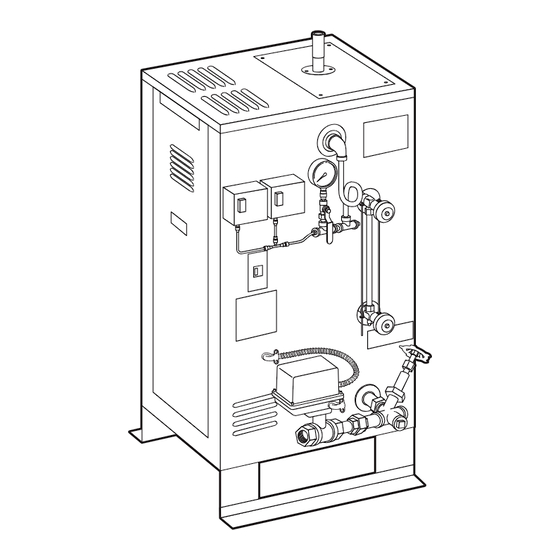
Page 31: Cu 2000-Cu4500
steam ® C U S E R I E S Installation, Operating & Maintenance Manual COMMERCIAL STEAMBATH REPLACEMENT PARTS Models CU 360 – CU 4500 ________________________________________________________________________ ______________________________________________________________ PART # DESCRIPTION PART # DESCRIPTION ________________________________________________________________________ ______________________________________________________________ ELECTRIC (cont.) BLOWDOWN ________________________________________________________________________ ______________________________________________________________ 99314 Power Fuses 208/240V 60A 250V 99353... -
Page 32: Replacement Parts List
steam ® C U S E R I E S Installation, Operating & Maintenance Manual COMMERCIAL STEAMBATH REPLACEMENT PARTS Models CU 360 – CU 4500 ______________________________________________________ _______________________________________________________ PART # DESCRIPTION PART # DESCRIPTION ______________________________________________________ _______________________________________________________ PRESSURE CONTROL WATER FEED & STEAM SOLENOIDS _______________________________________________________ ______________________________________________________ 99113R...
Need help?
Do you have a question about the CU-4500 and is the answer not in the manual?
Questions and answers