mr. steam CU-360 Installation, Operation & Maintenance Manual
Cu series
Hide thumbs
Also See for CU-360:
- Installation, operation & maintenance manual (34 pages) ,
- Installation instructions manual (6 pages) ,
- Installation, operation & maintenance manual (32 pages)

Related Manuals for mr. steam CU-360


Summary of Contents for mr. steam CU-360
- Page 1 Installation, Operation & Maintenance Manual CU Series Steambath Generators Installation, Operation & Maintenance Manual Models: CU-360 through CU-4500 steam Feel Good Inc. ®...
-
Page 2: Table Of Contents
steam ® C U S E R I E S Installation, Operating & Maintenance Manual TABLE OF CONTENTS Before Installing ....... . .3 Steam Room Guidelines . -
Page 3: Before Installing
3. Verify the correct steam generator sizing by referring to sories or products on the generator or generator piping. the Mr. Steam sizing guide. See page 6. 4. DO NOT use black iron pipe or galvanized pipe for the IMPORTANT: The Mr. Steam Digital 1 System operating steam line. -
Page 4: Locating The Steam Generator Unit
Specifications” information on pg. 5-6. See page 6 for guid- RECOMMENDED. ance if generator is more than 25 feet from steam room. 6. Install steambath generator on a solid and level surface, and mechanically secure generator in place. MR. STEAM INSTALLATION Figure 1: FOR ILLUSTRATIVE PURPOSES ONLY Steam Generator 1"... -
Page 5: Selecting The Steam Generator
Example: A steam room 8' x 9' x 8' = 576 cu. ft. (volume). the combined resultant room volume of the two rooms should Select the Mr. Steam Model which is the next larger volume. not exceed 1000 cubic feet. - Page 6 Typical Arrangement of Boiler with McDonnell Miller. For illustration purposes only. Refer to all notes below 1. All dimensions are approximate. 2. MM150 Liquid Level Control on CU-2000 and larger models only. CU-360 to CU-1400 have electronic liquid level 37.2 controls. 13.5 12.6 15.7 16.4...
- Page 7 steam ® C U S E R I E S Installation, Operating & Maintenance Manual 17.2 DIMENSIONS (cont.) Front Right Side Figure 4: CU4500 51.5 25.8 16.0 10.3 18.1 18.7 28.3 30.6 31.3 34.2...
- Page 8 For illustration purposes only. Refer to all notes below Service Area Clearance MIN* 1. MM150 Liquid Level Control on CU-2000 and larger models only. CU-360 to CU- Panel 1400 have electronic liquid level controls. Clearance 2. IMPORTANT: Minimum Clearance from Combustible Surfaces: 1"...
- Page 9 steam ® C U S E R I E S Installation, Operating & Maintenance Manual CLEARANCE SPECIFICATIONS (cont.) Figure 7: CU4500 Service Area Clearance MIN* 36 MIN* MIN** Service Area Clearance 1 MIN* 36 MIN* Panel 16 MIN* Service Area Clearance Clearance *Access to service areas to be supplied by customer.
-
Page 10: Installation: Plumbing, Water Supply, Steam Line, Drain, Safety Valve
steam ® C U S E R I E S Installation, Operating & Maintenance Manual INSTALLATION Steam Line P P l l u u m m b b i i n n g g All plumbing shall be performed by a qualified 1. -
Page 11: Steam Room Guidelines
103985) over the steamhead until the tabs engage the grooves in the steamhead. Acrylic Sheild IMPORTANT: Do not use with fragrance containing Fully Assembled aldehydes. Acrylic Shield damage may result. Mr. Steam oils are approved for use with this acrylic shield. Diagram B... -
Page 12: Electric & Wiring
3 PH 1 PH 3 PH 3 PH 3 PH inside the steam room. Locate approximately 5 CU-360 feet above the steam room floor, preferably CU-500 away from steam heads. CU-750 5. The steam solenoid valve(s) shall be located CU-1000... -
Page 13: Wiring Diagrams
steam ® C U S E R I E S Installation, Operating & Maintenance Manual TYPICAL POWER WIRING DIAGRAM 3PH Power Supply __ __ __ __ Field Wiring __________ Factory Wiring Power Terminal Block 3PH Power Supply Power Contactor Power Contactors Heating Element Heating Elements Diagram #1... - Page 14 steam ® C U S E R I E S Installation, Operating & Maintenance Manual CONTROL CIRCUIT WIRING DIAGRAM Digital 1 Temperature Control System and optional automatic blowdown assembly ® For Models: CU-360A to CU-750A and CU-1000AF3, CU-1250AF3, CU-1400AF3 HIGH PROBE (WF/LWCO) NOTES: 1.
- Page 15 steam ® C U S E R I E S Installation, Operating & Maintenance Manual CONTROL CIRCUIT WIRING DIAGRAM Digital 1 Temperature Control System and optional automatic blowdown assembly For Models: CU-1000AB3, CU-1000AC3, CU-1250AB3, CU-1250AC3, CU-1400AB3, CU-1400AC3 NOTES: 1. Larger rooms may require two or more steam solenoid valves in parallel. 2.
-
Page 16: Wiring Diagrams
steam ® C U S E R I E S Installation, Operating & Maintenance Manual CONTROL CIRCUIT WIRING DIAGRAM ® Models CU-2000 and higher with Digital 1 Temperature Control System and Optional Automatic Blowdown Assembly REMOVE JUMPER FOR 2nd OVER TEMP. SHUT OFF HIGH PROBE... -
Page 17: Digital 1 Control
Digital 1 Control and 30 ft. Cable Acrylic Shield Mr. Steam CU Steambath Generator can be used for one or two steam rooms in accordance with guidelines for generator selection on page 6. Each room requires one Digital 1 Kit sized for the room. -
Page 18: Control Installation
steam ® C U S E R I E S Installation, Operating & Maintenance Manual DIGITAL 1 ® CONTROL INSTALLATION Control Panel Showing Control Panel Showing One Digital 1 Control Two Digital 1 Controls ® ® NOTE: If the steam generator came with a factory installed Digital 1 control, skip to Sensor Installation. -
Page 19: Principles Of Operation
A lighted decreases, the liquid level control will energize the water ON/OFF switch activates the control circuit. MR. STEAM CU solenoid valve on and off and maintain proper water level. Generators are equipped with automatic liquid level/low water IMPORTANT: Owners/operators should obtain a copy and cut-off control. -
Page 20: Automatic Blowdown System
steam ® C U S E R I E S Installation, Operating & Maintenance Manual AUTOMATIC BLOWDOWN SYSTEM CU 81600 The Automatic Blowdown System consists of the following factory installed items: • Blowdown Control Panel • Motorized Drain Valve Assembly #CU-81600 AUTOMATIC BLOWDOWN SYSTEM KIT INSTALLATION NOTE: If the steam generator came with a factory installed Automatic Terminal Block... -
Page 21: Operating And Testing Auto Blowdown, Digital 1 Control, Cu-Hl
5. Turn the override switch to automatic ( ). NOTE: ASME blowdown separator tank systems are available SETTING OPERATING TEMPERATURE from Mr. Steam. For more information please contact Mr. Steam 1. Press the SET button twice, the light under OUT 2 at 1-800-76 STEAM. -
Page 22: 30-Minute Timer
steam ® C U S E R I E S Installation, Operating & Maintenance Manual OPERATION INDICATORS MESSAGE DISPLAY Under normal operation, the actual room temperature will be OUT 1: The LED under OUT 1 is on during normal operating displayed, the following messages may also appear (the Digital1 conditions. -
Page 23: Warning Signage
steam ® C U S E R I E S Installation, Operating & Maintenance Manual WARNING SIGNAGE The CU Steambath generator is provided with a WARNING sign. This WARNING is to be secured 1. Exit immediately if uncomfortable, dizzy or sleepy. Staying too long in a heated to the outside of the steam room, on the steam- area is capable of causing overheating. -
Page 24: Operation
Consult with a licensed plumber. d. Close wall-mounted safety switch NOTE: ASME blowdown separator tank systems are avail- able from Mr. Steam. For more information please contact Mr. Steam at 1-800-76 STEAM. AUTOMATIC BLOWDOWN INSTRUCTIONS Automatic Blowdown Systems drain the steambath... -
Page 25: Maintenance Instructions
steam ® C U S E R I E S Installation, Operating & Maintenance Manual MAINTENANCE INSTRUCTIONS To establish a good preventive maintenance pro- 4. Generators equipped with level probes (Models CU360 - gram, we suggest that the site equipment fore- 1400) for maintaining operating water level and probe for man, engineer or owner/operator familiarize auxiliary low water cut-off protection need special consider-... -
Page 26: Water Gauge & Gauge Glass Installation
steam ® C U S E R I E S Installation, Operating & Maintenance Manual WATER GAUGE & GAUGE GLASS INSTALLATION Only properly trained personnel should install IMPORTANT: Top Gauge and maintain water gauge glass and connections. Pressure in Fitting generator must be at zero before proceeding. -
Page 27: Water Gauge & Gauge Glass Use And Care
steam ® C U S E R I E S Installation, Operating & Maintenance Manual WATER GAUGE & GAUGE GLASS 24-HOUR AND 7-DAY TIME SWITCHES USE AND CARE NOTE: The Time Clock controls boiler operation. The boiler is ON when the timer is ON. The Blowdown Valve will open when D D O O N N O O T T s s the Timer turns OFF. -
Page 28: Trouble Shooting
steam ® C U S E R I E S Installation, Operating & Maintenance Manual TROUBLE SHOOTING To prevent risk of electric shock, trouble shooting should be done only by a qualified licensed electrician CAUTION __________________________________________________________________________________________________________________ Problem Probable Cause Suggested Remedy __________________________________________________________________________________________________________________ No water in generator Water supply is "OFF"... -
Page 29: Troubleshooting Guide
steam ® C U S E R I E S Installation, Operating & Maintenance Manual TROUBLESHOOTING GUIDE IMPORTANT: Read all warnings and instructions TROUBLESHOOTING THE 103538C BOARD before performing any installation, maintenance, or Perform the steps below to verify proper function troubleshooting. - Page 30 steam ® C U S E R I E S Installation, Operating & Maintenance Manual TROUBLESHOOTING GUIDE (cont.) CAUTION STEP 6 & 7: Check these terminal points Be sure to slowly release pressure to zero (0) against a ground or to the boiler jacket and veri- psig before resuming operation of steam bath generator.
-
Page 31: Pc Boards, Probes, Steam Solenoid Valve, Digital 1 Control, Heating Element
Voltage should be as marked on nameplate. Models CU-360 through CU-1400 are equipped with two probes for low water cut-off (LWCO) and water feed control. Failure to 2. Using an ammeter, measure total current draw as per name- clean the probes may result in generator not operating, overflow plate rating. -
Page 32: Element Replacement Instructions
steam ® C U S E R I E S Installation, Operating & Maintenance Manual INSTRUCTIONS FOR ELEMENT REPLACEMENT R R E E A A D D I I N N S S T T R R U U C C T T I I O O N N S S C C O O M M P P L L E E T T E E L L Y Y B B E E F F O O R R E E S S T T A A R R T T I I N N G G W W O O R R K K CAUTION Before Installing your new elements be sure McDonnell Miller low water cut-off and aux. -
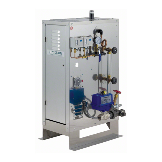
Page 33: Typical Component Arrangement Cu 360-Cu 1400
steam ® C U S E R I E S Installation, Operating & Maintenance Manual LABEL FUNCTION CU 360-1400 Typical Component A Steam Outlet Front Right Side Arrangement B Water Inlet C Drain Outlet Terminal D Optional Automatic Blocks Liquid Blowdown Valve Level Control... -
Page 34: Replacement Parts List
steam ® C U S E R I E S Installation, Operating & Maintenance Manual COMMERCIAL STEAMBATH REPLACEMENT PARTS Models CU 360 – CU 4500 ________________________________________________________________________ ______________________________________________________________ PART # DESCRIPTION PART # DESCRIPTION ________________________________________________________________________ ______________________________________________________________ ELECTRIC (cont.) BLOWDOWN _______________________________________________________________ ______________________________________________________________ 99316 Power Fuses 480V 60A 600V 99353... -
Page 35: Warranty
⁄ " Polished Chrome ______________________________________________________ 103985 Acrylic Shield ______________________________________________________ CU-99216B 30 Minute Mechanical Timer ______________________________________________________ CU-99216DIG 30 Minute Digital Countdown Timer ______________________________________________________ WARRANTY To view or download the Mr. Steam Residential Generator Warranty blog.mrsteam.com/wr and register your Product go to:... -
Page 36: Sussman-Automatic Corporation
steam ® Feel Good Inc. ™ www.mrsteam.com Products, information and specifications are subject to change without notice. For more information call Sales & Support at 1.800.76.STEAM (East Coast) or 1.800.72.STEAM (West Coast) for more information. ––––––––––––––––––––––––––––––––––––––––––––––––––––––––––––––––––––––––––––––––––––––––––––––––––––– mr.steam ® Sussman-Automatic Corporation ®...
Need help?
Do you have a question about the CU-360 and is the answer not in the manual?
Questions and answers