mr. steam CU-360 Installation, Operation & Maintenance Manual
Cu series steambath generators
Hide thumbs
Also See for CU-360:
- Installation, operation & maintenance manual (36 pages) ,
- Installation instructions manual (6 pages) ,
- Installation, operation & maintenance manual (32 pages)
Table of Contents
Advertisement
CU Series Steambath Generators
Installation, Operation & Maintenance Manual
Models: CU-360 through CU-4500
___________________________________________________________
IMPORTANT: LEAVE THIS MANUAL WITH THE OWNER/OPERATOR
___________________________________________________________
Table of Contents
Before Installing . . . . . . . . . . . . . . . . . . . . . . . . . . . . .2
Steam Room Guidelines . . . . . . . . . . . . . . . . . . . . . . . .2
Locating the Steambath Generator . . . . . . . . . . . . . . . .3
Dimensional & Clearance Specifications . . . . . . . . . . . . .4
Selecting the Steambath Generator . . . . . . . . . . . . . . . .5
Plumbing, Water Supply, Steam Line, Drain, Safety Valve
Water Quality Information . . . . . . . . . . . . . . . . . . . . . .6
Electric . . . . . . . . . . . . . . . . . . . . . . . . . . . . . . . . . . .8
Wiring . . . . . . . . . . . . . . . . . . . . . . . . . . . . . . . . . . . .9
Control Circuit Wiring Diagrams . . . . . . . . . . . . . . .10-13
Kit Contents . . . . . . . . . . . . . . . . . . . . . . . . . . . . . . . . . . . . . .
Control Installation . . . . . . . . . . . . . . . . . . . . . . . . . . . . . . . . .
Operating Temperature Sensor Installation . . . . . . . . . . . . . . . . .
CU-HL Installation . . . . . . . . . . . . . . . . . . . . . . . . . . .17
Kit Contents . . . . . . . . . . . . . . . . . . . . . . . . . . . . .17
Installation . . . . . . . . . . . . . . . . . . . . . . . . . . . . . .18
Auxiliary Manual Reset Low Water Cutoff . . . . . . . . . . .19
Principles of Operation . . . . . . . . . . . . . . . . . . . . . . .20
Automatic Blowdown, F1 Plus Control, CU-HL . . . . . .21
Warning Signage . . . . . . . . . . . . . . . . . . . . . . . . . . . .22
Pre-Operation Check . . . . . . . . . . . . . . . . . . . . . . . . .22
Automatic Blowdown Instructions . . . . . . . . . . . . . .23
Manual Blowdown Instructions . . . . . . . . . . . . . . . .23
Maintenance Instructions . . . . . . . . . . . . . . . . . . . . . .24
24-hour and 7-day Time Switches . . . . . . . . . . . . . . . .25
Water Gauge & Gauge Glass Installation . . . . . . . . . . .26
Use and Care . . . . . . . . . . . . . . . . . . . . . . . . . . . . .27
Trouble Shooting . . . . . . . . . . . . . . . . . . . . . . . . . . .28
F1 Plus Control, Heating Element . . . . . . . . . . . . . .29
Element Replacement Instructions . . . . . . . . . . . . . . .30
mr
.
steam
43-20 34th Street
®
®
Long Island City, NY 11101
Sussman-Automatic Corp
Tel: 1-800-76 STEAM
info@mrsteam.com
Fax: (718) 472-3256
www.mrsteam.com
. .6
14
15
16
. . . . . . . .16
Typical CU Series Steambath Generator
IMPORTANT NOTE:
As you follow these instructions, you will notice warning and
caution symbols. This information is important for the safe and
efficient installation and operation of this steam generator.
There are two types of potential hazards that may occur during
this installation and operation:
!
C A U T I O N
uct damage may occur if you do not follow instructions.
!
WA R N I N G
or death if precautions are not followed.
9410 S. La Cienega Blvd.
Inglewood CA 90301
1-800 -72 STEAM
Fax: (310) 216-2944
(for illustrative purposes only)
signals a situation where injury or prod-
states a hazard may cause serious injury
PUR 100376 3/07
Advertisement
Table of Contents

Related Manuals for mr. steam CU-360


Summary of Contents for mr. steam CU-360
-
Page 1: Table Of Contents
CU Series Steambath Generators Installation, Operation & Maintenance Manual Models: CU-360 through CU-4500 ___________________________________________________________ IMPORTANT: LEAVE THIS MANUAL WITH THE OWNER/OPERATOR ___________________________________________________________ Table of Contents Before Installing ......2 Steam Room Guidelines . -
Page 2: Before Installing
steam ® CU Series Installation, Operating & Maintenance Manual _________________________________________________________________ Before Installing or Servicing IMPORTANT: Take time to read these instructions thoroughly before installing or servicing. Although this CU Steambath Generator has been qualified for shipment by mr.steam, the following must be reviewed for proper and safe use. 1. -
Page 3: Locating The Steambath Generator
steam ® CU Series Installation, Operating & Maintenance Manual _________________________________________________________________ Locating the Steam Generator Unit ® mr.steam CU commercial steambath generators are designed to NEMA Type 1 requirements and C A U T I O N are intended for indoor use only. They are to be located indoors in a dry, clean location and are not to be subjected to moisture, condensate, hose wash down or the like. -
Page 4: Dimensional & Clearance Specifications
1. IMPORTANT: Allow minimum of 36" all around for servicing 2. All dimensions are approximate. Refer to chart on Page 5. 3. MM150 Liquid Level Control on CU-2000 and larger models only. CU-360 to CU-1400 have electronic liquid level controls. -
Page 5: Selecting The Steambath Generator
Maximum* Water Inle Steam Generator Dimensions (inches) Shipping Model No. Room Volume (cu ft) Size NPT Outlet Size, NPT Width Length Height Wt.Lbs. CU-360 1/4" 1" ___________________________________________________________________________________________________ CU-500 1/4" 1" ___________________________________________________________________________________________________ CU-750 1/4" 1" ___________________________________________________________________________________________________ CU-1000 1000 1/4"... -
Page 6: Installation
steam ® CU Series Installation, Operating & Maintenance Manual _________________________________________________________________ Installation Plumbing All plumbing shall be performed by a qualified licensed plumber and in accordance with applicable National and local Codes. Water Supply 1. Connect to hot or cold water line. A hot water line is preferable, however incoming hot water should not exceed 160° F. The low temperature setting on many hot water heaters provides 120°F water IMPORTANT: 2. -
Page 7: Steam Room Guidelines - Steam Head, Acrylic Shield
steam ® CU Series Installation, Operating & Maintenance Manual _________________________________________________________________ Steam Room Guidelines IMPORTANT: The following general information should be used in conjunction with your architect, designer and contractor in determining all factors necessary in providing a suitable and safe steam room environment for your bathers. IMPORTANT: Owners/operators should obtain a copy and familiarize themselves with the latest edition of the American College Sports Medicine Health/Fitness Faculty Standards and Guidelines, or a similar resource and reference publication, and refer to those guidelines for the proper and safe operation of a spa facility including steam rooms. -
Page 8: Electric
AMPERAGE CHART - Indicates Total Ampere Draw of Specific CU Model at Voltage & Phase Specified ________________________________________________________________________________________________ Model No. 208V/1 PH 208V/3 PH 240V/1 PH 240V/3 PH 480V/3 PH 600V/3 PH ________________________________________________________________________________________________ CU-360 ________________________________________________________________________________________________ CU-500 ________________________________________________________________________________________________ CU-750 ________________________________________________________________________________________________ CU-1000 ________________________________________________________________________________________________ CU-1250 ________________________________________________________________________________________________... -
Page 9: Wiring
steam ® CU Series Installation, Operating & Maintenance Manual _________________________________________________________________ Wiring C A U T I O N To avoid possible electric shock, the steambath generator shall be suitably grounded in accordance with National Electric and local Codes. Disconnect all power supplies at the main disconnect switch before proceeding. - Page 10 steam ® CU Series Installation, Operating & Maintenance Manual _________________________________________________________________ Control Circuit Wiring Diagram SEE PAGES. 11, 12 & 13 FOR DIAGRAMS NOTES: 1. Larger rooms may require two or more steam solenoid valves in parallel. 2. When generator services two rooms, second room requires a set of F1 Plus solenoid valves and CU-HL.
-
Page 11: Control Circuit Wiring Diagrams
steam ® CU Series Installation, Operating & Maintenance Manual _________________________________________________________________ Control Circuit Wiring Diagram F1 Plus Temperature Control System and optional automatic blowdown assembly For Models: CU-360A to CU-750A and CU-1000AF3, CU-1250AF3, CU-1400AF3 120 VAC INPUT 2nd CU-HL HIGH PROBE 6"... - Page 12 steam ® CU Series Installation, Operating & Maintenance Manual _________________________________________________________________ Control Circuit Wiring Diagram F1 Plus Temperature Control System and optional automatic blowdown assembly For Models: CU-1000AB3, CU-1000AC3, CU-1250AB3, CU-1250AC3, CU-1400AB3, CU-1400AC3 120 VAC INPUT 2nd CU-HL HIGH PROBE 6" L E G E N D Factory Wiring CU-HL...
- Page 13 steam ® CU Series Installation, Operating & Maintenance Manual Control Circuit Wiring Diagram Models CU-2000 and higher with F1 Plus Temperature Control System and Optional Automatic Blowdown Assembly Control Supply 120 Volts 1PH 60Hz L E G E N D Factory Wiring Field Wiring Ground...
-
Page 14: F1 Plus Kit Contents
steam ® CU Series Installation, Operating & Maintenance Manual _________________________________________________________________ ® F1 Plus Kit Contents F1 Plus Control (Front) F1 Plus Sensor CU-HL Hi Limit Control Acrylic Shield Mr.Steam CU Steambath Generator can be used for one or two steam rooms in accordance with Page 5, Item D. Each room requires one F1 Plus Kit sized for the room. -
Page 15: Control Installation
steam ® CU Series Installation, Operating & Maintenance Manual _________________________________________________________________ ® F1 Plus Control Installation WA R N I N G Hazard of Electric Shock. Disconnect all power supplies before making wiring connections. NOTE: Reference applicable wiring diagram. 1. Remove 4" diameter blank cover located on steam generator. Mount the F1 Plus faceplate on the back of the generator cabinet with provided screws and nuts. -
Page 16: Operating Temperature Sensor Installation
steam ® CU Series Installation, Operating & Maintenance Manual ® F1Plus Operating Temperature Sensor Installation • Locate sensor on a wall inside the steam room five (5) feet above the floor. DO NOT LOCATE THE F1 PLUS SENSORS NEAR OR ABOVE THE STEAMHEAD(S) AS THIS MAY CAUSE DIRECT STEAM EMISSION TO INTERFERE WITH STEAMROOM TEMPERATURE REGULATION. -
Page 17: Cu-Hl Installation
steam ® CU Series Installation, Operating & Maintenance Manual _________________________________________________________________ CU-HL Installation NOTE: Reference applicable wiring diagram, pgs. 11, 12 & 13. 1. Model CU-HL room temperature control unit must be installed 6. Secure sensing bulb to the wall with the sensor bulb guard provided outside the steam room. -
Page 18: Installation
steam ® CU Series Installation, Operating & Maintenance Manual _________________________________________________________________ Automatic Blowdown System Kit Installation WA R N I N G Hazard of Electric Shock. Disconnect all power supplies before making wiring connections. Note: Reference applicable wiring diagram. Terminal Block 1. -
Page 19: Auxiliary Manual Reset Low Water Cutoff
steam ® CU Series Installation, Operating & Maintenance Manual _________________________________________________________________ Auxiliary Manual Reset Low Water Cutoff WA R N I N G Hazard of Electric Shock. Disconnect all power supplies before making wiring connections. Make sure boiler is not hot and has no pressure and is drained. NOTE: Reference applicable wiring diagram. -
Page 20: Principles Of Operation
steam ® CU Series Installation, Operating & Maintenance Manual _________________________________________________________________ Principles of Operation MR.STEAM CU Steambath Generators require two sources of electrical supply – power voltage and control voltage. Power voltage is usually 208, 240, or 480 volt, single or three phase. Control voltage for generator suitable for operation with these voltages is 120V, 1PH. -
Page 21: Operating And Testing Automatic Blowdown, F1 Plus Control, Cu-Hl
steam ® CU Series Installation, Operating & Maintenance Manual _________________________________________________________________ Automatic Blowdown Operation and Testing WA R N I N G Burn Hazard. Pressurized Steam and Hot Water is discharged during blowdown. 1. Turn the override switch to permanent ON (I). 2. -
Page 22: Warning Signage
steam ® CU Series Installation, Operating & Maintenance Manual _________________________________________________________________ Warning Signage The CU Steambath generator is provided with a WARNING sign. This WARNING is to be secured to the outside of the steam room, on the steam 1. Exit immediately if uncomfortable, dizzy or sleepy. Staying too long in a heated room door or adjacent to that door. -
Page 23: Operation
steam ® CU Series Installation, Operating & Maintenance Manual _________________________________________________________________ Operation C A U T I O N With all power disconnected at main switch, insure all electrical and mechanical connections are tight before energizing unit to prevent electrical problems and mechanical leaks. 1. -
Page 24: Maintenance Instructions
steam ® CU Series Installation, Operating & Maintenance Manual _________________________________________________________________ Maintenance Instructions To establish a good preventive maintenance program, we suggest that the site equipment foreman, engineer or owner/operator familiarize themselves with these guidelines: at max 5 PSIG operating pressure is recommended for best steambath generator 1. -
Page 25: 24-Hour And 7-Day Time Switches
steam ® CU Series Installation, Operating & Maintenance Manual _________________________________________________________________ 24-Hour and 7-day Time Switches PROGRAMMING For CU steam bath generators equipped with Automatic Blowdown Systems CU 81500 and CU 81600, refer to the following instructions for time clock operation and settings. Timer settings for blowdown operation are at the discretion of the owner/operator. -
Page 26: Water Gauge & Gauge Glass Installation
steam ® CU Series Installation, Operating & Maintenance Manual _________________________________________________________________ Water Gauge & Gauge Glass Installation IMPORTANT: Only properly trained personnel should install and maintain water gauge glass and connections. Pressure in genera- Top Gauge tor must be at zero before proceeding. Remember to wear safety Fitting gloves and glasses during installation. -
Page 27: Use And Care
steam ® CU Series Installation, Operating & Maintenance Manual _________________________________________________________________ Use and Care DO NOTs DO NOT use glass if it contains any scratches, chips, or any other visible signs of damage. DO NOT reuse any tubular glass or glass packings. DO NOT subject gauge glass to bending or torsional stresses. -
Page 28: Trouble Shooting
steam ® CU Series Installation, Operating & Maintenance Manual Trouble Shooting To prevent risk of electric shock, trouble shooting should be done only by a qualified licensed electrician C A U T I O N ____________________________________________________________________________________________________ Problem Probable Cause Suggested Remedy ____________________________________________________________________________________________________ No water in generator Water supply is "OFF"... -
Page 29: Check
Low Water Cutout, Water Feed and High Water Cutout Probes Models CU-360 through CU-1400 are equipped with two probes for low water cut-off (LWCO) and water feed control. Failure to clean the probes may result in generator not operating, overflow or element failure. -
Page 30: Element Replacement Instructions
steam ® CU Series Installation, Operating & Maintenance Manual Instructions for Element Replacement READ INSTRUCTIONS COMPLETELY BEFORE STARTING WORK C A U T I O N Before Installing your new elements be sure McDonnell Boiler with 1” Steam Equalizing Pipe Miller low water cut-off and aux. -
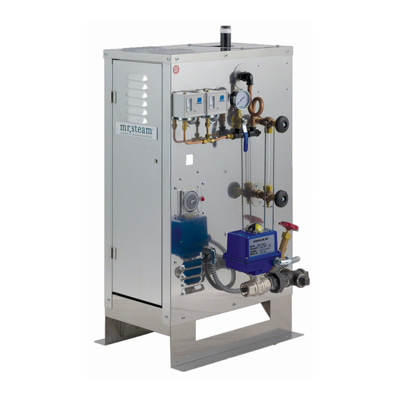
Page 31: Typical Component Arrangement Cu 360 - Cu 1400
steam ® CU Series Installation, Operating & Maintenance Manual _________________________________________________________________ CU 360-CU 1400 Typical Component Arrangement High Limit Operating Pressure Control Pressure Control Steam Outlet Terminal Block Data Plate Pressure Gauge Contactors Gauge Glass ON/OFF Switch Blank for Blow Down Timer Heating Elements Motorized Drain Valve... - Page 32 steam ® CU Series Installation, Operating & Maintenance Manual _________________________________________________________________ CU 2000-4500 with F1 Plus, Clock and Blowdown Operating Pressure Pressure Hi-Limit Control Terminal Relief Valve Pressure Block Control Steam Outlet Pressure Gauge Data Plate Fuses Liquid Level Control Contactor Gauge Glass 24hr/7day Blowdown Clock...
-
Page 33: Typical Component Arrangement Cu 2000 - Cu 4500
steam ® CU Series Installation, Operating & Maintenance Manual _________________________________________________________________ Commercial Steambath Replacement Parts Models CU 360 – CU 4500 _______________________________________ PART # DESCRIPTION ELECTRIC (cont..) _______________________________________ ______________________________________________ 99348 AUX LWCO RESET BUTTON BLOWDOWN ______________________________________________ _______________________________________ 99315 FUSE BLOCK 208/240V ______________________________________________ 99353 TIME DELAY RELAY BOARD... - Page 34 steam ® CU Series Installation, Operating & Maintenance Manual _________________________________________________________________ Commercial Steambath Replacement Parts (cont.) Models CU 360 – CU 4500 __________________________________________________ PART # DESCRIPTION __________________________________________________ WATER FEED & STEAM SOLENOIDS __________________________________________________ 99031 1/2" 120V CU1000-1400 (SN beginning with "N") CU2000-CU4500 (all) __________________________________________________ 99032...
Need help?
Do you have a question about the CU-360 and is the answer not in the manual?
Questions and answers