mr. steam CU-360 Installation, Operation & Maintenance Manual
Cu series
Hide thumbs
Also See for CU-360:
- Installation, operation & maintenance manual (36 pages) ,
- Installation instructions manual (6 pages) ,
- Installation, operation & maintenance manual (34 pages)
Table of Contents
Advertisement
CU Series Steambath Generators
Installation, Operation & Maintenance Manual
Models: CU-360 through CU-4500
_________________________________________
IMPORTANT: LEAVE THIS MANUAL WITH THE OWNER/OPERATOR
_________________________________________
Before Installing . . . . . . . . . . . . . . . . . . . . . . . .2
Table of Contents
Steam Room Guidelines . . . . . . . . . . . . . . . . . .2
Locating the Steambath Generator . . . . . . . . . . . .3
Drain, Safety Valve . . . . . . . . . . . . . . . . . . . .6
Water Quality Information . . . . . . . . . . . . . . . . . .6
Steam Room Guidelines . . . . . . . . . . . . . . . . . . .7
Steam Head & Acrylic Shield . . . . . . . . . . . . . . .7
Electric . . . . . . . . . . . . . . . . . . . . . . . . . . . . . .8
Wiring . . . . . . . . . . . . . . . . . . . . . . . . . . . . . .9
Control Circuit Wiring Diagrams . . . . . . . . .10-13
Digital 1 Control: Contents . . . . . . . . . . . . . . . .14
Control Installation . . . . . . . . . . . . . . . . . . .15
Temperature Sensor Installation . . . . . . . . . . .16
Contents . . . . . . . . . . . . . . . . . . . . . . . . . .16
Installation . . . . . . . . . . . . . . . . . . . . . . . . .17
Auxiliary Manual Reset Low Water Cutoff . . . . . .18
Principles of Operation . . . . . . . . . . . . . . . . . . .19
Operating and Testing
Automatic Blowdown, Digital 1 Control, CU-HL
Warning Signage . . . . . . . . . . . . . . . . . . . . . .21
Pre-Operation Check . . . . . . . . . . . . . . . . . . . .21
Manual Blowdown Instructions . . . . . . . . . . . .22
Maintenance Instructions . . . . . . . . . . . . . . . . . .23
Water Gauge & Gauge Glass: Installation . . . . . . .24
Water Gauge & Gauge Glass: Use and Care . . . . .25
24-hour and 7-day Time Switches . . . . . . . . . . . .25
Trouble Shooting . . . . . . . . . . . . . . . . . . . . . . .26
Digital 1 Control, Heating Element . . . . . . . . .27
Element Replacement Instructions . . . . . . . . . . .28
CU 360-CU 1400 . . . . . . . . . . . . . . . . . . . .29
CU 2000-CU4500 . . . . . . . . . . . . . . . . . . .30
Replacement Parts List . . . . . . . . . . . . . . . .31-32
.
mr
steam
43-20 34th Street
®
Long Island City, NY 11101
®
Sussman-Automatic Corp
info@mrsteam.com
TEL
www.mrsteam.com
FAX
. . . . . . .4
. . . . . . . . . . .5
. .20
. . . . . . . .22
9410 S. La Cienega Blvd.
Inglewood CA 90301
: 800 76 STEAM
TEL
: 718 472 3256
FAX
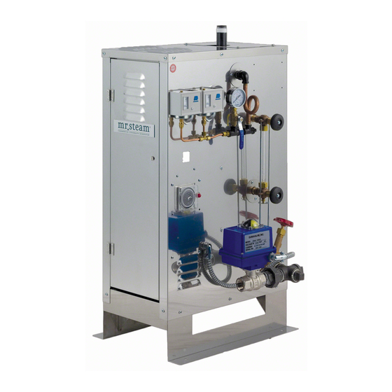
Typical CU Series Steambath Generator
(for illustrative purposes only)
IMPORTANT NOTE: As you follow these instructions,
you will notice warning and caution symbols. This infor-
mation is important for the safe and efficient installation
and operation of this generator. These are types of poten-
tial hazards that may occur during this installation and
operation:
states a hazard may cause serious injury or
death if precautions are not followed.
C A U T I O N
signals a situation where minor injury or
product damage may occur if you do not follow instructions.
WA R N I N G
: 800 72 STEAM
: 310 216 2944
1
PUR 100376 11/10
Advertisement
Table of Contents

Related Manuals for mr. steam CU-360


Summary of Contents for mr. steam CU-360
-
Page 1: Table Of Contents
CU Series Steambath Generators Installation, Operation & Maintenance Manual Models: CU-360 through CU-4500 _________________________________________ IMPORTANT: LEAVE THIS MANUAL WITH THE OWNER/OPERATOR _________________________________________ Before Installing ......2 Table of Contents Steam Room Guidelines . -
Page 2: Before Installing
Before Installing IMPORTANT: Take time to read these instructions thoroughly before installing or servicing. Although this CU Steambath Generator has been qualified for shipment by Mr. Steam, the following must be reviewed for proper and safe use. 1. Verify that the model and accessories are as specified and 6. -
Page 3: Locating The Steambath Generator
GENERAL PUBLIC IS STRONGLY RECOMMENDED. the steam room. Reference “Dimensional & Clearance Specifications” information on page 4. See page 5 for guidance if generator is more than 25 feet from steam room. Mr. Steam Installation For Illustrative Purposes Only Steam Generator 1" Steam... -
Page 4: Dimensional & Clearance Specifications
E L 1" from left side of CU generator. E R 16" from right side of CU generator. F Type of flooring: “C", suitable for combustible flooring. 4. For ease of servicing, Mr. Steam recommends a minimum of 36 inches of clearance all around the CU generator. -
Page 5: Selecting The Steambath Generator
Coast: 1-800-767-8326 or West Coast: 1-800-727-8326. Example: A steam room 8' x 9' x 8' = 576 Cu. Ft.(volume). Select the Mr. Steam Model which is the next larger volume. D. IMPORTANT: When specifying a CU Commercial In this example, Model CU-750 is the correct selection. -
Page 6: Installation: Plumbing, Water Supply, Steam Line, Drain, Safety Valve
steam ® CU Series Installation, Operating & Maintenance Manual Installation Plumbing All plumbing shall be performed by a qualified 1. The Digital 1 steam solenoid valve should be plumbed as close as Steam Line licensed plumber and in accordance with applicable practical to the steam room using only brass pipe or copper tubing National and local Codes. -
Page 7: Steam Room Guidelines
Acrylic Sheild steamhead. Fully Assembled IMPORTANT: Do not use with water soluble fragrance or fragrance containing emulsifiers or aldehydes. Acrylic Shield damage may result. Mr. Steam oils are approved for use with this acrylic shield. Diagram B... -
Page 8: Electric
20 in-lbs.). Model No. AMPERAGE CHART 208V/1 PH 208V/3 PH 240V/1 PH 240V/3 PH 480V/3 PH 600V/3 - Indicates Total Ampere Draw of Specific CU Model at Voltage & Phase Specified ________________________________________________________________________________________ CU-360 ________________________________________________________________________________________ CU-500 ________________________________________________________________________________________ CU-750 ________________________________________________________________________________________ CU-1000 ________________________________________________________________________________________ CU-1250... -
Page 9: Wiring
steam ® CU Series Installation, Operating & Maintenance Manual Wiring 3. IMPORTANT: Insure all electrical connections are sufficiently tightened prior to energizing generator. C A U T I O N To avoid possible electric shock, the See Page 8, Item 5. steambath generator shall be suitably grounded in accor- dance with National Electric and local Codes. -
Page 10: Control Circuit Wiring Diagrams
steam ® CU Series Installation, Operating & Maintenance Manual Control Circuit Wiring Diagram SEE PAGES 11, 12 & 13 FOR DIAGRAMS Installer shall use a safety switch of adequate capacity employing suit- C A U T I O N ably rated circuit breakers or fuses between main electrical power source(s) and the generator. -
Page 11: Control Circuit Wiring Diagrams
steam ® CU Series Installation, Operating & Maintenance Manual Control Circuit Wiring Diagram Digital 1 Temperature Control System and optional automatic blowdown assembly For Models: CU-360A to CU-750A and CU-1000AF3, CU-1250AF3, CU-1400AF3 LEGEND ___________ Factory Wiring __ __ __ __ __ Field Wiring 1. - Page 12 steam ® CU Series Installation, Operating & Maintenance Manual Control Circuit Wiring Diagram Digital 1 Temperature Control System and optional automatic blowdown assembly For Models: CU-1000AB3, CU-1000AC3, CU-1250AB3, CU-1250AC3, CU-1400AB3, CU-1400AC3 LEGEND ___________ Factory Wiring __ __ __ __ __ Field Wiring 1.
- Page 13 steam ® CU Series Installation, Operating & Maintenance Manual Control Circuit Wiring Diagram Models CU-2000 and higher with Digital 1 Temperature Control System and Optional Automatic Blowdown Assembly AUXILIARY LOW WATER CUTOFF 90241MRT 1. Digital 1 Plus sensors are intended to be field installed within the steam IMPORTANT: room at the location selected by the designer/architect.
-
Page 14: Digital 1 Control: Contents
Installation, Operating & Maintenance Manual DIGITAL 1 ™ Kit Contents Digital 1 Sensor Mr. Steam CU Steambath Generator can be used for Digital 1 Control and 30 ft. Cable Acrylic Shield one or two steam rooms in accordance with Page 5, Item D. -
Page 15: Control Installation
steam ® CU Series Installation, Operating & Maintenance Manual Digital 1 Control Installation ™ NOTE: If the stam generator came with a factory installed Digital 1control skip to page 16. WA R N I N G Hazard of Electric Shock. Disconnect all power supplies before making wiring connections. -
Page 16: Temperature Sensor Installation
steam ® CU Series Installation, Operating & Maintenance Manual Digital 1 ™ Operating Temperature Sensor Installation • Locate sensor on a wall inside the steam room five (5) feet above the floor. DO NOT LOCATE THE DIGITAL 1 SENSORS NEAR OR ABOVE THE STEAMHEAD(S) AS THIS MAY CAUSE DIRECT •... -
Page 17: Installation
steam ® CU Series Installation, Operating & Maintenance Manual Automatic Blowdown System Kit Installation Note: If the steam generator came with a factory installed Automatic Blowdown System see page 22 on how to program the timer. Terminal Block in Steam Generator WA R N I N G Hazard of Electric Shock. - Page 18 steam ® CU Series Installation, Operating & Maintenance Manual 30 Minute Room Timer The 30 minute timer provides guests in the steam room an accu- Steam Vents rate and easy way to safely time their steam sessions. It is avail- able as a Digital (CU-99216DIG) or Mechanical (CU-99216B) Steam Vent timer.
-
Page 19: Auxiliary Manual Reset Low Water Cutoff
A lighted taining the set pressure. As the water level in the generator ON/OFF switch activates the control circuit. MR. STEAM decreases, the liquid level control will energize the water CU Generators are equipped with automatic liquid level/low solenoid valve on and off and maintain proper water level. - Page 20 5. Turn the override switch to automatic ( room reaches normal operating range. NOTE: ASME blowdown separator tank systems are available from Mr. Steam. For more information please contact Under normal operation, the actual room temperature will be Message Display Mr.
-
Page 21: Warning Signage
steam ® CU Series Installation, Operating & Maintenance Manual Warning Signage The CU Steambath generator is provided with a WARNING sign. This WARNING is to be secured to the outside of the steam room, on the steamroom door or adjacent to that door. 1. -
Page 22: Operation
Consult with a licensed plumber. access door. NOTE: ASME blowdown separator tank systems are available Use of chemical cleaning compounds from Mr. Steam. For more information please contact Mr. Steam voids warranty. C A U T I O N at 1-800-76 STEAM. -
Page 23: Maintenance Instructions
steam ® CU Series Installation, Operating & Maintenance Manual Maintenance Instructions 4. Generators equipped with level probes (Models CU 2000 - CU 1400) for maintaining operating water level and probe To establish a good preventive maintenance program, for auxiliary low water cut-off protection need special con- we suggest that the site equipment foreman, engineer sideration. -
Page 24: Water Gauge & Gauge Glass Installation
steam ® CU Series Installation, Operating & Maintenance Manual Water Gauge & Gauge Glass Installation Only properly trained personnel should install and maintain water gauge glass and connections. Pressure in genera- IMPORTANT: tor must be at zero before proceeding. Remember to wear safety Top Gauge gloves and glasses during installation. -
Page 25: Water Gauge & Gauge Glass Use And Care
steam ® CU Series Installation, Operating & Maintenance Manual Water Gauge & Gauge Glass 24-Hour and 7-day Time Switches NOTE: The Time Clock controls boiler operation. The boiler Use and Care is on when the timer is on. The Blowdown Valve will open DO NOTs when the Timer turns the Boiler off. -
Page 26: Trouble Shooting
steam ® CU Series Installation, Operating & Maintenance Manual Trouble Shooting To prevent risk of electric shock, trouble shooting should be done only by a qualified licensed electrician C A U T I O N _________________________________________________________________________________________________________ Problem Probable Cause Suggested Remedy No water in generator Water supply is "OFF"... -
Page 27: Check
1. Check power voltage across heating element terminals. High Water Cutout Probes Refer to nameplate data for voltage rating. Models CU-360 through CU-1400 are equipped with two Voltage should be as marked on nameplate. probes for low water cut-off (LWCO) and water feed con- 2. -
Page 28: Element Replacement Instructions
steam ® CU Series Installation, Operating & Maintenance Manual Instructions for Element Replacement READ INSTRUCTIONS COMPLETELY BEFORE STARTING WORK Before Installing your new elements be sure McDonnell Miller low water cut-off and aux. low water cutoff (if C A U T I O N supplied) is operating properly. -
Page 29: Typical Component Arrangement Cu 360-Cu 1400
steam ® CU Series Installation, Operating & Maintenance Manual CU 360-CU 1400 Typical Component Arrangement Hi-Limit Operating Pressure Pressure Control Control Steam Outlet Terminal Block Data Plate Pressure Gauge Contactors Gauge Glass On/Off Switch 24hr/7day Blowdown Clock Heating Elements Motorized Drain Valve For Illustrative Purposes Only. -
Page 30: Cu 2000-Cu4500
steam ® CU Series Installation, Operating & Maintenance Manual CU 2000-4500 with Digital 1, Clock and Blowdown Hi-Limit Operating Pressure Pressure Pressure Control Terminal Relief Valve Control Block Steam Outlet Pressure Gauge Data Plate Float-type Fuses Liquid Level Control Contactor Gauge Glass 24hr/7day AutoFlush... -
Page 31: Replacement Parts List
steam ® CU Series Installation, Operating & Maintenance Manual Models CU 360 – CU 4500 Commercial Steambath Replacement Parts ____________________________________________ ELECTRIC (cont.) _________________________________________________ 99348 AUX LWCO RESET BUTTON ____________________________________________ _________________________________________________ 99315 Fuse Block 208/240V ____________________________________________ _________________________________________________ PART # DESCRIPTION 99314 Power Fuses 208/240V 60A 250V 99353 Time Delay Relay Board... - Page 32 steam ® CU Series Installation, Operating & Maintenance Manual Models CU 360 – CU 4500 __________________________________________________ Commercial Steambath Replacement Parts __________________________________________________ __________________________________________________ PART # DESCRIPTION ⁄ 99031 " 120V WATER FEED & STEAM SOLENOIDS CU1000-CU1400 (SN beginning with "N") CU2000-CU4500 (all) __________________________________________________ ⁄...
Need help?
Do you have a question about the CU-360 and is the answer not in the manual?
Questions and answers