Table of Contents
Advertisement
Advertisement
Table of Contents

Subscribe to Our Youtube Channel
Related Manuals for Oerlikon MAG W 300 P


Summary of Contents for Oerlikon MAG W 300 P
- Page 1 MAG W 300 to 700 MAG.DRIVE S Turbomolecular Pumps with Magnetic Bearing and Frequency Converter Incorporation Declaration & Operating Instructions 17200045_002_A3 Part Nos. 410300Vxxxx 410400Vxxxx 410600Vxxxx 410700Vxxxx and pumps modified by Oerlikon Leybold Vacuum...
-
Page 2: Table Of Contents
Connect purge gas or a venting valve Electrical connection for the integrated frequency converter Separating the frequency converter from the pump Electrical connection for the separate frequency converter 3.10 Relays, LEDs, PLC Interface 17200045_002_A3 - 04/2014 - © Oerlikon Leybold Vacuum... - Page 3 Error messages 4.8.2 Warning messages Maintenance Cleaning Changing the touch-down bearings Oerlikon Leybold Vacuum Service Troubleshooting Waste Disposal Certificates EC Incorporation Declaration EC Declaration of Conformity Index Original installation and operating instructions. 17200045_002_A3 - 04/2014 - © Oerlikon Leybold Vacuum...
- Page 4 Operating Instructions and follow the information so as to ensure optimum and safe working right from the start. The Oerlikon Leybold Vacuum MAG W 300 to W 700 have been designed for safe and efficient operation when used properly and in accordance with these Operating Instructions.
-
Page 5: Important Safety Information
To avoid the destruction of the equipment and to prevent injuries of the operating staff the leading European manufacturers of vacuum pumps strictly recommend to follow the installation instructions as given in this manual. 17200045_002_A3 - 04/2014 - © Oerlikon Leybold Vacuum... -
Page 6: Electrical Hazards
When applying external voltages above 42 V to the connection termi- nals, observe the applicable VDE safety regulations! Make the electrical connections only after pump and accessories (e.g. air cooler) have been installed mechanically 17200045_002_A3 - 04/2014 - © Oerlikon Leybold Vacuum... -
Page 7: Thermal Hazards
Contaminated parts can be detrimental to health and environment. Before beginning with any work, first find out whether any parts are contaminated. Adhere to the relevant regulations and take the neces- sary precautions when handling contaminated parts. 17200045_002_A3 - 04/2014 - © Oerlikon Leybold Vacuum... -
Page 8: Danger Of Ignition
Dangers in connection with safety-related measures and precautions CAUTION The frequency converter is not equipped with its own emergency shut down switch. Such a facility needs to be provided from the side of the system. 17200045_002_A3 - 04/2014 - © Oerlikon Leybold Vacuum... -
Page 9: Risk Of Damaging The Pump
In the case of critical applications you must consult our Applications Dept. first. Pressures given in bar or mbar are absolute values. If exceptionally a gauge pressure is meant, a “g” is added (bar(g)). 17200045_002_A3 - 04/2014 - © Oerlikon Leybold Vacuum... -
Page 10: Description
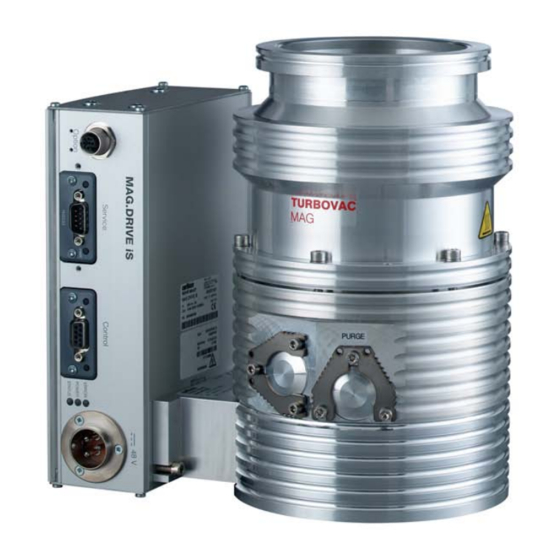
Description Description The Oerlikon Leybold Vacuum MAG pumping system consists of: The MAG turbo pump ■ The MAG are turbomolecular pumps uti li zing magnetic bearings.They are designed to evacuate va cuum chambers down to pressure values in the high-vacuum range. - Page 11 Description MAG W 600 iP with DN 160 flange MAG W 300 iP with DN 100 flange MAG W 400 P with DN 160 flange MAG.DRIVE S Fig. 1.1 MAG models 17200045_002_A3 - 04/2014 - © Oerlikon Leybold Vacuum...
-
Page 12: Design And Function
They are only used in case of the breaking of the power supply or internal cables during operation, strong shocks, or faulty electronics. The MAG has a purge gas device. A controlled synchronous motor is used to power the rotor. 17200045_002_A3 - 04/2014 - © Oerlikon Leybold Vacuum... -
Page 13: Supplied Equipment
The frequency converter has the following interfaces: a control interface (24 V PLC), ■ an interface for the Oerlikon Leybold Vacuum Service (RS 232) and ■ a connection for optional accessories, e.g. an air cooler. ■... -
Page 14: Technical Data
TRIVAC Run-up time < 6 min Forevacuum flange DN 25 KF (clamp shoe) Purge gas / venting flange DN 16 KF (clamp shoe) Optional cooling connection G 1/8” Weight, approx. 17 kg 17200045_002_A3 - 04/2014 - © Oerlikon Leybold Vacuum... - Page 15 High-vacuum pressure Fig. 1.3 Pumping speed curves for Nitrogen MAG W 700 MAG W 600 MAG W 400 MAG W 300 mbar Hochvakuumdruck High-vacuum pressure Fig. 1.4 Pumping speed curves for Hydrogen 17200045_002_A3 - 04/2014 - © Oerlikon Leybold Vacuum...
- Page 16 Description MAG W 300 & 400, N mbar Forevacuum pressure Vorvakuumdruck MAG W 600 & 700, N mbar Vorvakuumdruck Forevacuum pressure Fig. 1.5 Compression curves for Nitrogen 17200045_002_A3 - 04/2014 - © Oerlikon Leybold Vacuum...
- Page 17 Description MAG W 300 & 400, H mbar Forevacuum pressure Vorvakuumdruck MAG W 600 & 700, H mbar Forevacuum pressure Vorvakuumdruck Fig. 1.6 Compression curves for Hydrogen 17200045_002_A3 - 04/2014 - © Oerlikon Leybold Vacuum...
- Page 18 (Cw 20 °C, 60 l/h) (KW 20 °C, 60 l/h) Luftkühlung Air cooling Umgebungstemperatur 25 °C Ambient temperature 25 °C Konvektion Convection mbar Druck Pressure Fig. 1.7 Throughput curves for Nitrogen 17200045_002_A3 - 04/2014 - © Oerlikon Leybold Vacuum...
- Page 19 Umgebungstemperatur 25 °C Ambient temperature 25 °C Wasserkühlung (KW 20 °C, 60 l/h) Water cooling (Cw 20 °C, 60 l/h) Luftkühlung Air cooling Konvektion Convection mbar Pressure Druck Fig. 1.8 Throughput curves for Argon 17200045_002_A3 - 04/2014 - © Oerlikon Leybold Vacuum...
- Page 20 DRIVE/BEARING cable connected instead of MAG.DRIVE iS Fig. 1.9 Dimensional drawing of the pumps, dimensions in mm Space for DRIVE/BEARING cable (Frontplatte) (Front Panel) Fig. 1.10 Dimensional drawing of the MAG.DRIVE S, dimensions in mm 17200045_002_A3 - 04/2014 - © Oerlikon Leybold Vacuum...
- Page 21 Storage temperature - 10 °C to + 60 °C Relative air humidity 95% (non condensing) Overvoltage category Contamination level in accordance with EN 61010 Weight 6.5 kg Degree of protection (EN 60529) IP30 17200045_002_A3 - 04/2014 - © Oerlikon Leybold Vacuum...
-
Page 22: Ordering Data
MAG W 600 iP DN 160 ISO-K 410600V0505 MAG W 600 iP DN 160 CF 410600V0506 MAG W 700 iP DN 200 ISO-K 410700V0505 MAG W 700 iP DN 200 CF 410700V0506 17200045_002_A3 - 04/2014 - © Oerlikon Leybold Vacuum... - Page 23 410300V0101 Water cooling MAG W 600/700 410600V0101 Air cooling MAG W 300/400 410300V0102 Air cooling MAG W 600/700 410600V0102 Interface module RS 232 module 410300V0902 RS 485 module 410300V0903 Profibus module 410300V0904 17200045_002_A3 - 04/2014 - © Oerlikon Leybold Vacuum...
-
Page 24: Accessories
E 200 17 195 DN 160 ISO-K E 200 00 307 DN 160 CF 200 17 247 DN 200 ISO-K on request DN 200 CF on request Microfilter, DN 100 ISO-K 887 21 17200045_002_A3 - 04/2014 - © Oerlikon Leybold Vacuum... - Page 25 DN 16/25, 40 mm, Al 183 86 Mindestabstand für Belüftung Minimum distance for cooling air Ansicht von oben Top view Fig. 1.12 Dimensional drawing for the power supply TURBO.POWER 500; dimensions in mm 17200045_002_A3 - 04/2014 - © Oerlikon Leybold Vacuum...
-
Page 26: Transport And Storing
Keep the packaging Make sure that the product has not been damaged during transportation. If this unit is damaged contact your carrier and inform Oerlikon Leybold Vacuum if necessary. To prevent damages to the pump, use the packaging pro vided for storage and transport. -
Page 27: Installation
Both pump and frequency converter are intended for being operated within closed rooms. The use of any accessories which have not been specified by Oerlikon Leybold Vacuum is only allowed after approval by Oerlikon Leybold Vacuum. The integrated MAG.DRIVE iS or the separate MAG.DRIVE S frequency con- verter will be required for the operation of the turbomolecular pump. - Page 28 Conversions, manipulations and maintenance work by personnel not ■ authorised by Oerlikon Leybold Vacuum. Any non-conforming utilisation of pump, frequency converter and accesso- WARNING ries can result in severe injury and cause damage to components. 17200045_002_A3 - 04/2014 - © Oerlikon Leybold Vacuum...
-
Page 29: Operating Environment
Places of installation without restrictions. At altitudes over 1000 m heat dissipation by the ambient air is impaired. Please consult us. The frequency converter must not be operated in explosive gas atmo spheres. 17200045_002_A3 - 04/2014 - © Oerlikon Leybold Vacuum... -
Page 30: Attach The Pump To The Vacuum Chamber
900 Nm for MAG 300/400 and up to 3500 Nm for MAG 600/700 will have to be absorbed by the system. In most applications the pump is flanged to the high-vacuum flange at the apparatus. The pump can be mounted and operated in any desired attitude. 17200045_002_A3 - 04/2014 - © Oerlikon Leybold Vacuum... - Page 31 The turbomolecular pump runs low in vibration and noise. No vibrations or resonances from outside equipment may be allowed to be transferred to the turbomolecular pump. The turbomolecular pump is sensitive to low-frequency vibrations. 17200045_002_A3 - 04/2014 - © Oerlikon Leybold Vacuum...
- Page 32 If several turbomolecular pumps are installed to the vacuum chamber of the Vibration influence same system, there is the risk of interference (vibration interference between the pumps). If such a risk exists please contact Oerlikon Leybold Vacuum Application Support. The standard pump fixing is sufficient for earthquake protection. If required fix the system to the bottom or to the walls.
- Page 33 When using collar flanges or claws for mounting the MAG W 600, the WARNING pump may twist should the rotor suddenly seize. 17200045_002_A3 - 04/2014 - © Oerlikon Leybold Vacuum...
- Page 34 M8x35 M10x45 M10x45 M10x45 Bolt quality 8.8 or 8.8 or 8.8 or 8.8 or stainless steel bolts A2(A4)-70 A2(A4)-80 A2(A4)-80 A2(A4)-80 Fastening torque Fig. 3.4 Mounting high vacuum flange ISO-K. 17200045_002_A3 - 04/2014 - © Oerlikon Leybold Vacuum...
- Page 35 During operation the pump can get so hot that there is the risk of suffer ing CAUTION burns (up to approximately 120 °C). Protect the hot parts against being touched. 17200045_002_A3 - 04/2014 - © Oerlikon Leybold Vacuum...
- Page 36 12 mm Recommended bolt for steel flanges DIN 835, M8x30 M8x30 M8x30 M8x35 L2 = Bolt quality 8.8 or stainless steel bolts A2(A4)-70 Fastening torque Fig. 3.6 Mounting high vacuum flange CF. 17200045_002_A3 - 04/2014 - © Oerlikon Leybold Vacuum...
-
Page 37: Forevacuum Connection
Alternatively purge the forevacuum line with inert gas. In this case the pressure in the forevacuum line must be over 10 mbar 17200045_002_A3 - 04/2014 - © Oerlikon Leybold Vacuum... - Page 38 Ensure that the pump is sufficiently isolated against vibrations generated by the forevacuum pump. No forces from the piping system may be allowed to affect the turbomolecu- lar pump. Support the piping correspondingly or decouple through flexible joints. 17200045_002_A3 - 04/2014 - © Oerlikon Leybold Vacuum...
-
Page 39: Connecting The Cooling
High gas throughput, cyclic operation or high ambient temperatures for pumps with a CF flange Pumping of argon Air or water cooling can be mounted to the pump; see Section 1.4 Ordering Data. 17200045_002_A3 - 04/2014 - © Oerlikon Leybold Vacuum... -
Page 40: Water Quality
Manganese < 0.1 mg/l Ammonium < 1.0 mg/l Free chlorine < 0.2 mg/l 8 °dH (degrees German hardness) = 1.4mmol/l = 10 °e (degrees English hardness) = 14 °f (degrees French hardness) 17200045_002_A3 - 04/2014 - © Oerlikon Leybold Vacuum... - Page 41 Turn off the cooling water supply before venting the turbomolecular pump Avoid condensate formation and when it is not running in order to avoid condensate formation in the pump. 17200045_002_A3 - 04/2014 - © Oerlikon Leybold Vacuum...
- Page 42 If you do not close the cooling water it may take longer to achieve ultimate pressu- re after start up of the system. 17200045_002_A3 - 04/2014 - © Oerlikon Leybold Vacuum...
-
Page 43: Connect Purge Gas Or A Venting Valve
We recommend a purge gas flow of 0.4 mbar·l/s (24 sccm) with Nitrogen. The pressure in the pump must not exceed 1400 mbar (0.4 bar over- WARNING pressure). Observe Safety Informations 0.1.2 to 0.1.5. 17200045_002_A3 - 04/2014 - © Oerlikon Leybold Vacuum... -
Page 44: Electrical Connection For The Integrated Frequency Converter
POWER 500 power supply. If you use another power supply, it must have a current limiter or fuse which limits the maximum current to 10 Amps or another suitable current limitation element. 17200045_002_A3 - 04/2014 - © Oerlikon Leybold Vacuum... - Page 45 Fig. 3.16 Reqired pin assignment of the 3 pole connector model Hirose HS21P-3; view from the soldered side Ensure correct polarity; see Fig. 3.16. Pin 1 + 48 VDC Pin 2 Pin 3 Connect the power supply to the mains. 17200045_002_A3 - 04/2014 - © Oerlikon Leybold Vacuum...
-
Page 46: Separating The Frequency Converter From The Pump
40 °C (104 °F). During operation the frequency converter may attain temperatures up to CAUTION 75 °C. We recommend that the unit be installed so that it can not be touched inadvertently. 17200045_002_A3 - 04/2014 - © Oerlikon Leybold Vacuum... -
Page 47: Electrical Connection For The Separate Frequency Converter
* PLC = Programmable Logic Control Ground bolt Fig. 3.17 Front and rear view of the separate frequency converter Electrical connection for the separate frequency converter Observe Safety Informations 0.2 DANGER 17200045_002_A3 - 04/2014 - © Oerlikon Leybold Vacuum... - Page 48 Disconnect and connect the cable connections only while the pump is turning no longer (green status LED off) and with the mains power switched off (yellow power LED off). Otherwise there is the risk of damaging the pump or the frequency converter. 17200045_002_A3 - 04/2014 - © Oerlikon Leybold Vacuum...
- Page 49 Insert and fasten the DRIVE/BEARING cable. On the converter side the fastener must click. Connect the frequency converter using the ground bolt to the protective WARNING ground system. Connect the frequency converter to the mains.. 17200045_002_A3 - 04/2014 - © Oerlikon Leybold Vacuum...
-
Page 50: Relays, Leds, Plc Interface
(0.3 s): Start delay active Normal operation Yellow LED PWR and green LED STS (flash fast Running down, brake operation at n < 100 Hz alternately i.e. venting is possible: option) 17200045_002_A3 - 04/2014 - © Oerlikon Leybold Vacuum... - Page 51 1.8 kΩ MAG 300 3.3 kΩ Example 2: Operation via contacts Contact open = STOP MAG 300 Contact closed = START 12-15 V MAG 300 Fig.3.20 Pin assignment of the CONTROL connector 17200045_002_A3 - 04/2014 - © Oerlikon Leybold Vacuum...
-
Page 52: Operation
In individual cases and after consultation also dry, filtered, oil-free air or fil- tered ambient air may be used (filter mesh < 1µm). Change the filters after some time, at least annually. 17200045_002_A3 - 04/2014 - © Oerlikon Leybold Vacuum... -
Page 53: Interfaces
Before making any connections switch the pump off and wait until it turns NOTICE no longer. Then deenergise the frequency converter. Before inserting the module, ensure that the affixing screws have been fully loosened. 17200045_002_A3 - 04/2014 - © Oerlikon Leybold Vacuum... -
Page 54: Specific Parameter Data For The Pumps
°C °C °C °C P18 / P24 P131 P133 P126 MAG W 300/400 MAG W 600/700 17200045_002_A3 - 04/2014 - © Oerlikon Leybold Vacuum... -
Page 55: Switching On
Do not suddenly expose the MAG to an already evacuated vacuum cham- ■ ber. The pressure surge may cause the rotor to make contact with the touch-down bearings. This will cause increased wear. 17200045_002_A3 - 04/2014 - © Oerlikon Leybold Vacuum... -
Page 56: Bakeout
At speeds approximately below 200 Hz, there will not be enough power CAUTION any more for the LEDs, i.e. the pump may still turn with out any of the LEDs being on. Switch off the forevacuum pump. 17200045_002_A3 - 04/2014 - © Oerlikon Leybold Vacuum... - Page 57 In the case of an emergency shut down, the pump is switched off as de scribed above. The rotor of the turbomolecular pump may be stopped faster by controlled venting the pump, see Fig. 4.4. 17200045_002_A3 - 04/2014 - © Oerlikon Leybold Vacuum...
-
Page 58: Venting
The slower the pump is vented, the longer the service life of the bearings will be. The pump must not be vented to pressures above atmospheric pressure. 17200045_002_A3 - 04/2014 - © Oerlikon Leybold Vacuum... -
Page 59: Removing The Pump From The System
Pack the pump so that it cannot be damaged during shipping and storage. Pay particular attention to protection for the flanges and the electrical plug. Observe the instructions in Section 5.3 if you forward the pump to Oerlikon Leybold Vacuum. -
Page 60: Display
The display can be set to four different languages: English, German, Chinese and Japanese. For English and German it has 6 lines, for Chinese and Japanese 4. Function buttons Fig. 4.6 MAG.DRIVE S with English display Fig. 4.7 MAG.DRIVE S with Japanese display 17200045_002_A3 - 04/2014 - © Oerlikon Leybold Vacuum... - Page 61 Display 17200045_002_A3 - 04/2014 - © Oerlikon Leybold Vacuum...
- Page 62 Display 17200045_002_A3 - 04/2014 - © Oerlikon Leybold Vacuum...
- Page 63 Display 17200045_002_A3 - 04/2014 - © Oerlikon Leybold Vacuum...
- Page 64 = Magnet bearing current [A] Start cnt = Number of start/stop cycles Pump op. = Actual pump operation time [h] Standby cnt = Number of standby/normal cycles Pump type = Pump type 17200045_002_A3 - 04/2014 - © Oerlikon Leybold Vacuum...
- Page 65 Up/Down keys you can choose the main menu item, see also menu structure table Main menu Drive status Identification Service Prog. pump Enter Main menu Prog. pump Prog. conv. Storing data Keypad Enter 17200045_002_A3 - 04/2014 - © Oerlikon Leybold Vacuum...
- Page 66 Storing data Menu Activate Pressing the “Activate” button will store all data to the pump EEPROM. Important: Do not interrupt this procedure (power OFF) as long as the LED lights are flashing. 17200045_002_A3 - 04/2014 - © Oerlikon Leybold Vacuum...
- Page 67 Changing the setting of the standby speed is done in the same way as for the nominal speed setting. The standby setpoint needs to be adjusted bet- ween min. speed and max. nominal speed. Standby speed must be acti- vated through a serial or Fieldbus interface. 17200045_002_A3 - 04/2014 - © Oerlikon Leybold Vacuum...
- Page 68 24 V is enabled when logging data is true Vent valve 24 V for driving a venting valve Brake 48 V voltage enables the deceleration effect when the brake resistor has been connected 17200045_002_A3 - 04/2014 - © Oerlikon Leybold Vacuum...
- Page 69 0 = OFF to 3000sec. Front switches on/off ■ The front switches START and STOP may be enabled or disabled so as to prevent any inadvertent operation of these switches during operation via the interface. 17200045_002_A3 - 04/2014 - © Oerlikon Leybold Vacuum...
-
Page 70: Error Messages
OLV service. Time limit. Start->fmin Pump load too high, leakage failure Check forevacuum pressure, check leakage, check process conditions, remove foreign material from pump rotor, check converter, check pump, contact OLV service. 17200045_002_A3 - 04/2014 - © Oerlikon Leybold Vacuum... - Page 71 Fieldbus modules installed. Check installation of Fieldbus module Watchdog USS-Bus Cable connection to communication Check cable connection, check master functionality, module lost, master communication change converter, contact OLV service. was interrupted, interface defective. 17200045_002_A3 - 04/2014 - © Oerlikon Leybold Vacuum...
- Page 72 ON converter, change converter or pump if necessary Checksum converter-E. Converter failure, pump failure, Switch OFF pump, wait until pump rotor has cable failure stopped, power OFF / ON converter, change converter if necessary 17200045_002_A3 - 04/2014 - © Oerlikon Leybold Vacuum...
- Page 73 OFF / ON converter, change converter if necessary Guarding - Failure Transmit not send BUSOFF identified Failure CAN-BUS CAN open Initi. fail CAN open node err. CAN open guarding CAN open transmit prot. 17200045_002_A3 - 04/2014 - © Oerlikon Leybold Vacuum...
- Page 74 Init. motor safety module Fail number format Intern. para. access Init. of parameters User stack overflow Par. controller ini. Insp. assistance p. Exception failure Param. access layer Activ. assist. para. Runtime error 17200045_002_A3 - 04/2014 - © Oerlikon Leybold Vacuum...
-
Page 75: Warning Messages
Check mounting position of MAG 600/700, check external vibration level, change pump if necessary 8000H Bearing system overloaded (6) Check mounting position of MAG 600/700, check external vibration level, change pump if necessary. 17200045_002_A3 - 04/2014 - © Oerlikon Leybold Vacuum... - Page 76 Bearing clearance X5 2000H Aux. bearing contact numbers Check converter and cable, check mounting position of pump, check external vibration level, send pump to service. 4000H Aux. bearing contact time 8000H Bearing contact generator 17200045_002_A3 - 04/2014 - © Oerlikon Leybold Vacuum...
-
Page 77: Maintenance
Rotor exchange the latest. Such maintenance work can only be done by the Oerlikon Leybold Vacuum Service. If required contact the Oerlikon Leybold Vacuum service center nearest to your location. You can find the address on our internet page www. -
Page 78: Changing The Touch-Down Bearings
(def- ault 1000 contacts or 1 hour). In this case maintenance is required. Only the Oerlikon Leybold Vacuum service can change the touch-down bear- ings. Oerlikon Leybold Vacuum Service Whenever you send us in equipment, indicate whether the equipment is con- taminated or is free of substances which could pose a health hazard. -
Page 79: Troubleshooting
Check cables and power supply. Operator/ not on. maintenance staff DC power miswired. Ensure correct polarity of the DC cable. Maintenance staff Frequency converter defective. Replace frequency converter. Maintenance staff/ OLV service 17200045_002_A3 - 04/2014 - © Oerlikon Leybold Vacuum... - Page 80 Check the ultimate pressure of the back- Operator/ pumping speed or ultimate pressure ing pump and install a higher capacity maintenance staff which is too high. vacuum pump if necessary. Frequency parameters programmed Check parameters. OLV service wrongly. 17200045_002_A3 - 04/2014 - © Oerlikon Leybold Vacuum...
-
Page 81: Waste Disposal
Separate clean components according to their materials, and dispose of these accordingly. We offer this service. Further details are available on request. When sending us any equipment, observe the regulations given in Section “5.3 Oerlikon Leybold Vacuum service”. 17200045_002_A3 - 04/2014 - © Oerlikon Leybold Vacuum... -
Page 82: Certificates
This product has been tested to the requirements of CAN/ CSA-C22.2 No. 61010-1, third edition, including Amendment 1, or a later version of the same standard incorporating the same level of testing requirements. 17200045_002_A3 - 04/2014 - © Oerlikon Leybold Vacuum... -
Page 83: Ec Incorporation Declaration
EC Incorporation Declaration 17200045_002_A3 - 04/2014 - © Oerlikon Leybold Vacuum... -
Page 84: Ec Declaration Of Conformity
EC Declaration of Conformity 17200045_002_A3 - 04/2014 - © Oerlikon Leybold Vacuum... - Page 85 17200045_002_A3 - 04/2014 - © Oerlikon Leybold Vacuum...
- Page 86 17200045_002_A3 - 04/2014 - © Oerlikon Leybold Vacuum...
-
Page 87: Index
38 pressure rise 57, 58 function keys 64 Pumping speed curves 15 fuse 9, 21, 44, 47 purge gas 5, 7, 9, 12-14, 20, 22, 25, 27, 30, 43, 52, 58, 77 17200045_002_A3 - 04/2014 - © Oerlikon Leybold Vacuum... - Page 88 Oerlikon Leybold Vacuum America Oerlikon Leybold Vacuum France S.A.S. Japan Co., Ltd. Valence Factory Tsukuba Technical Service Center Oerlikon Leybold Vacuum GmbH 640, Rue A. Bergès 1959, Kami-yokoba Bonner Strasse 498 B.P. 107 Tsukuba-shi, Ibaraki D-50968 Cologne Oerlikon Leybold Vacuum F-26501 Bourg-lès-Valence Cedex...
Need help?
Do you have a question about the MAG W 300 P and is the answer not in the manual?
Questions and answers