Table of Contents

Subscribe to Our Youtube Channel
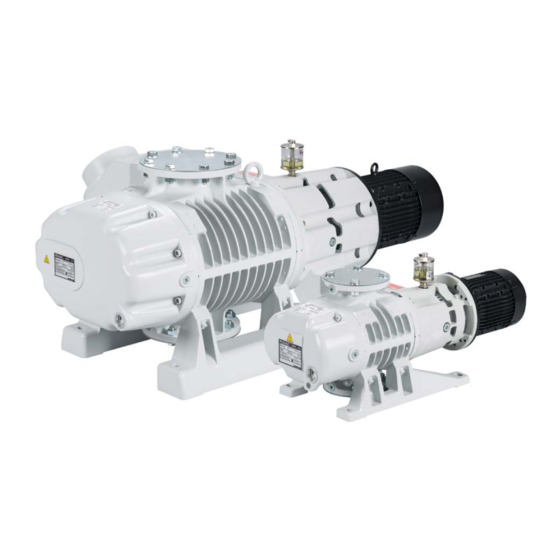
Related Manuals for Oerlikon RUVAC WA


Summary of Contents for Oerlikon RUVAC WA
- Page 1 RUVAC WA / WAU 251/501/1001/2001 Roots vacuum pumps ATEX Categories 3 i and 3 i/o Installation and Operating Instructions GA03107_002_A4 Part Numbers 112 17/54 113 22/42 117 20/21/24/30/31/34/40/41/44 /50/51 118 31/41/51 128 38 155 008/011V 167 004/022...
-
Page 2: Table Of Contents
1.1.4 Lubricants Standard Specification Technical Data 1.3.1 Motor Data Ordering data Transport and Storage Installation Installation 3.1.1 Filling in of the oil Conforming Utilisation 3.2.1 Non-conforming Utilisation Electrical Connection Connecting the Flanges GA03107_002_A4 - 09/2015 - © Oerlikon Leybold Vacuum... - Page 3 Exchanging the Bearings 5.10 Service at Oerlikon Leybold Vacuum 5.11 Maintenance Schedule Troubleshooting Wearing and Original Spare Parts Waste Disposal EC Declaration of Conformity EC Incorporation Declaration Original installation and operating instructions. GA03107_002_A4 - 09/2015 - © Oerlikon Leybold Vacuum...
- Page 4 Operating Instructions and follow the information so as to ensure optimum and safe working right from the start. The Oerlikon Leybold Vacuum RUVAC WA/WAU has been designed for safe and efficient operation when used properly and in accordance with these Operating Instructions.
-
Page 5: Important Safety Information
In order to prevent the destruction of equipment and injuries to the operating personnel, we urgently recommend to follow the installation instructions given in these Operating Instructions. GA03107_002_A4 - 09/2015 - © Oerlikon Leybold Vacuum... -
Page 6: Electrical Hazards
Safety Information The pumps must only be operated at the permitted speeds. Especially when using frequency converters which have not been specifically approved by Oerlikon Leybold Vacuum, you need to ensure an effec- tive protection against overspeeding. Electrical Hazards WARNING Potentially lethal voltages are present at the mains connections. -
Page 7: Thermal Hazards
Since not all application related hazards for vacuum systems can be described in detail in these Operating Instructions, Oerlikon Leybold Vacuum has available a separate document (Safety Booklet) in which the hazards and general safety concepts for design, operation and maintenance of vacuum systems are explained. -
Page 8: Ignition Risk
RUVAC pumps with toxic and/or aggressive gases, it is imperative that you consult your local Oerlikon Leybold Vacuum office. Oerlikon Leybold Vacuum is not in a position to perform servicing (repairs) and waste disposal of radioactively contaminated pumps. Both needs to be ensured from the side of the user. -
Page 9: Danger Of Pump Damage
Do not use the pump for applications that produce abrasive or adhe- NOTICE sive powders or condensable vapors that can leave adhesive or high viscosity deposits. Please contact Oerlikon Leybold Vacuum Sales for selecting the right separator. Vapors which condense upon being compressed within the pump to liquids must be avoided when their vapor pressure exceeds the vapor tolerance of the pump. -
Page 10: Ruvac Roots Pumps Wa/Wau Atex
Classification and Marking of the Pump The pumps RUVAC WA 251 to 2001 ATEX Category 3 (inside) and (outside) fulfil both for the inside (process gas side) as well as also for the outside of the pump the basic safety requirements laid down in the guideline. -
Page 11: Explanation Of The Symbols
IIA. Correspondingly equipment marked with IIC is suited for applications which require equipment belonging to Explosion Group IIA or IIB. Equipment which is suited for all types of application can be marked by II or not marked at all. GA03107_002_A4 - 09/2015 - © Oerlikon Leybold Vacuum... - Page 12 Special operating conditions need to be maintained! The special conditions and notes given in the Operating Instructions and given in this chapter apply. Usage Conditions The operating temperature limits much depend on the application conditions. GA03107_002_A4 - 09/2015 - © Oerlikon Leybold Vacuum...
-
Page 13: Determining The Operating Range
ATEX Ignition Protection Type and Marking of the Electrical Compo- nents of the RUVAC WA/WAU ATEX Kat. 3 (i) and 3 (i) / 3 (o) a) Motor: Ex e IIC T3 (200 °C) bzw. Ex de IIC T4 (135 °C) - Page 14 Table 2 and the effective compression ratio k . If k const, TX not known, it is recommended to use k Nominal pumping speed RUVAC Nominal pumping speed backing pump = Theoretical compression ratio GA03107_002_A4 - 09/2015 - © Oerlikon Leybold Vacuum...
- Page 15 The higher the ratio pumping speed Roots pump/pumping speed backing pump (= k ) is, the higher the gas temperatures at the discharge side of the Roots pump will be. ATEX operation of the RUVAC WA and WAU above p is only permissi- CAUTION const, TX ble after having asked Oerlikon Leybold Vacuum for a design rating.
-
Page 16: Fitting The Pt 100 Temperature Sensor
Motor RUVAC WA/WAU Pt 100 Protection tube with installation marks (A/B/C) Clamp fitting Fig. 0.2 Position of the temperature sensor at the discharge flange of the RUVAC WA/WAU GA03107_002_A4 - 09/2015 - © Oerlikon Leybold Vacuum... - Page 17 Oerlikon Leybold Vacuum for rating information. When the RUVAC WA is operated within this range, then the temperature sensor which has been described must be installed. WA/WAU 251 – 2001: For operation above the compression pressure p...
- Page 18 ATEX Example for T3 without temperature monitoring A RUVAC WA 501 ATEX Kat. 3 (i) / (o) is being operated together with a liquid ring pump and a steam ejector pump. The liquid ring pump and the steam ejec- tor pump generate a pumping speed of approximately150 m / h.
- Page 19 Example for calculating p and p for a T2 application A RUVAC WA 501 is being operated together with a backing pump at a pump- ing speed of approximately 150 m / h. Compliance with temperature classifica- tion T2 is required. This will be the case for the WA 501 in all operating modes (see normal operation).
- Page 20 The pump is not suited for operation in potentially explosive gas mixtures in which the oxygen concentration is over 21% or if reactive, aggressive or cor- rosive gases are present. GA03107_002_A4 - 09/2015 - © Oerlikon Leybold Vacuum...
-
Page 21: Additional Installation Requirements "X
The permissible ambient temperature is between 12 °C and 40 °C. The maximum discharge pressure (= forevacuum pressure) must not exceed when no temperature monitoring has been installed for the RUVAC WA/ const WAU. Here the following applies to the inlet pressure: p... -
Page 22: Potential Ignition Sources
Higher maximum surface temperatures can occur when not filling and operating the pump with oil LVO 100 or LVO 210. In the case of the ATEX pump versions no PFPE must be used. GA03107_002_A4 - 09/2015 - © Oerlikon Leybold Vacuum... - Page 23 CENELEC report CLC/TR 50404: 2003 Electrostatics - Code of practice for the avoidance of hazards due to static electricity). Exclusively use original Oerlikon Leybold Vacuum spare parts, since only these have been designed such that proper grounding is ensured. Chemical Reactions The pump must not be used in connection with reactive or corrosive gases, which might result in an exothermal chemical reaction.
- Page 24 Due to the installation position and the tolerances stated for the temperature measurement, and for compliance with temperature classification TX, the RUVAC WA/WAU must be shut down reliably at the shutdown temperatures stated in Table 1. T4 operation is excluded.
-
Page 25: Description
Description Description Design and Function The RUVAC WA and RUVAC WAU are Roots vacuum pumps which are driv- en directly by an electric motor. The WAU types have a pressure balance line between the discharge and intake flange. Standard RUVAC pumps are not suited for pumping of oxygen when the oxygen concentration exceeds that in the atmosphere. - Page 26 (p > 10 mbar), whereas for pressures in the fine vacuum range (p < 1 mbar) the attainable compression ratio is decisive. RUVAC WA/WAU pumps have been specifically designed for operation in the rough and fine vacuum ranges. They are thus either used in connection with backing pumps or in closed gas cycles.
-
Page 27: Design
In both side chambers there are integrated oil pumps to ensure that the bear- ings and gearwheels receive sufficient lubricant at all recommended speeds. GA03107_002_A4 - 09/2015 - © Oerlikon Leybold Vacuum... -
Page 28: Pressure Balance Line
Description The motor of the RUVAC WA/WAU is directly flanged to the coupling hous- ing. One shaft of the pump is linked to the shaft of the motor by an elastic coupling. The shaft of the other impeller is driven via the synchromesh gear. -
Page 29: Lubricants
WS/WSU models should be preferred. Standard Specification RUVAC WA/WAUs are supplied for vertical flow as standard. The shaft seal housing is supplied with a filling of oil. Before the pump is shipped the oil has been drained out. The quantity of oil needed for running the pump is supplied in a separate container. -
Page 30: Technical Data
At an operating pressure below < 10 mbar (< 0.75 x 10 Torr) Motor voltage and current may deviate depending on the type of motor. Please always note the information on the nameplate. GA03107_002_A4 - 09/2015 - © Oerlikon Leybold Vacuum... - Page 31 WAU 251 +D 65 B 2 4 68 mbar Pressure Total pressure Partial pressure Fig. 1.6 Pumping speed of the RUVAC WA/WAU, 50 Hz Fig. 1.7 Power consumption of the RUVAC WA/WAU GA03107_002_A4 - 09/2015 - © Oerlikon Leybold Vacuum...
-
Page 32: Motor Data
76.7 81.5 84.2 85.6 Max. ambient temperature 40 °C Type of protection IP 55 Max. installation height 1000 m Supplier Lafert SpA / Via J.F.Kennedy / I-30027 San Doná di Piave (Venezia) GA03107_002_A4 - 09/2015 - © Oerlikon Leybold Vacuum... -
Page 33: Ordering Data
EK 110 002 663 EK 110 002 664 EK 110 002 667 EK 110 002 669 EK 110 002 665 EK 110 002 666 EK 110 002 668 EK 110 002 670 GA03107_002_A4 - 09/2015 - © Oerlikon Leybold Vacuum... - Page 34 When ordering the pressure transducer please also state the corresponding pressure range. The Oerlikon Leybold Vacuum accessories (with exception of the pressure switch and switching amplifier) available for this pump are also suited for operation in explosion hazard areas. The same conditions which apply to operation of the pump apply also to the accessories.
-
Page 35: Transport And Storage
Storage site dry Maximum atmospheric humidity 95 %, non-condensing The area of the motor (fan and slits at the flange of the motor) must be pro- tected against dust and dripping water. GA03107_002_A4 - 09/2015 - © Oerlikon Leybold Vacuum... -
Page 36: Installation
NOTICE Only fill in the oil after having installed the pump. Installation Install RUVAC WA/WAU pumps on a flat, horizontal surface (1° max. tilt). NOTICE If the pump is not level, lubricant may enter the pumping chamber from the gear chambers. -
Page 37: Filling In Of The Oil
Clean the oil-fill port and screw the plug back in using a gasket which is in perfect condition. The oil-fill port must be sealed air-tight. Entry of air from the outside may cause oil-containing gas to enter the pumping chamber via the impellers seals. GA03107_002_A4 - 09/2015 - © Oerlikon Leybold Vacuum... -
Page 38: Conforming Utilisation
10-100 mbar by a very significant factor or for the purpose of attaining a lower ultimate pressure. Accessories which have not been specified by Oerlikon Leybold Vacuum may only be used after approval by Oerlikon Leybold Vacuum. The inside (the process gas side) of this vacuum pump is so designed and rated that the occurrence of foreseeable ignition sources can be excluded during normal operation. -
Page 39: Non-Conforming Utilisation
Conversions, manipulations and maintenance work by persons not author- ■ ised by Oerlikon Leybold Vacuum. The non-conforming utilisation of pump and accessories may result in WARNING severe injury or damage to the components. GA03107_002_A4 - 09/2015 - © Oerlikon Leybold Vacuum... -
Page 40: Electrical Connection
If for this reason there results in connection with the application a danger potential it needs to be ensured that a restart can only be performed after a manual reset. This applies equally emergency shutdowns. GA03107_002_A4 - 09/2015 - © Oerlikon Leybold Vacuum... - Page 41 The electric motor must be protected with a motor protection switch. The local connection conditions will possibly necessitate means for the pur- pose of reducing the surge currents upon switching the pump on. Star-delta start-up is not possible. GA03107_002_A4 - 09/2015 - © Oerlikon Leybold Vacuum...
- Page 42 The RUVAC can be automatically switched on and off via a contactor using a pressure switch and the contact amplifier SV 110. At Oerlikon Leybold Vacuum, the pressure switch PS 115 is set to a fixed value. When ordering the pressure switch please state the required switch-on pressure.
-
Page 43: Connecting The Flanges
Depending on the operating conditions, the intake screen may reduce the pumping speed of the pump. When using the pumps in explosion hazard areas the use of an inlet screen is mandatory. GA03107_002_A4 - 09/2015 - © Oerlikon Leybold Vacuum... -
Page 44: Connecting The Atex-Motor
Installation Connecting the ATEX-Motor The RUVAC WA pump can also be ordered without a connected motor (see Ordering Data). NOTICE When motor is fitted by the customer, the operator will be responsible for selecting and operating the motor. Mounting the motor has an influence on the operation and reliability of various pump components, coupling and bearings in particular. -
Page 45: General Installation Information
3.5.1 General Installation Information Make sure that the respective motor complies with the information given in the Table (see also Fig. 3.5). For mounting the motors use only the original parts supplied by Oerlikon Leybold Vacuum. Motor coupling half ■... -
Page 46: Fitting The Coupling
Fig. 3.7 Mounting the coupling half at the motor 3.5.2 Fitting the Coupling The RUVAC WA is supplied by OLV with the coupling (Fig. 3.6) preassembled on the pump’s shaft. The coupling half (Fig. 3.7) for the motor side and the coupling star are enclosed. -
Page 47: Fitting The Motor
Fit washers and nuts, and tighten according to the torque levels given in Fig. 3.9. 3.5.4 Electrical Connection Connect the motor according to Section 3.3 and to the information of the manufacturer of the motor. GA03107_002_A4 - 09/2015 - © Oerlikon Leybold Vacuum... -
Page 48: Operation
The opening pressure of the differential valve is designed only for 50 or 60 Hz operation of the pumps. RUVAC WA Do not switch on the RUVAC WA until the backing pump has evacuated the vacuum vessel to the cut-in pressure. For processes in which condensable vapours are pumped, it is advisable to evacuate the vacuum vessel via a roughing line to the cut-in pressure. -
Page 49: Operation
It is advisable to switch the RUVAC WA on and off via a pressure switch to NOTICE ensure that it runs only in the permissible pressure range. -
Page 50: Shutdown And Storage
Zum Transportieren und Lagern der Pumpe beachten Sie bitte die Hinweise in Abschnitt 2. Changing from Vertical to Horizontal Flow The RUVAC WA/WAUs are supplied as standard for vertical flow unless you specifically request horizontal flow. Moreover, the pump may be converted from one flow direction to the other. - Page 51 If a pressure switch has been installed, turn it so that it again points vertically upwards. The valve in the pressure balance line of the RUVAC WAU is designed to work with both vertical and horizontal flow of the pump. GA03107_002_A4 - 09/2015 - © Oerlikon Leybold Vacuum...
- Page 52 Operation 1 Oil-drain screw for horizontal gas flow 2 Oil-drain screw for vertical gas flow 3 Oil level glass 4 Oil-fill screw Fig. 4.2 Changing the oil GA03107_002_A4 - 09/2015 - © Oerlikon Leybold Vacuum...
-
Page 53: Maintenance
Improper maintenance or repairs may affect the service life and perfor- mance of the pump, and cause problems when filing warranty claims. Advanced repair work not described here should be left to the Oerlikon Leybold Vacuum service. We would like to point out that Oerlikon Leybold Vacuum offers training courses on the maintenance, repair, and troubleshooting of RUVAC pumps. -
Page 54: Exchanging The Oil / Bearing Chambers
Fill in new oil at a pump temperature of 15 ºC to 25 ºC. For this use a clean funnel. For oil quantities and ordering data see Sections 3.1.1 and 1.4. Only use Oerlikon Leybold Vacuum oil. NOTICE Mineral oils and synthetic oils do not mix. GA03107_002_A4 - 09/2015 - © Oerlikon Leybold Vacuum... -
Page 55: Oil Change / Shaft Seal Housing
– when the pump is warm = 1/2 of the height of the oiler – when the pump is cold = 1/3 of the height of the oiler. Wipe off any oil residues from the casing. GA03107_002_A4 - 09/2015 - © Oerlikon Leybold Vacuum... -
Page 56: Cleaning The Fan Cowl And The Cooling Fins
Due to the high mass and inertia of the impellers serious injuries can occur even if the impellers are turned by hand only. GA03107_002_A4 - 09/2015 - © Oerlikon Leybold Vacuum... -
Page 57: Cleaning The Valve Of The Pressure Balance Line
Clean all parts or replace them if necessary. Reassemble in the reverse sequence. When doing so, check the O-rings for leak-tightness and replace if found faulty. Finally a leak test should be run. GA03107_002_A4 - 09/2015 - © Oerlikon Leybold Vacuum... -
Page 58: Exchanging The Shaft Seals
Observe all safety information provided in Sections 0.3 to 0.5 and 5.1. The shaft feedthrough of the RUVAC WA/WAU is sealed with two shaft seals. In order to reduce wear on the shaft these shaft seals run on a bushing. -
Page 59: Preparations
Fit securing ring. Now reassemble the parts in the reverse order as for disassembly. Before starting the pump, fill in the required amount of oil at the oiler (see Section 3.1.1). GA03107_002_A4 - 09/2015 - © Oerlikon Leybold Vacuum... - Page 60 Securing ring (WA/WAU 251 and 501 only) Ball bearing Shaft seal Spacing disc Felt ring Wave washer Snap ring Adjusting disc Wave washer Coupling piece (one half) Adjusting disc Fig. 5.3 Exchanging the shaft seal GA03107_002_A4 - 09/2015 - © Oerlikon Leybold Vacuum...
-
Page 61: Ruvac Wa/Wau 1001, 2001
Here the depth must be defined by the tool. Fit securing ring. Now reassemble the parts in the reverse order as for disassembly. Before starting the pump, fill in the required amount of oil at the oiler (see section 3.1.1). GA03107_002_A4 - 09/2015 - © Oerlikon Leybold Vacuum... -
Page 62: Exchanging The Bearings
5.10 Service at Oerlikon Leybold Vacuum If you send a pump to Oerlikon Leybold Vacuum indicate whether the pump is free of substances damaging to health or whether it is contaminated. If it is contaminated also indicate the nature of hazard. To do so, you must use a preprinted form which we shall send to you upon request. -
Page 63: Maintenance Schedule
3000 operating hours See Section 5.3 shaft sealing ring housing. Replace bearings and For ATEX applications every 15,000 See Section 5.9 coupling, completely operating hours or every three years refurbish the pump GA03107_002_A4 - 09/2015 - © Oerlikon Leybold Vacuum... -
Page 64: Troubleshooting
Rotor is running untrue. OLV Service, shutdown pump immediately. Oil slinger disc makes contact with the gear OLV Service. housing or the oil pipe. Oil pump is blocked or defective. OLV Service, shutdown pump immediately. GA03107_002_A4 - 09/2015 - © Oerlikon Leybold Vacuum... - Page 65 Connect motor correctly. speed. Vacuum pump system has a gas leak. Detect leak and seal it. Valve of the pressure balance line does not Clean the valve or have it repaired. close (WAU only). GA03107_002_A4 - 09/2015 - © Oerlikon Leybold Vacuum...
-
Page 66: Wearing And Original Spare Parts
Disposal Wearing and Original Spare Parts Original spare parts are available from the Oerlikon Leybold Vacuum Service facilities. Waste Disposal The pump may have been contaminated by the process or by environmental influences. In this case the equipment must be decontaminated in accor- dance with the relevant regulations. - Page 67 Notes GA03107_002_A4 - 09/2015 - © Oerlikon Leybold Vacuum...
-
Page 68: Ec Declaration Of Conformity
EC Declaration of Conformity GA03107_002_A4 - 09/2015 - © Oerlikon Leybold Vacuum... -
Page 69: Ec Incorporation Declaration
EC Incorporation Declaration GA03107_002_A4 - 09/2015 - © Oerlikon Leybold Vacuum... - Page 70 Drain all service fluids • Remove filter elements • Seal all openings airtight • Pack / handle appropriately • Attach the declaration of contamination outside of the packaging • 17200001_002_A1 © Oerlikon Leybold Vacuum GA03107_002_A4 - 09/2015 - © Oerlikon Leybold Vacuum...
- Page 71 Index GA03107_002_A4 - 09/2015 - © Oerlikon Leybold Vacuum...
- Page 72 Germany Great Britain America Oerlikon Leybold Vacuum Japan Co., Ltd. Tsukuba Technical Service Center Oerlikon Leybold Vacuum Oerlikon Leybold Vacuum GmbH 1959, Kami-yokoba UK LTD. Sales, Service, Support Center (3SC) Tsukuba-shi, Ibaraki-shi 305-0854 Unit 9 Bonner Strasse 498 Oerlikon Leybold Vacuum...
Need help?
Do you have a question about the RUVAC WA and is the answer not in the manual?
Questions and answers