Burkert 2702 Operating Instructions Manual
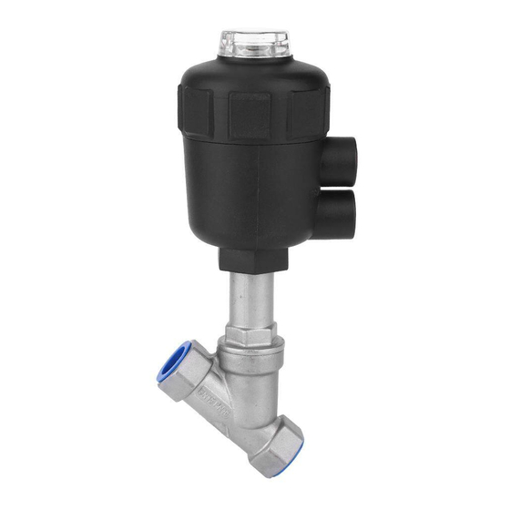
Piston actuated angle seat valve
Hide thumbs
Also See for 2702:
- Operating instructions manual (40 pages) ,
- Operating instructions manual (28 pages) ,
- Operating instructions manual (12 pages)
Chapters
Table of Contents

Subscribe to Our Youtube Channel
Related Manuals for Burkert 2702


Summary of Contents for Burkert 2702
- Page 1 Type 2702 Piston actuated angle seat valve Kolbengesteuertes Schrägsitzventil Soupape de réglage à tête inclinée commandée par piston Operating Instructions Bedienungsanleitung Manuel d‘utilisation...
- Page 2 We reserve the right to make technical changes without notice. Technische Änderungen vorbehalten. Sous réserve de modification techniques. © Bürkert Werke GmbH, 2005 - 2013 Operating Instructions 1308/06_EU-ML_00804367 / Original DE...
-
Page 3: Table Of Contents
Marking of the multipole plugs or sockets and the contacts ..............18 Output signals for SPS (circular plug M 16) ....................19 Operating voltage (circular plug M 12) ......................19 Inductive proximity switches (circular socket M8) ..................19 Process value (circular plug M 8) ........................20 2702 - 3... - Page 4 Replacement of the control plug ........................27 Mounting the actuator............................27 Replacement of the control plug wtih SideControl Typ 1067 ................28 Demounting the actuator ..........................28 Replacement of the control plug ........................29 Mounting the actuator............................30 Spare parts sets type 2702 ............................31 4 - 2702...
- Page 5 General Notes SymbolS..................................6 Intended.uSe................................6 General.Safety.noteS............................. 6 ContaCt.addreSSeS............................7 Warranty..................................7 tranSport,.StoraGe............................7 dISpoSal..................................8 InformatIon.In.Internet..........................8 2702 - 5...
-
Page 6: Generales Notes
Switch off the supply voltage in all cases before intervening in the system! • Note that in systems under pressure, piping and valves may not be loosened! WarnInG! • Observe the current regulations on accident prevention and safety during operation and maintenance of the device! 6 - 2702... -
Page 7: Contact Addresses
The warranty extends only to defects in the delivered Type 2702 valve with pneumatic drive and the TopControl or SideControl. We accept no liability for any kind of collateral damage which can occur due to failure or malfunction of the device. -
Page 8: Disposal
CautIon! environmental.danger! When disponsing of the appliance, observe the national standards for refuse disposal. InformatIon.In.Internet All Operating manuals and Datasheets for the Type 2702 you can find under: www.burkert.com - Technical data www.burkert.com → Documentation 8 - 2702... -
Page 9: Technical Data
Technical data ConstruCtion of the Control valve .................... 10 Media ..................................... 10 Kv value ..................................11 2702 - 9... -
Page 10: Construction Of The Control Valve
0 - 16 bar Actuator size F DN 25 0 - 16 bar Actuator size F DN 32 0 - 15 bar Actuator size G DN 40 0 - 12,5 bar Actuator size G DN 50 0 - 7,2 bar 10 - 2702... - Page 11 ECHNICAL KV VALUE Type 2702 DN 15 Stroke % Stroke [mm] Kv [m 0.23 0.24 0.26 0.35 1.85 10.8 12.0 Stroke % Type 2702 DN 20 Stroke % Stroke [mm] Kv [m 0.30 0.33 0.42 2.85 10.8 12.6 14.4 16.2 18.0...
- Page 12 2702 dn 32 Stroke % Stroke [mm] Kv [m 0.55 0.65 0.95 10.0 12.0 13.8 14.0 16.5 16.0 18.8 18.0 21.0 20.0 23.0 Stroke % type 2702 dn 40 Stroke % Stroke [mm] Kv [m 0.65 0.85 10.4 14.0...
-
Page 13: Commissioning
IndUCtIve PRoxIMItY swItChes (oPtIon foR toPCONTROL tYPe 8630) ....................23 Opening the housing of the TOPControl Continuous..................23 Positioning the inductive proximity switches ......................23 eleCtRICal ConneCtIon - teRMInal foR Cable bUshIng (sIdeCONTROL tYPe 1067) ..........................24 Pin assignment ................................24 2702 - 13... -
Page 14: Installation Of The Valve
The valve must be for this in the opened position. note When using in an aggressive environment, you are advised to connect pneumatic hoses to all free control connections and place their other ends in a neutral atmosphere. 14 - 2702... -
Page 15: Procedure For Sidecontrol Type 1067
The piston moves into the upper position and the plug is separated from the valve seat. Turn only the upper switch to the idle position (4b). The piston stays in the upper position even after the compressed air is switched off. 2702 - 15... - Page 16 The piston actuator is bled and the spring closes the valve. note This procedure causes air to be trapped under the spring-loaded piston. Normally the air will escape slowly. After 10 hours, however, this procedure should be completed. 16 - 2702...
-
Page 17: Pneumatic Installation For Topcontrol Type 8630
Keep variations in the supply pressure as low as possible during operation (max. ± 10%). With larger variations, the controller parameters calibrated with the AUTOTUNE function will not be optimal. 2702 - 17... -
Page 18: Electrical Connection - Multipole Connectors (Topcontrol Type 8630)
The markings of the multipole plugs and sockets, and the contacts are to be found in the respective chapters. Marking of the multipole plugs or sockets and the contacts Output signals Operating voltage to SPS Process value Initiators (inductive proximity switches) 18 - 2702... -
Page 19: Output Signals For Sps (Circular Plug M 16)
Inductive proximity switches (circular socket M8) allocation signal level Proximity switch 1 +(NO) +24 V DC open / 24 V Proximity switch 1 GND Proximity switch 2 +(NO) +24 V DC open / 24 V Proximity switch 2 GND 2702 - 19... -
Page 20: Process Value (Circular Plug M 8)
2 (compensation) * May be set via software (section Procedure for specifying the basic settings) ** The jumper is situated on the connection board of the TOPControl Continuous (see next page) note For line compensation reasons, connect sensor Pt-100 via 3 conductors. PIN 3 and PIN 4 must be bridged at the sensor. 20 - 2702... -
Page 21: Electrical Connection - Terminals For Cable Bushing (Topcontrol Type 8630)
Analog position feedback + + (0/4 ... 20 mA or 0 ... 5/10 V) completely isolated electrically Analog position feedback GND Operating voltage + 24 V DC ± 10 % Operating voltage GND max. residual ripple 10 % 2702 - 21... -
Page 22: Choice Of Binary Outputs Or Process Value Input
Be sure to bridge terminals 9 and 10 at the sensor. terminal allocation with binary outputs terminal allocation external connection Binary input + 0 ... 5 V (log. 0) 10 ... 30 v (log. 1) Binary input GND 22 - 2702... -
Page 23: Setting The Inductive Proximity Switches (Option For Topcontroltyp 8630)
On adjusting the height of the inductive proximity switches, make sure that adjacent flexes are not pulled (e.g. by getting hooked in the proximity switches). Screw to adjust the lower proximity switch Screw to adjust the upper proximity switch 2702 - 23... -
Page 24: Electrical Connection - Terminal For Cable Bushing (Sidecontrol Type 1067)
> 175 W Input (Unit signal 4 ... 20 mA) Input impedance attentIon! To ensure electromagnetic compatibility (EMC resistance), the interior M4 threading of the armature must be connected to ground with the shortest possible cable. M4-internal thread 24 - 2702... -
Page 25: Maintenance And Servicing Of The Valve
Faults................................... 26 Replacement.oF.the.plug.with.topControl.type.8630........... 26 Demounting the actuator .............................26 Replacement of the plug .............................27 Mounting the actuator ..............................27 Replacement.oF.the.plug.with.sideControl.type.1067..........28 Demounting the actuator .............................28 Replacement of the plug .............................29 Mounting the actuator ..............................30 spaRe.paRts.sets.type.2702........................31 2702 - 25... -
Page 26: Faults
(6 bar), so that the plug is lifted from the valve seat and is not damaged. . control.function.B: → With control function B, no compressed air must be applied for this purpose. → Remove the actuator in the open valve position by unscrewing the nipple from the valve body. 26 - 2702... -
Page 27: Replacement Of The Control Plug
→ Before reinstalling the actuator, grease the nipple thread with stainless steel lubricant, e.g.Klüberpaste UH1 96-402 from company Klüber and replace the graphite seal.* → After tightening the threaded nipple, orient the control connection by turning the actuator.* attention! * The valve must be for this in the opened position. 2702 - 27... -
Page 28: Replacement Of The Control Plug Wtih Sidecontrol Typ 1067
The piston moves into the upper position and the plug is separated from the valve seat. Turn only the upper switch to the idle position (4b). The piston stays in the upper position even after the compressed air is switched off. 28 - 2702... -
Page 29: Replacement Of The Control Plug
To pull off the plug, apply compressed air (approx. 6 bar) to the lower pilot air port of the actuator. → Push the new plug over the end of the spindle. → Align the bores. Plug Dowel pin 2702 - 29... -
Page 30: Mounting The Actuator
The piston actuator is bled and the spring closes the valve. note This procedure causes air to be trapped under the spring-loaded piston. Normally the air will escape slowly. After 10 hours, however, this procedure should be completed. 30 - 2702... -
Page 31: Spare Parts Sets Type 2702
AINTENANCE AND ERVICING OF THE VALVE SPARE PART SETS FOR TYPE 2702 STANDARD VERSION Angle seat control valve Plug set WARNING! Danger due to spraying of fluids under high pressure! Always interrupt the medium flow before disassembling or opening the device, and let off the pressure in the hose system. - Page 32 Spare parts sets for special versions are available on request (e.g. oxygen or analysis versions, etc.). 32 - 2702...
- Page 33 Inhaltsverzeichnis Typ 2702 Allgemeine Hinweise ............................35 Darstellungsmittel .................................36 Bestimmungsgemäßer Gebrauch ..........................36 Allgemeine Sicherheitshinweise ..........................36 Kontaktadressen ................................37 Gewährleistung ................................37 Transport und Lagerung ..............................37 Entsorgung ..................................38 Informationen im Internet .............................38 TecHniscHe DATen ............................39 Aufbau des Regelventils ..............................40 Medien .....................................40 Kv-Werte ..................................41...
- Page 34 Demontage des Antriebs ..........................56 Austausch des Regelkegels ..........................57 Montage des Antriebs ............................57 Austausch des Regelkegels bei SideControl Typ 1067 ..................58 Demontage des Antriebs ..........................58 Austausch des Regelkegels ..........................59 Montage des Antriebs ............................60 Ersatzteilsätze für Standardgeräte Typ 2702 ......................61 34 - 2702...
-
Page 35: Allgemeine Hinweise
Allgemeine Hinweise Darstellungsmittel............................36 Bestimmungsgemässer.geBrauch....................36 allgemeine.sicherheitshinweise......................36 KontaKtaDressen.............................. 37 gewährleistung..............................37 transport.unD.lagerung.......................... 37 entsorgung................................38 informationen.im.internet........................38 2702 - 35... -
Page 36: Darstellungsmittel
Schalten Sie vor Eingriffen in das System in jedem Fall die Spannung ab! • Beachten Sie, dass in Systemen, die unter Druck stehen, Leitungen und Ventile nicht gelöst werden dürfen! warnung! • Beachten Sie die geltenden Unfallverhütungs- und Sicherheitsbestimmungen während des Betriebs, der Wartung und der Reparatur des Gerätes! 36 - 2702... -
Page 37: Kontaktadressen
Die Gewährleistung erstreckt sich nur auf die Fehlerfreiheit des gelieferten Ventils Typ 2702 mit pneumatischem Antrieb und des TopControl oder SideControl. Für Folgeschä- den jeglicher Art, die durch Ausfall oder Fehlfunktion des Gerätes entstehen könnten, wird keine Haftung übernommen. -
Page 38: Entsorgung
Vorsicht! gefahr.für.die.umwelt! Beachten Sie bei der Entsorgung des Gerätes die nationalen Abfallbeseitigungsvorschrif- ten. informationen.im.internet Bedienungsanleitungen und Datenblätter zum Typ 2702 finden Sie im Internet unter: www.buerkert.com → Dokumentation 38 - 2702... -
Page 39: Technische Daten
Technische Daten AufbAu des Regelventils .......................... 40 Medien ..................................40 Kv-WeRte .................................. 41 2702 - 39... -
Page 40: Aufbau Des Regelventils
DN 20 0 - 16 bar Antriebsgröße F DN 25 0 - 16 bar Antriebsgröße F DN 32 0 - 15 bar Antriebsgröße G DN 40 0 - 12,5 bar Antriebsgröße G DN 50 0 - 7,2 bar 40 - 2702... -
Page 41: Kv-Werte
ECHNISCHE ATEN KV-WERTE Typ 2702 DN 15 Hub % Hub [mm] Kv [m 0,23 0,24 0,26 0,35 1,85 10,8 12,0 Hub % Typ 2702 DN 20 Hub % Hub [mm] Kv [m 0,30 0,33 0,42 2,85 10,8 12,6 14,4 16,2... - Page 42 2702 dn 32 Hub % Hub [mm] Kv [m 0,55 0,65 0,95 10,0 12,0 13,8 14,0 16,5 16,0 18,8 18,0 21,0 20,0 23,0 Hub % typ 2702 dn 40 Hub % Hub [mm] Kv [m 0,65 0,85...
-
Page 43: Inbetriebnahme
Auswahl zwischen binären Ausgängen und Prozess-Istwert-Eingang ............52 EinstEllEn dEr induktiVEn nähErungsschaltEr (oPtion bEi toPControltyP 8630) ....................... 53 Öffnen des TOP Control Continuous-Gehäuses ....................53 Positionieren der induktiven Näherungsschalter....................53 ElEktrischEr anschluss - klEmmEn für kabElVErschraubung (sidEControl tyP 1067) ..........................54 Anschlussbelegung ..............................54 2702 - 43... -
Page 44: Einbau Des Ventils
7. Richten Sie nach Festziehen des Gewindenippels die Steueranschlüs- se durch Verdrehen des Antriebes aus. achtung! Das Ventil muss sich in der geöffneten Stellung befinden. hinWEis Bei Einsatz in aggressiver Umgebung empfehlen wir, sämtliche freien Pneumatikanschlüsse mit Hilfe eines Pneumatikschlauches in neutrale Atmosphäre abzuleiten. 44 - 2702... -
Page 45: Vorgehensweise Bei Sidecontrol Typ 1067
Der Kolben bewegt sich daraufhin in die obere Lage und der Regelkegel wird vom Ventilsitz getrennt. Drehen Sie nur den oberen Schalter bis zur Ru- helage (4b). Der Kolben bleibt in der oberen Lage, auch wenn die Druckluft abgeschaltet wird. 2702 - 45... - Page 46 Drehen Sie den unteren Schalter in die Ruhelage zurück. Der Kolbenantrieb wird entlüftet und die Feder schliesst das Ventil. hinWEis Durch diese Vorgehensweise wird Luft unter dem federbelasteten Kolben eingeschlossen. Normalerweise entweicht die Luft langsam. Nach 10 Stunden sollte dieser Vorgang jedoch abgeschlossen sein. 46 - 2702...
-
Page 47: Pneumatische Installation Bei Topcontrol Typ 8630
Regelverhalten im oberen Hubbereich aufgrund zu kleiner Druckdifferenz nicht stark negativ beeinflusst wird. Halten Sie die Schwankungen des Versorgungsdrucks während des Betriebs möglichst ge- ring (max. ±10 %). Bei größeren Schwankungen sind die mit der Funktion Autotune einge- messenen Reglerparameter nicht optimal. 2702 - 47... -
Page 48: Elektrischer Anschluss - Multipolstecker (Topcontrol Typ 8630)
Bei Profibus DP oder DeviceNet: Die Bezeichnung der Multipolstecker bzw. -buchsen und der Kontakte finden Sie in den jewei- ligen Kapiteln. bezeichnung der multipolstecker bzw. -buchsen und der kontakte Ausgangssignale Betriebsspannung zur SPS Prozess-Istwert Initiatoren (Induktive Näherungsschalter) 48 - 2702... -
Page 49: Ausgangssignale Zur Sps ( Rundstecker M 16)
Restwelligkeit 10 % nicht belegt induktive näherungsschalter (buchse rund m 8) belegung signalpegel Näherungsschalter 1 +(NO) +24 V DC offen / 24 V Näherungsschalter 1 GND Näherungsschalter 2 +(NO) +24 V DC offen / 24 V Näherungsschalter 2 GND 2702 - 49... -
Page 50: Prozess-Istwert (Rundstecker M 8)
* über software einstellbar (siehe kapitel Vorgehensweise zum Festlegen der Grundeinstellungen) ** der Jumper befindet sich auf der anschlussplatine des toPControl continuous (s. nächste seite) hinWEis Sensor Pt-100 aus Leitungskompensationsgründen über 3 Leitungen anschließen. PIN 3 und PIN 4 unbedingt am Sensor brücken. 50 - 2702... -
Page 51: Elektrischer Anschluss - Klemmen Für Kabelverschraubung (Topcontrol Typ 8630)
+ (0/4 ... 20 mA oder 0 ... 5/10 V) Sollwert GND Analoge Stellungsrückmeldung + + (0/4 ... 20 mA oder 0 ... 5/10 V) komplett galvanisch getrennt Analoge Stellungsrückmeldung GND Betriebsspannung + 24 V DC ± 10 % Betriebsspannung GND max. Restwelligkeit 10 % 2702 - 51... -
Page 52: Auswahl Zwischen Binären Ausgängen Und Prozess-Istwert-Eingang
Sensor Pt-100 aus Leitungskompensationsgründen über 3 Leitungen anschließen. Klemme 9 und Klemme 10 unbedingt am Sensor brücken. klemmenbelegung der binären Eingänge klemme belegung äußere beschaltung Binärer Eingang + 0 ... 5 V (log. 0) 10 ... 30 V (log. 1) Binärer Eingang GND 52 - 2702... -
Page 53: Einstellen Der Induktiven Näherungsschalter (Option Bei Topcontroltyp 8630)
Achten Sie beim Höhenverstellen der Näherungsschalter darauf, dass benachbarte Litzen nicht zugbelastet werden (z. B. durch Einhaken an den Näherungsschaltern). Schraube zum Verstellen des unteren Näherungsschalters Schraube zum Verstellen des oberen Näherungsschalters 2702 - 53... -
Page 54: Elektrischer Anschluss - Klemmen Für Kabelverschraubung (Sidecontrol Typ 1067)
0/4 ... 20 mA) Eingangswiderstand > 175 W Eingang (Einheitssignal 4 ... 20 mA) Eingangswiderstand achtung! Zur Gewährleistung der elektromagnetischen Verträglichkeit (EMV) muss das M4- Innen- gewinde der Armatur mit einem möglichst kurzen Kabel an die Erde gelegt werden. M4-Innengewinde 54 - 2702... -
Page 55: Instandhaltung Und Wartung Des Ventils
Instandhaltung und Wartung des Ventils Störungen................................56 AuStAuSch.deS.regelkegelS.bei.topControl.typ.8630..........56 Demontage des Antriebs ............................56 Austausch des Regelkegels ............................57 Montage des Antriebs..............................57 AuStAuSch.deS.regelkegelS.bei.SideControl.typ.1067..........58 Demontage des Antriebs ............................58 Austausch des Regelkegels ............................59 Montage des Antriebs..............................60 erSAtzteilSätze.für.StAndArdgeräte.typ.2702..............61 2702 - 55... -
Page 56: Störungen
(6 bar), damit der Regelkegel vom Ventilsitz abhebt und nicht beschä- digt wird. . Steuerfunktion.b: → Bei Steuerfunktion B muss hierzu keine Druckluft angelegt werden. → Entfernen Sie den Antrieb in offener Ventilstellung durch Losschrauben des Nippels vom Gehäuse. 56 - 2702... -
Page 57: Austausch Des Regelkegels
→ Fetten Sie vor Wiedereinbau des Antriebes das Nippelgewinde mit Edelstahlschmierstoff ein, z.B. Klüber- paste UH1 96-402 der Firma Klüber, und erneuern Sie die Graphitdichtung.* → Richten Sie nach Festziehen des Gewindenippels die Steueranschlüsse durch Verdrehen des Antriebes aus.* Achtung! * Das Ventil muss sich in der geöffneten Stellung befinden. 2702 - 57... -
Page 58: Austausch Des Regelkegels Bei Sidecontrol Typ 1067
Der Kolben bewegt sich daraufhin in die obere Lage und der Regelkegel wird vom Ventilsitz getrennt. Drehen Sie nur den oberen Schalter bis zur Ruhela- ge (4b). Der Kolben bleibt in der oberen Lage, auch wenn die Druckluft abgeschaltet wird. 58 - 2702... -
Page 59: Austausch Des Regelkegels
Antriebes geklemmt werden. Geben Sie zum Abziehen des Regelkegels auf den unteren Steueranschluss des Antriebes Druckluft (6 bar). → Stecken Sie den neuen Regelkegel auf das Spindelende. Regelkegel → Richten Sie die Bohrungen zueinander aus. Spannstift 2702 - 59... -
Page 60: Montage Des Antriebs
Drehen Sie den unteren Schalter in die Ruhelage zurück. Der Kolbenantrieb wird entlüftet und die Feder schliesst das Ventil. hinWeiS Durch diese Vorgehensweise wird Luft unter dem federbelasteten Kolben eingeschlossen. Normalerweise entweicht die Luft langsam. Nach 10 Stunden sollte dieser Vorgang jedoch abgeschlossen sein. 60 - 2702... -
Page 61: Ersatzteilsätze Für Standardgeräte Typ 2702
NSTANDHALTUNG UND ARTUNG DES ENTILS ERSATZTEILSÄTZE FÜR STANDARDGERÄTE TYP 2702 Schrägsitzregelventil Regelkegelsatz WARNUNG! Gefahr durch Herausspritzen von Flüssigkeiten unter hohem Druck! Unterbrechen Sie vor dem Ausbau oder dem Öffnen des Gerätes immer die Mediumszu- fuhr und bauen Sie den Druck im Leitungssystem ab. - Page 62 Ersatzteilsätze für Sonderausführungen erhalten Sie auf Anfrage (z. B. Sauerstoff-, Analyseausführungen usw.). 62 - 2702...
- Page 63 Sommaire du type 2702 REMARQUES GENERALES ..........................65 Représentation ................................66 Utilisation conforme à la destination .........................66 Consignes générales de sécurité ..........................66 Adresses ..................................67 Garantie légale ................................67 Transport et stockage ..............................67 Réglementation concernant les déchets .........................68 Information sur Internet ..............................68 CARACTÉRISTIQUES TECHNIQUES......................
- Page 64 Montage de l’entraînement ..........................87 Remplacement du cône de réglage sur SideControl Typ 1067 ...............88 Démontage de l’entraînement .........................88 Changer le pointeau de réglage ........................89 Montage de l’entraînement ..........................90 Jeux de pièces de rechange pour appareils standard Type 2702 ..............91 64 - 2702...
-
Page 65: Remarques Generales
Remarques Generales ............................... 66 RepRésentation ....................66 Utilisation.confoRme.à.la.destination ......................66 consignes.généRales.de.sécURité ..................................67 adResses..............................67 gaRantie.légale ............................ 67 tRanspoRt.et.stockage ..................68 Réglementation.conceRnant.les.déchets infoRmations.sUR.inteRnet........................68 2702 - 65... -
Page 66: Représentation
Tenir compte que dans les systémes sous pression, les conduites et soupapes ne doivent pas être desserrées! aveRtissement! • Respecter les règles de prévention des accidents et de sécurité pendant le fonc- tionnement, la maintenance et les réparations de l’appareil ! 66 - 2702... -
Page 67: Adresses
La condition pour bénéficier de la garantie légale est l’utilisation conforme de l’appareil dans le respect des conditions d’utilisation spécifiées. indication! La garantie ne couvre que l’absence de défaut du robinet à bille synthétique du type 2702 et de ses composants. Nous déclinons toute responsabilité pour les dommages de toute nature qui résultent de la panne ou du dysfonctionnement de l’appareil. -
Page 68: Réglementation Concernant Les Déchets
Réglementation.conceRnant.les.déchets attention! Risques.pour.l’environnement.! Respectez les réglementations nationales en matière d‘élimination des déchets. infoRmations.sUR.inteRnet Vous trouverez des notices et des fiches techniques du type 2702 sur Internet sous : www.buerkert.fr → Fiches techniques 68 - 2702... -
Page 69: Caractéristiques Techniques
Caractéristiques techniques Structure de la Soupape de réglage ..................70 FluideS ..................................40 ValeurS KV ................................41 2702 - 69... -
Page 70: Structure De La Soupape De Réglage
0 - 16 bar Grandeur d’entraînement F DN 25 0 - 16 bar Grandeur d’entraînement F DN 32 0 - 15 bar Grandeur d’entraînement G DN 40 0 - 12,5 bar Grandeur d’entraînement G DN 50 0 - 7,2 bar 70 - 2702... -
Page 71: Valeurs Kv
ARACTÉRISTIQUES ECHNIQUES VALEURS KV Type 2702 DN 15 Course % Course [mm] Kv [m 0,23 0,24 0,26 0,35 1,85 10,8 12,0 Course % Type 2702 DN 20 Course % Course [mm] Kv [m 0,30 0,33 0,42 2,85 10,8 12,6 14,4... - Page 72 2702 dn 32 Course % Course [mm] Kv [m 0,55 0,65 0,95 10,0 12,0 13,8 14,0 16,5 16,0 18,8 18,0 21,0 20,0 23,0 Course % type 2702 dn 40 Course % Course [mm] Kv [m 0,65 0,85...
-
Page 73: Mise En Service
(optIon aVeC topCONTROL tYpe 8630) ....................83 Ouverture du boîtier du TopControl Continuous ....................83 Positionnement des détecteurs de proximité inductifs ..................83 BoRnes de RaCCoRdeMent éleCtRIQue pouR passe-CÂBle à VIs (sIdeCONTROL tYpe 1067) ..........................84 Affectation des raccordements ..........................84 2702 - 73... -
Page 74: Montage De La Soupape
La soupape doit également se trouver à cet effet en position ouverte. IMpoRtant! En cas d‘utilisation dans un environnement afressif, nous recommandons de dévier tous les raccordements pneumatiques libres dans une atmosphère neutre à l‘aide d‘un tuyau flexible pneumatique. 74 - 2702... -
Page 75: Mode Opératoire Avec Sidecontrol Type 1067
Le piston se déplace alors en position supérieure et le cône de réglage est séparé du siège de la sou- pape. Tourner uniquement le commutateur supérieur jusqu’en position de repos (4b). Le piston demeure en position supérieure même quand l’air comprimé est coupé. 2702 - 75... - Page 76 L’entraînement du piston est purgé et le ressort fer- me la soupape. IMpoRtant! Ce mode opératoire inclut de l’air sous le piston à charge de ressort. L’air s’échappe en prin- cipe lentement. Mais ce processus devrait cependant être achevé après 10 heures. 76 - 2702...
-
Page 77: Installation Pneumatique Avec Topcontrol Type 8630
Maintenir les variations de la pression d’alimentation pendant le service dans des limites aussi faibles que possible (max. ± 10 %). En cas de variations plus fortes, les paramètres du régulateur étalonnés avec la fonction AUTOTUNE ne sont pas optimaux. 2702 - 77... -
Page 78: Raccordement Èlectrique - Connecteurs Multpôles (Topcontrol Type 8630)
La désignation des connecteurs resp. douilles multibroches et des contacts se trouve dans les chapitres respectifs. désignation des connecteurs multipôles resp. des douilles et des contacts Signaux de sortie Tension de service vers SPS Valeur réelle Détecteurs de proximité inductifs processus 78 - 2702... -
Page 79: Signaux De Sortie Vers Sps (Connecteur Coaxial M16)
Détecteur de proximité 1 +(NO) +24 V DC ouvert / 24 V Détecteur de proximité 1 GND Détecteur de proximité 2 +(NO) +24 V DC ouvert / 24 V Détecteur de proximité 2 GND 2702 - 79... -
Page 80: Valeur Réelle De Processus (Connecteur Coaxial M 8)
** Le cavalier se trouve sur la platine de raccordement du TOP Control Continuous (v. page suivante) IMpoRtant! Pour des raisons de compensation des conducteurs, branchez le capteur PT 100 au moyen de 3 conducteurs. Il faut impérativement ponter les broches 3 et 4 au capteur 80 - 2702... -
Page 81: Bornes De Raccordement Électrique Pour Passe-Câble À Vis (Topcontrol Type 8630)
+ (0/4 ... 20 mA ou 0 ... 5/10 V) entièrement séparé galvaniquement Quittance de position analogique GND Tension de service + 24 V DC ± 10 % Tension de service GND ondulation résiduelle max. 10 % 2702 - 81... -
Page 82: Choix Entre Sorties Binaires Et Entrée De Valeur Réelle De Processus
Raccorder le capteur Pt-100 par 3 lignes pour des raisons de compensation de ligne. Ponter impérativement les bornes 9 et 10 sur le capteur. Raccords entrée binaire Borne occupation Montage extérieur Entrée binaire + 0 ... 5 V (log. 0) 10 ... 30 V (log. 1) Entrée binaire GND 82 - 2702... -
Page 83: Réglage Des Détecteurs De Proximité Inductifs (Option Avec Topcontroltype 8630)
Veiller en réglant les détecteurs de proximité en hauteur à ce que des torons voisins nesoi- ent pas soumis à une traction (p.ex. en les accrochant aux détecteurs). Vis pour régler le détecteur inférieur Vis pour régler le détecteur supérieur 2702 - 83... -
Page 84: Bornes De Raccordement Électrique Pour Passe-Câble À Vis (Sidecontrol Typ 1067)
Entrée (signal d’unité 4 ... 20 mA) Résistance d’entrée IndICatIon! Le taraudage M4 de l’armature doit être mis à la terre avec un câble aussi court que possible afin de garantir la compatibilité électromagnétique (CEM). Taraudage M4 84 - 2702... -
Page 85: Entretien Et Maintenance De La Vanne
Entretien et maintenance de la soupape Pannes..................................86 ReMPLaCeMenT.DU.COne.De.ReGLaGe.sUR.TOPCONTROL.TYPe.8630......86 Démontage de l’entraînement ............................86 Changer le pointeau de réglage ..........................87 Montage de l’entraînement ............................87 ReMPLaCeMenT.DU.COne.De.ReGLaGe.sUR.CONTROL.TYP.1067........88 Démontage de l’entraînement ............................88 Changer le pointeau de réglage ..........................89 Montage de l’entraînement ............................90 JeUx.De.PièCes.De.ReChanGe.POUR.aPPaReiLs.sTanDaRD.TYPe.2702...... 91 2702 - 85... -
Page 86: Pannes
. Fonction.de.commande.B: → Pas de chargement d‘air comprimé pour la fonction B. → Enlever le mécanisme en position ouverte de la soupape, en dévisant le raccorddu boîtier. 86 - 2702... -
Page 87: Changer Le Pointeau De Réglage
Klüber UH1 96-402 de la maison Klüber, et renouveler le joint graphite.* → Après avoir serré le raccord fileté, ajuster les raccords de commande par rotation de l’entraînement.* inDiCaTiOn! * La soupape doit également se trouver à cet effet en position ouverte. 2702 - 87... -
Page 88: Remplacement Du Cône De Réglage Sur Sidecontrol Typ 1067
Le piston se déplace alors en position supérieure et le cône de réglage est séparé du siège de la soupape. Tourner uniquement le commutateur supérieur jusqu’en position de repos (4b). Le piston demeure en position supérieure même quand l’air comprimé est coupé. 88 - 2702... -
Page 89: Changer Le Pointeau De Réglage
(env. 6 bars) sur le raccordement inférieur de la commande du mécanisme. → Mettre le nouveau pointeau en place au bout de la broche. Pointeau de → Aligner les alésages les uns par rapport aux autres. Goupille réglage 2702 - 89... -
Page 90: Montage De L'entraînement
L’entraînement du piston est purgé et le ressort ferme la soupape. iMPORTanT! Ce mode opératoire inclut de l’air sous le piston à charge de ressort. L’air s’échappe en prin- cipe lentement. Mais ce processus devrait cependant être achevé après 10 heures. 90 - 2702... -
Page 91: Jeux De Pièces De Rechange Pour Appareils Standard Type 2702
EMISE EN TAT ET NTRETIEN JEUX DE PIÈCES DE RECHANGE POUR APPAREILS STANDARD TYPE 2702 Soupape de réglage à siège incliné Jeu de cônes de réglage AVERTISSEMENT! Danger dû à des liquides qui giclent sous haute pression ! Interrompre toujours l’alimentation de fluide avant de démonter ou d’ouvrir l’appareil et détendre la pression dans le systèmes de conduites. - Page 92 Vous recevrez sur demande les jeux de pièces de rechange pour les versions spéciales iMPORTanT! (p.ex. versions pour analyse, oxygène etc.) 92 - 2702...
- Page 94 www.burkert.com...
Need help?
Do you have a question about the 2702 and is the answer not in the manual?
Questions and answers