
Subscribe to Our Youtube Channel
Related Manuals for Thor Broadcast Thor Fiber HD-IRD-V3-ATSC-DVBS2


Summary of Contents for Thor Broadcast Thor Fiber HD-IRD-V3-ATSC-DVBS2
- Page 1 User Manual HD-IRD-V3-ATSC-DVBS2 Universal Satellite and ATSC IRD Revision 5.22.2018 Thor Fiber 2018 Tel: (800) 521-8467 Email: sales@thorfiber.com http://www.thorbroadcast.com...
-
Page 2: Table Of Contents
Table of Contents A NOTE FROM THOR BROADCAST ABOUT THIS MANUAL ............3 ..........................3 NTENDED UDIENCE ............................3 ISCLAIMER ............................ 3 ARNING CHAPTER 1 PRODUCT OUTLINE ...................... 4 1.1 O ............................4 VERVIEW 1.2 F ............................4 EATURES 1.3 S .......................... -
Page 3: A Note From Thor Broadcast About This Manual
A Note from Thor Broadcast about this Manual Intended Audience This user manual has been written to help people who have to use, integrate and to install the product. Some chapters require some prerequisite knowledge in electronics and especially in broadcast technologies and standards. -
Page 4: Chapter 1 Product Outline
Chapter 1 Product Outline 1.1 Overview Universal Satellite and ATSC IRD is our all-in-one device which integrates demodulation, de-scrambler, re-mux and decoding in one case to convert RF signals into audio/video (CVBS/YPbPr/HDMI/SDI) output. It is a 1-U case which supports 2 tuner inputs to receive signal from satellite. The two CAMs/CIs accompanied can descramble the programs input from encrypted RF, ASI and IP. -
Page 5: Specifications
1.3 Specifications Input 2 x DVB-S/S2RF, F type 1×ASI input for re-mux, BNC interface 1xIP input for re-mux (UDP) Demodulating Section ATSC Input Frequency 54MHz~858MHz Bandwidth 6M bandwidth DVB-S2 (Version 1) Input Frequency 950-2150MHz Symbol rate QPSK 1~45Mbauds; 8PSK 2~30Mbauds Code rate 1/2, 3/5, 2/3, 3/4, 4/5, 5/6, 8/9, 9/10 Constellation... -
Page 6: Principle Chart
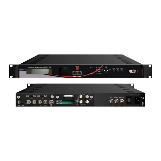
System Local interface LCD + control buttons Remote Web-server Management management Language English Upgrade USB, web management General Power supply AC 100V~240V Dimensions 482*300*44.5mm Weight 3 kgs 0~45℃ Operation temperature 1.4 Principle Chart 1.5 Appearance and Description Monitor LCD display for device control and configuration Mini LCD TV for decoding Mini LCD TV power switch NMS Port (for PC connection) -
Page 7: System Connection Sample
status; Lock 3:to indicate the IP or ASI signal Lock status; Decoder: to indicate the decoding status) Up/Down/Left/Right Buttons Enter Key Menu Key Lock Key Rear Panel Illustration USB upgrade port HDMI video/audio output Component video output (YPbPr) Decoder Composite video output (CVBS) Board SDI video/audio output Analog stereo audio out 1 (R/L) -
Page 8: Chapter 2 Installation Guide
Chapter 2 Installation Guide 2.1 Acquisition Check When user opens the package of the device, it is necessary to check items according to packing list. Normally it should include the following items: Universal Satellite and ATSC IRD User’s Manual ... -
Page 9: Environment Requirement
2.2.2 Environment Requirement Item Requirement When user installs machine frame array in one machine hall, the distance between 2 rows of machine frames Machine Hall Space should be 1.2~1.5m and the distance against wall should be no less than 0.8m. Electric Isolation, Dust Free Volume resistivity of ground anti-static material: Machine Hall Floor... -
Page 10: Frame Grounding
• It is prohibited to use any other device as part of grounding electric circuit • The area of the conduction between grounding wire and device’s frame should be no less than 25mm 2.2.4 Frame Grounding All the machine frames should be connected with protective copper strip. The grounding wire should be as short as possible and avoid circling. -
Page 11: Universal Satellite And Atsc Ird Cables Illustration
2.4.1 Universal Satellite and ATSC IRD Cables Illustration: • IP Input/output Cable Illustration: • Tuner Cable Illustration: • ASI Input/output Cable Illustration: • Video & Audio output Cable Illustration: (for connection between the IRD and TV set or home theater) CVBS Cable YPbPr Cable Thor Fiber 2018... - Page 12 HDMI Cable SDI Cable • Audio adapt cables Illustration: (for connection between the IRD and TV set) Thor Fiber 2018 Tel: (800) 521-8467 Email: sales@thorfiber.com http://www.thorbroadcast.com...
-
Page 13: Chapter 3 Operation
Chapter 3 Operation The front panel of Universal Satellite and ATSC IRD is the user-operating interface and the equipment can be conveniently operated and managed according to the procedures displayed on the LCD: Keyboard Function Description: MENU: Cancel current entered value, resume previous setting; Return to previous menu. ENTER: Activate the parameters which need modifications, or confirm the change after modification. - Page 14 Input Sets 3 ASI: 3: ASI TS Lock Parse Program Select Program Input Sets 4: IP IP Config: 4: IP IP Config Input IP Input Port Multicast IGMP Snooping Service IP IP Bypass 4: IP Mux Program: TS Lock Mux Program Parse Program Select Program Card A:...
- Page 15 Main Menu: IP Stream: IP Stream Service IP IP Stream: Subnet Mask IP Stream: Gateway IP Stream: Output Protocol MPTS 1: IP Stream: Data Enable MPTS 1 Null PKT Filter Output IP Output Port SPTS 1: IP Stream: Data Enable SPTS 1 Null PKT Filter Output IP...
-
Page 16: General Setting
3.2 General Setting Switch on the device and after a few seconds of initialization, it will show start-up pictures as below: HD IRD Start up… Start OK… Bitrate: xx.xxx Mbps HD IRD: Device’s name Bitrate: xx.xxx MHz indicates the current effective bitrate multiplexed output. Press LOCK key on the front panel to enter the main menu. -
Page 17: Input Sets
3.2.2 Input Sets This IRD supports 2 tuners input, 1 ASI input and 1 IP stream input. Users can enter ‘Input Sets’ to configure the tuner/IP parameters to receive the transport streams and select programs to mux out. It displays as below: Input Sets 1 Tuner DVBS/S2 2 Tuner DVBS/S2... - Page 18 For reading the input TS Locked Mux Program bitrate Bitrate: 4.040 Mbps TS Lock Parse Program For reading the number Searching Program Select Program of programs from Tuner Get 7 Programs 1 (or 2) Process of selecting programs to Mux Program (0/7) output through front panel: 1: CCTV 1 [←]: to cancel program output;...
- Page 19 Mux Program: Users can parse the DVB-S2 Tuner input program list and select program(s) to mux out in this menu. The operating method is same with ATSC Tuner. ASI: Users can parse ASI input programs and select program(s) to mux out under this menu. The operating method is same with what explained above.
-
Page 20: Ci Card
3.2.3 CI Card This IRD supports 2 CI cards (Card A & Card B) to descramble programs from either encrypted RF, ASI or IP. Users can press ENTER key to enter ‘CI Card’ to configure the 2 cards respectively. CI Card Card A Card B Press ENTER key to enter Card A (or Card B):... - Page 21 Card Error Check Enable ► CI Card Delay Users can set the CI Card delay in this menu. CI Card Delay Parse Program Users can read the quantity of programs parsed from the de-scrambled channel. Searching Program Get 8 Programs ...
-
Page 22: Biss Descrambling
3.2.4 BISS Descrambling NDS356X IRD also supports BISS to descramble encrypted programs from RF, ASI or IP. Users can enter 2 BISS descrambling to configure the 2 BISS respectively. CI Card BISS A BISS B Press ENTER key to enter BISS A (or BISS B): BISS A Input TS Mode Burned Key... -
Page 23: Ts Config
Burned Key/Descrambler Key/SK/Word Mode Users need to input keys to descramble programs as per the BISS scrambling side which usually is DVB-S/S2 modulator. The descrambling format is in the following chart: Modulating Side (BISS SCR) Receiving Side (BISS DESCR) Digit (0x----) Mode 1+SW Data Mode 1+Descrambler Key... - Page 24 TS output mode: Enter this menu to select a TS output mode. Under this mode, users can randomly select TS output mode programs from any input channel to mux out. To passthrough programs from RF 1/2 Tuner 1 Tuner 2 To passthrough programs from ASI IN To passthrough programs from IP IN TS Out Bit rate: Users can set TS output bit rate in this menu.
-
Page 25: Decoder
3.2.6 Decoder Users can press ENTER key to enter ‘Decoder’ to set the video to be decoded. This IRD supports one channel program to output at various interfaces at the same time (HDMI/SDI/CVBS/YPbPr). Decoder To set video/audio ►Video Format parameters for the Audio 1 Mode output program Audio 1 Select... -
Page 26: Ip Stream
3.2.7 IP Stream This IRD supports 1MPTS and 8 SPTS over IP (UDP, RTP/RTSP) output. Users can set the IP out parameters in this menu. IP Stream Service IP To configure the general Subnet Mask parameters for the IP out Gateway Output Protocol MPTS 1... -
Page 27: System
3.2.9 System Users can set the system parameters in this menu. Enter ‘System’ submenu to separately set corresponding parameters. System Save Config Load Saved CFG Factory Reset LCD Time-out Key Password Lock Keyboard Product ID Version Choose yes to save settings. Save Configuration? Press ENTER to confirm Load Saved CFG? -
Page 28: Chapter 4 Web-Based Nms Management
Chapter 4 Web-based NMS Management User not only can use front buttons for setting configuration, but also can control and set the configuration in computer by connecting the device to web NMS Port. User should ensure that the computer’s IP address is different from this device IP address; otherwise, it would cause IP conflict. 4.1 Login The default IP address of this device is 192.168.0.136. - Page 29 System information Input information of the two satellite signals, ASI and IP stream. Output information of the TS and decoded program. User can click any item here to enter the corresponding interface check Figure-2 information or set the parameters. Parameters → Input 1 (Tuner 1:ATSC): From the menu on left side of the webpage, clicking “Input 1 ATSC”, displays the interface where users can configure the first RF input parameters.
- Page 30 Figure-3 Parameters → Input 2 (Tuner 1:DVB-S2): From the menu on left side of the webpage, clicking “Input 2 DVB-S2”, displays the interface where users can configure the first RF input parameters. (Figure-4) Configure parameters in this area according signal RF input source receive...
- Page 31 Figure-5 Parameters → Input 4 (IP Input): On left side of the webpage, clicking “Input 4”, displays the interface where users can configure the IP input parameters. (Figure-6) Configure IP parameters in this area according to IP source receive programs. Click “Apply”...
- Page 32 Card Selection Area Program list from the channel selected in ‘Input TS Mode’ Figure-7 CI Max Bit rate CI Max Bitrate options range from 48-108Mbps. Select a value in the pull-down list as principle: Actual Input Bitrate≤ Max Bitrate≤CI Max decrypting capacity. NOTE! ...
- Page 33 After configuring CI card parameters, click button to apply the input data and then click button to parse programs from the channel selected in ‘Input TS Mode’. Check the program(s) to be descrambled and click button to start descrambling the checked program(s).
- Page 34 Figure-8 Input TS Mode: This IRD has 4 signal sources: Tuner 1-2, ASI, and IP. One BISS tag can be applied to descramble one channel input signal from the 4 signal sources. ‘Skip BISS’ means not to involve BISS function and it is used for FTA stream.
- Page 35 Figure-9 Check the program(s) to be descrambled with “√” and click button to start descrambling the checked program(s). The program quantity to be descrambled will depend on the CAM/CI performance you apply to. Number before slash indicates the programs which have been descrambled. Number behind slash indicates the whole programs from the selected channel.
- Page 36 Figure-10 Output TS Mode: Under this mode, users can randomly select programs from any input channel to mux out. To passthrough programs from Tuner 1/2 To passthrough programs from ASI To passthrough programs from IP ASI Output Select: The TS content output through ASI is copied from the one of the IP streams (MPTS and SPTS 1-8).
- Page 37 Select one input program first and click this button to transfer the selected program to the right box to output. Similarly, user can cancel the multiplexed programs from the right box. To select all the input programs To select all the output programs To parse programs time limitation of parsing input programs ...
- Page 38 Click this button to add new columns. Operation Area Figure-13 After finishing the configuration, click to confirm. Parameters → Decoder: This IRD supports decode program to output at HDMI/SDI/CVBS/YPbPr. Users can configure the Video/Audio output parameters in this tag. (Figure-14) Thor Fiber 2018 Tel: (800) 521-8467 Email: sales@thorfiber.com...
- Page 39 To set the video and audio Primary Audio parameters for the program Secondary Audio to be decoded It displays all the input programs. Select program here to decode and output. Figure-14 NOTE: This IRD supports maximum 2 channels of analog stereo audios output simultaneously. ...
- Page 40 Figure-15 Parameters → Network: From the menu on left side of the webpage, clicking “Network”, it will display the screen as Figure-16 where to configure the network parameters for the device. Thor Fiber 2018 Tel: (800) 521-8467 Email: sales@thorfiber.com http://www.thorbroadcast.com...
- Page 41 Use this IP to connect the device to PC for management. Figure-16 System → LCD/Keyboard: From the menu on left side of the webpage, clicking “LCD/Keyboard”, it will display the screen as Figure-17 where to control the device’s front panel. Figure-17 System →...
- Page 42 Figure-18 System → Save/Restore: From the menu on left side of the webpage, clicking “Save/Restore”, it will display the screen as Figure-19 where to save or restore your configurations. Figure-19 System → Backup/Load: From the menu on left side of the webpage, clicking “Backup/Load”, it will display the screen as Thor Fiber 2018 Tel: (800) 521-8467 Email: sales@thorfiber.com...
- Page 43 Figure-18 where to backup or load your configurations. Figure-20 System → Firmware: From the menu on left side of the webpage, clicking “Firmware”, it will display the screen as Figure-19 where to update firmware for the device. Thor Fiber 2018 Tel: (800) 521-8467 Email: sales@thorfiber.com http://www.thorbroadcast.com...
- Page 44 Figure-21 System → Reboot: From the menu on left side of the webpage, clicking “Reboot”, it will display the screen as Figure-22 where to restart the device manually. Figure-22 Thor Fiber 2018 Tel: (800) 521-8467 Email: sales@thorfiber.com http://www.thorbroadcast.com...
-
Page 45: Chapter 5 Troubleshooting
Chapter 5 Troubleshooting Our ISO9001 quality assurance system has been approved by the CQC organization. To guarantee the products’ quality, reliability and stability. All of our products have been passed the testing and inspection before ship out factory. The testing and inspection scheme already covers all the Optical, Electronic and Mechanical criteria which have been published by us. -
Page 46: Warranty Term
Warranty Term HD-IRD-V3-ATSC-DVBS2 is covered by TWO YEARS LIMITED WARRANTY, which starts from the initial date of your purchase. We provide its customer whole-life technical supports. If warranty is expired, repair service only charges parts (if required). In the event that a unit must be returned for service, before returning the unit, please be advised that: 1.
Need help?
Do you have a question about the Thor Fiber HD-IRD-V3-ATSC-DVBS2 and is the answer not in the manual?
Questions and answers