Table of Contents
Advertisement
Advertisement
Table of Contents

Subscribe to Our Youtube Channel
Related Manuals for LumaSense SmartDGA


Summary of Contents for LumaSense SmartDGA
- Page 1 SmartDGA ®...
- Page 2 LumaSense Technologies prohibits the duplication of any portion of this manual or the use thereof for any purpose other than the operation or maintenance of the equipment described in this manual, without the express written permission of LumaSense Technologies or Advanced Energy Industries, Inc.
-
Page 3: Table Of Contents
1.3 System Requirements ....................7 1.4 Limit of Liability and Warranty ................8 1.5 Malfunction or Service Request ................8 1.6 Shipments to LumaSense for Repair ..............8 1.7 Disposal and Decommissioning ................9 System Overview ......................11 2.1 System Components ....................12 2.1.1... - Page 4 4.3.2 VA-0 Installation ....................42 SmartDGA System Installation ..................49 5.1 SmartDGA Instrument .................... 49 5.1.1 Parts and Tools for the SmartDGA Instrument ............ 49 5.1.2 Mounting the SmartDGA Instrument ..............49 5.2 EZHub ........................50 5.2.1 Parts and Tools for the EZHub ................50 5.2.2...
- Page 5 RS485 Connections .............. 96 9.3 LumaSMART iCore Ethernet Connections ............97 9.4 Unistrut Stand ......................98 9.5 SmartDGA NEMA 4 Enclosure ................99 9.6 Inline Mounting Plate................... 100 9.7 Wiring Connection ....................101 9.8 Assy, Wall Mount, SmartDGA EZHub ............... 102 9.9 Assy, Panel Mount, SmartDGA EZHub...
- Page 6 To ensure consistent document formatting, this page was intentionally left blank. Contents • vi SmartDGA Hardware Manual...
-
Page 7: General
This manual provides important information about the system and can be used as a work of reference for installing, operating, and maintaining the SmartDGA system. It is important that you carefully read the information contained in this manual and follow all safety procedures before installing or operating the instrument. -
Page 8: Limit Of Liability And Warranty
LumaSense Technologies is not liable for any damages that arise from the use of any examples or processes mentioned in this manual or in case the content of this document should be incomplete or incorrect. -
Page 9: Disposal And Decommissioning
+1 800 631 0176 Email: support@LumaSenseInc.com Email: eusupport@LumaSenseInc.com 1.7 Disposal and Decommissioning Inoperable instruments must be disposed of in compliance with local regulations for electronic materials. Sensors must be disposed of in compliance with local regulations General • 9 SmartDGA Hardware Manual... - Page 10 To ensure consistent document formatting, this page was intentionally left blank. General • 10 SmartDGA Hardware Manual...
-
Page 11: System Overview
The instrument also performs a background gas measurement which serves as a reference measurement. The SmartDGA system collects the results of each gas analysis cycle and stores the data in memory within the SmartDGA EZHub controller. -
Page 12: System Components
EZHub. The software can be installed on a Windows based PC or on the optional LumaSmart iCore device. The software also displays results and other data from the EZHub and SmartDGA instrument. This allows the user to track the dissolved gas as parts per million (ppm) levels over time and monitor gas levels against user defined warning, caution, and alarm settings. -
Page 13: Smartdga Ezhub
(Guide/Guard). Your EZHub may only be configured with an LTC or a transformer side, depending on your setup. The SmartDGA EZHub unit is the central node for the SmartDGA system. A fully configured EZHub is capable of handling the power and communication needs of a pair of SmartDGA instruments, either one Guard or one Guide in combination with an individual LTC (Gauge) simultaneously. -
Page 14: Lumasmart Icore Tm Controller (Optional)
IR filter and detector. There is an IR filter/detector pair for each gas to be measured. The detectors in the SmartDGA instrument are thermopiles. The filters are each designed to be band pass filters with the band being at a wavelength the gas of interest absorbs. -
Page 15: Other Gas Measurements
2.2.2 Other Gas Measurements The SmartDGA utilizes various independent sensors and calculations to measure Oxygen (O Hydrogen (H ), Moisture, and Nitrogen (N ). -
Page 16: Oil-Gas Separating Membrane
There is a metal plate with a grid of holes on the side of the membrane to add further support. At the beginning of each SmartDGA measurement cycle, a flow-controlled pump refreshes an internal reservoir with oil from the transformer/LTC system. During gas collection, the same pump is used to continuously replenish oil at the surface of the oil-gas separation membrane to expedite gas transfer. -
Page 17: Pre-Installation Verification
Confirm that the dimensions of the instrument work for the selected installation location and that the valve kit included is suitable for installation. Instrument Dimensions Verify that the installation location is suitable for the dimensions of the SmartDGA instrument: 10.765” 273.43 mm 12.152”... -
Page 18: Confirm Valve Kit
Alternatively, the SmartDGA instrument can be mounted off transformer. 3.2.2 Confirm Valve Kit Review your site setup and the items you received from LumaSense alongside the charts below. You may need additional reducers to connect the equipment, so please review closely. VA-1 (Single Valve) - Page 19 1” reducer and accept 3/8” tubing. VA-0 (Inline or Off-Transformer) Description Clearance (Distance) Use this kit any time the SmartDGA Left of the mounting plate > 18” (45.7 cm) instrument cannot be mounted directly on the transformer valve or when connecting Right of the mounting plate >...
-
Page 20: Confirm Mounting/Location For Ezhub
SmartDGA instrument. Additional lengths (20 m and 30 m) as well as cold weather (rated - 50 … 125 °C) cables of 10 m, 20 m, and 30 m are available to order from LumaSense. 3. Ensure the conduit for the connection cable between the EZHub and SmartDGA instrument is present. -
Page 21: Confirm Ezhub Mounting
EZHub. 3.2.5 Confirm Mounting Location/Type for External Computer or LumaSMART iCore (Optional) In order to configure and operate your SmartDGA system with the software, you will need an external computer or an iCore. Confirm Mounting Location 1. - Page 22 Caution: Direct sunlight will cause heating of the enclosure and may cause overheating beyond the temperature rating of the iCore. Examples of LumaSMART iCore mounting: Wall or Panel Mount NEMA 4X Enclosure Substation Panel Pre-Installation Verification • 22 SmartDGA Hardware Manual...
-
Page 23: Verify Power And Communications
3.3 Verify Power and Communications 3.3.1 Verify Power Supply Note: LumaSense supplies the connector but does not supply a power cable for the EZHub or iCore. Ensure the cables you are using are the right length for the planned installation locations. - Page 24 To ensure consistent document formatting, this page was intentionally left blank. Pre-Installation Verification • 24 SmartDGA Hardware Manual...
-
Page 25: Valve Installation
Visit Swagelok’s website for more information on tightening fittings (page 62): http://www.swagelok.com/downloads/WebCatalogs/en/MS-01-140.PDF Warning: All oil wetted metal components of the SmartDGA system are made of 316 stainless steel to avoid corrosion and interaction with dissolved gases. SmartDGA performance and reliability are only guaranteed when all oil wetted connections use 316... -
Page 26: Single Valve (Va-1)
Ensure you have the following parts and tools on hand prior to starting installation: PROVIDED BY LUMASENSE Description Part # Mounting Ring (included as part of SmartDGA instrument) 115-0044-01 Single Valve (VA-1) Kit 815-0029-02 Adapter, 1” Valve-Tube, DGA (Drain Valve Side Adapter) -
Page 27: Installation
2. If you need to preserve the ability to use this drain valve to sample oil directly from the transformer, install a stainless steel tee and another valve with plug onto the drain valve. Extra valve Plug Valve Installation • 27 SmartDGA Hardware Manual... - Page 28 Remove protective caps 5. Remove the 6 machine screws from the Drain Valve Side Adapter (PN 115-0120-02) with an Allen wrench. Save them (you will need them in a later step). Remove machine screws Valve Installation • 28 SmartDGA Hardware Manual...
- Page 29 8. Check to ensure that the plug is closed. If not, tighten the isolation plug on the Drain Valve Side Adapter with an Allen wrench until it is fully closed. Closed Plug Valve Installation • 29 SmartDGA Hardware Manual...
- Page 30 The SSP has to reach from the inside wall of the transformer tank to the outside of the Drain Valve Side Adapter to make sure that the SmartDGA instrument gets fresh oil at all times. Total required length is the transformer wall thickness + X as marked below.
- Page 31 14. Clean the grooves for the three O-rings using cotton swabs. 15. Install the three O-rings to the Instrument Side Adapter (PN 915-0027-03). Large O-Ring PN 99-10559 Medium O-Ring PN 90-2378 Small O-Ring PN 99-10558 Valve Installation • 31 SmartDGA Hardware Manual...
- Page 32 16. Place the mounting ring (PN 115-0044-01) over the stainless steel pipe and the Instrument Side Adapter as shown below. Note: The mounting ring is shipped with the SmartDGA instrument packaging. 17. Remove the plate cover over the IN port on the instrument side adapter by removing the two screws with a Phillips screwdriver.
- Page 33 21. Carefully insert the SSP pipe with attached Instrument Side Adapter into the open port on the Drain Valve Side Adapter and gently slide it through until the SSP reaches the gate. 22. Fully open the drain valve. Valve Installation • 33 SmartDGA Hardware Manual...
- Page 34 27. Install a tag on the bleed valve warning individuals to keep the bleed valve fully closed unless sampling oil. 28. Proceed to Chapter 5 to install the SmartDGA instrument. Valve Installation • 34 SmartDGA Hardware Manual...
-
Page 35: Dual Valve (Va-2)
4.2 Dual Valve (VA-2) In this installation, the adapter and SmartDGA instrument are mounted on the bottom drain valve of the transformer. Oil is drawn out of the bottom drain valve and returned to the top/fill valve using 3/8” stainless steel tubing. -
Page 36: Installation
2. If you need to preserve the ability to use this drain valve to sample oil directly from the transformer, install a stainless steel tee and another valve with plug onto the drain valve. Extra valve Plug Valve Installation • 36 SmartDGA Hardware Manual... - Page 37 2” to 1” 4. Remove the 2 protective caps from the dual valve adapter. Save them for future use. Remove protective caps 5. Clean the grooves for the three O-rings using cotton swabs. Valve Installation • 37 SmartDGA Hardware Manual...
- Page 38 7. Place the mounting ring (PN 115-0044-01) over the Dual Valve Adapter as shown below. Note: The mounting ring is shipped with the SmartDGA instrument packaging. 8. Install a 3/8” Male Connector (PN 99-10159) to outlet port. Be sure to tape, grease, and tighten.
- Page 39 15. Remove the protective cap from the 1/4" bleed valve (PN 99-10160) and save for future use. Be sure to tape and grease. Attach the bleed valve to the tee. Remove protective cap Valve Installation • 39 SmartDGA Hardware Manual...
-
Page 40: Inline (Off-Transformer) Mounting (Va-0)
Connection to LTC Filter Systems The interface between the SmartDGA and LTC filter system is based on sampling a separate side stream of the filtered oil. While this approach is used with all LTC filter systems, the details of the oil lines and connections vary by manufacturer and model. -
Page 41: Parts And Tools
4.3.1 VA-0 Parts and Tools Ensure you have the following parts and tools on hand prior to starting installation. Description Part # Mounting Ring (included as part of SmartDGA instrument) 115-0044-01 Inline (VA-0) Kit 815-0028-01 Adapter, Inline DGA (Inline Adapter) -
Page 42: Installation
If installing in a cold climate where the oil will reach a temperature of -10 °C or less in the lines, the lines must be heated, otherwise the oil will be too viscous to be pumped by the SmartDGA instrument. 1. If needed, mark drilling holes for mounting plate. - Page 43 Note: The mounting plate has 8 holes for installation flexibility. Use at least 4 of the screws for installation. 3. Remove the two protective caps and save for future use. Remove 4. Clean the grooves for the three O-rings using cotton swabs. Valve Installation • 43 SmartDGA Hardware Manual...
- Page 44 PN 99-10558 6. Place the mounting ring (PN 115-0044-01) over the Inline Valve Adapter as shown below. Note: The mounting ring is shipped with the SmartDGA instrument packaging. 7. Install the inlet port using the following steps: Caution: Do not overtighten Swaglok 3/8” connectors as this can cause part distortion.
- Page 45 Attach 1/4" Shut-Off Plug Valve (PN 99-10219) to the 1/4” Straight Tubing Connector. Tighten with wrench. Note: Make sure this is attached facing the correct direction. The arrow should be pointing in toward the adapter and in the same direction as the oil flow. Valve Installation • 45 SmartDGA Hardware Manual...
- Page 46 Install a 1/4"Male Connector (PN 90-2403) into the OUT port (tape, grease, and tighten). b. Slide 1/4"Elbow Tubing Connector (PN 115-0191-01) into the other end of the 1/4" Male Connector. Tighten with wrench. Valve Installation • 46 SmartDGA Hardware Manual...
- Page 47 Slide the 3/8” Tube Reducer (PN 99-10220) into the open end of the Shut-Off Plug Valve. Tighten with wrench. Valve Installation • 47 SmartDGA Hardware Manual...
- Page 48 Tighten with wrench. 18. Install tags on the bleed valves warning individuals to keep the sample valve fully closed unless sampling oil. 19. Proceed to Chapter 5 to install the SmartDGA instrument. Valve Installation • 48 SmartDGA Hardware Manual...
-
Page 49: Smartdga System Installation
SPN-01 5.1.2 Mounting the SmartDGA Instrument Now that the valve installation is complete, you are ready to install the SmartDGA instrument. 1. Remove the protective cap and two plugs (do not remove serial tag). Save for future use. Remove Plugs 2. -
Page 50: Ezhub
5. Attach a ground wire (or cable) from the ground lug on the bottom dome of the DGA instrument to a nearby ground (earth ground or to the transformer ground). 6. Proceed to installing additional SmartDGA instruments or the EZHub (section 5.2). 5.2 EZHub 5.2.1 Parts and Tools for the EZHub... - Page 51 PROVIDED BY LUMASENSE – Two Instruments (TRF & LTC) Description Part # EZHub, LTC and XFMR (EZ0010) 015-0010-01 Kit, EZHub, LTC and XFMR 915-0031-01 Power and Communications Cable DGA-EZHub, STD, 10m 815-0236-01 Kit, Conn, 1 Relay, Facility, EZHub 815-0043-01 Connector, Relay MC 15/3...
-
Page 52: Mounting The Ezhub
1. Remove 4 screws on the back of the EZHub with a Phillips screw driver. Save the screws. 2. Line up the provided EZHub wall mount brackets (PN 115-0074-01) with the holes on the back of the EZHub. 3. Fasten the brackets with the 4 provided screws/washer/split-washer. SmartDGA System Installation • 52 SmartDGA Hardware Manual... - Page 53 5. Drill the four holes and attach the EZHub to the wall with customer-provided hardware (#10 or M5 screws). EZHub Panel Mount 1. Remove 8 screws (4 on the back and 2 on each side). Save the screws. SmartDGA System Installation • 53 SmartDGA Hardware Manual...
- Page 54 4. Determine location for the 4 panel holes and drill. 11.58” (294.13 mm) 5.00” (127 mm) 12.33” (313.18 mm) 5. Install customer-provided fasteners (#10 or M5 screws) to secure the SmartDGA EZHub to the front panel. 5.2.3 Connecting the EZHub Communications Cable The SmartDGA system requires a power/communications ®...
- Page 55 1. Connect the power/communications cable multi-pin connector to the mating receptacle on the SmartDGA instrument. Since this is a key connection, gently turn the plug until key slots line up and then push the plug into the receptacle until you hear a click. Then tighten the thread until it locks into place.
- Page 56 2. Route the power/communications connection cable to the SmartDGA EZHub location. 3. Once the cable has been routed, cut the cable to the appropriate length and terminate per the following table/diagram. We recommend cutting at least 0.5 m (1.6’) longer than needed to ensure there is enough cable when completing the connection.
- Page 57 Transformer Instrument Power slot on the bottom left of the EZHub. Tighten the 2 connector screws with a small Flathead screwdriver. To connect a transformer - SmartDGA Guard/Guide instrument (Right Side of EZHub): a. Connect the 6-pin Phoenix connector into the Transformer Power slot located on the bottom right of the EZHub.
- Page 58 Power Supply Wiring No input power cable is provided with the SmartDGA EZHub controller. However, the connector and pins are provided. Note: The EZHub requires 90 to 264 Volts AC, 127 VDC to 370 VDC, 47-63 Hz, 2.5 A max. Use size 14 AWG wire for the included crimps and connectors to bring power to the EZHub.
-
Page 59: Icore Or External Computer
115-0151-01 Bracket, Panel Mount, R, iCore 115-0152-01 Kit, Ship iCore 815-0214-01 Ferrule (Small Crimp Pins for iCore Power Connector) 99-10043 Connector, AC IN (Power) 47-1302 Connector, RS485 47-1303 Lug Ring, Red 90-2249 SmartDGA System Installation • 59 SmartDGA Hardware Manual... -
Page 60: Mounting The Icore
Wall Mount NEMA 4 Enclosure Rack Mount Substation Panel iCore Wall Mount 1. Line up the provided brackets (PN 02-15226-01) with the 4 holes on the back of the iCore. SmartDGA System Installation • 60 SmartDGA Hardware Manual... - Page 61 4. Drill the four holes and attach the iCore to the wall with customer-provided hardware (#10 or M5). iCore Panel Mount 1. Remove the sides of the iCore. Save the screws (8 total). SmartDGA System Installation • 61 SmartDGA Hardware Manual...
- Page 62 4. Determine location for and drill 4 holes into panel. 8.76” (222.50 mm) 5.74” (145.80 mm) 5.25” (133.35 mm) 9.4” (238.76 mm) 5. Install customer-provided fasteners (#10 or M4) to secure the iCore to the front panel. SmartDGA System Installation • 62 SmartDGA Hardware Manual...
-
Page 63: Connecting The Icore
The following sections outline the provided connections on the rear of the LumaSMART iCore. Communications Output The SmartDGA system requires a communication connection from the EZHub to either an iCore or PC. This can be done via Ethernet or RS485 connection. RS485... - Page 64 3. Insert the 3-pin connector into the EZHub RS485 OUT port and the 5-pin connector into the iCore SERIAL (RS485) port. iCore SERIAL port & 5-pin connector EZHub RS485 OUT port & 3-pin connector SmartDGA System Installation • 64 SmartDGA Hardware Manual...
- Page 65 1. Route the iCore power cable from the circuit breaker to the iCore location. 2. Once the cable has been routed, cut the cable to the appropriate length. The connection for the AC/DC input is located at the bottom of the LumaSMART iCore unit. SmartDGA System Installation • 65 SmartDGA Hardware Manual...
- Page 66 4. Wire the ground to the system’s grounding terminal using the Red Lug Ring (PN 99-2249). Power Wiring Diagram Caution: To protect the instrument, do not operate the LumaSMART iCore unit above the factory default voltage levels. System Status Relay Unused connection. SmartDGA System Installation • 66 SmartDGA Hardware Manual...
-
Page 67: Smartdga Commissioning
The SmartDGA is capable of generating up to 45 psig (3.1 bar gauge) of pressure on the oil outlet to return the oil to the transformer or LTC. - Page 68 5. If desired, click Browse… to change the folder for software installation. Click Next >. Note: If you would like everyone on your computer to use the DGA Commissioning Tool, be sure to select Everyone below the folder selection. SmartDGA Commissioning • 68 SmartDGA Hardware Manual...
- Page 69 6. Click Next > . 7. Once installed, the installer will display a success message. Click Close. SmartDGA Commissioning • 69 SmartDGA Hardware Manual...
-
Page 70: Connecting The Smartdga System
In order for the DGA Commissioning Tool to communicate with the SmartDGA EZHub , you must set up your SmartDGA EZHub to connect via Ethernet/IP or by RS485 COM. Check to ensure all necessary cables and/or adapters are properly connected. -
Page 71: Using The Commissioning Tool
Note: We recommend using the DGA Commissioning Tool on a laptop due to the limited memory of the iCore (you can use the iCore, but it takes longer to run.) 6.3.1 Setup 1. Click the START button to begin. SmartDGA Commissioning • 71 SmartDGA Hardware Manual... - Page 72 Note: If you wish to turn off the animations used throughout the DGA Commissioning Tool, uncheck the Use Animations checkbox. 3. The software will attempt to locate the SmartDGA EZHub unit. If it is unsuccessful, check your connections and retry. If still unsuccessful, please check your connections and try again.
- Page 73 The Transformer ID or LTC ID should be unique for each unit connected. 5. The software will then search for SmartDGA instruments located connected to the EZHub and save the information to the instrument(s). If one is not found, or you are still unable to connect to the instrument, please check your connections and try again.
- Page 74 Guide instrument is connected to the EZHub. Indicate your selection by clicking on the grayscale icon (Guide). Note: You can only commission one SmartDGA instrument at a time and must repeat the process for each additional instrument.
-
Page 75: Preparation
9. Select the type of valve installation used for your SmartDGA instrument (Single, Dual, or Inline (Off-Transformer)) and click Next > to continue. 10. Acknowledge the information about the icons and click OK to continue. 6.3.2 Preparation 1. Confirm that you have completed the actions by clicking the gray checkmark next to each item to turn it green. - Page 76 Note: Ensure the soft polymer bleed tubes are clear enough so that you can see the oil/bubbles in a later step. 3. Open bleed valves and valve/ plugs. Single Dual Inline Note: For dual and inline installations, the bleed valves are on the tees. SmartDGA Commissioning • 76 SmartDGA Hardware Manual...
-
Page 77: Pump Setup
1. The default flow rate is 190. DO NOT change the flow rate. Click Next > to continue. If for some reason you feel the flow rate needs to be adjusted, contact LumaSense. 2. When ready, click Next > to continue. The oil pump will turn on and begin streaming oil. -
Page 78: Priming
6.3.4 Priming The system/instrument will automatically prime the SmartDGA instrument. When finished, click Next > to continue. 6.3.5 Final Test 1. Close bleed valve and plugs/valves and click Next > to continue. Single Dual Inline SmartDGA Commissioning • 78 SmartDGA Hardware Manual... - Page 79 2. Select No when given the option to run a test cycle, as this will be done later using the Viewer Software. 3. SmartDGA Commissioning is complete. Click Next > to return to the beginning of the DGA Commissioning Tool to commission additional SmartDGA instruments or close the program and refer to the Software Manual to configure the DGA Viewer software.
- Page 80 To ensure consistent document formatting, this page was intentionally left blank. SmartDGA Commissioning • 80 SmartDGA Hardware Manual...
-
Page 81: Maintenance
The battery life span will be approximately 8 years. After this period, the battery needs to be replaced. The SmartDGA EZHub controller uses a standard non-rechargeable CR1632 coin-type lithium battery. The battery is located on the left side of the SmartDGA EZHub controller (LTC Side) and is clipped in directly on the main board. - Page 82 3. Using a medium Phillips head screwdriver, remove one screw on the front side, one screw on the top, and two screws on the back side of the EZHub controller (as shown below). Save the (4) screws. Removed screw (front side) Removed screw (top) Maintenance • 82 SmartDGA Hardware Manual...
- Page 83 Note: Try not to over-bend the clip. If you bend it too far up, you may need to bend it back down slightly before inserting the new battery. Caution: Use rubber gloves or other protection when handling the new battery, as finger prints can reduce the battery’s life span. Maintenance • 83 SmartDGA Hardware Manual...
-
Page 84: Replacing The Lumasmart Icore
To replace the LumaSMART iCore unit’s battery: 1. Disconnect all electrical connections. 2. On the bottom of the iCore unit, remove the small access panel in the middle using a medium Phillips head screwdriver. Save the (2) screws. Maintenance • 84 SmartDGA Hardware Manual... - Page 85 7. Reattach the “U-shaped” and small access panels. 8. Reconnect the iCore unit and bring the system back online. 9. Using the touchscreen, navigate to the Battery Life software screen and press the Reset button. Maintenance • 85 SmartDGA Hardware Manual...
-
Page 86: Sensor Replacement
Note: Each H and O sensor has its own calibration file that needs to be loaded after sensor replacement; please contact LumaSense for further details prior to performing sensor replacement. To gain access to the gas manifold: 1. After powering down the EZHub, remove the the power/communications cable with multi- pin connector from the bottom dome of the SmartDGA instrument. -
Page 87: Replacing The H
7.3.1 Replacing the H Sensor To replace the H sensor: 1. Remove the hydrogen sensor plug from the PCB socket labeled J36. Hydrogen sensor plug Oxygen sensor plug Hydrogen Sensor Plug and PCB Socket J36 Maintenance • 87 SmartDGA Hardware Manual... -
Page 88: Replacing The O Sensor
4. Insert the hydrogen sensor plug into the PCB socket labeled J36. 5. Reattach the top dome. 7.3.2 Replacing the O Sensor 1. Remove the oxygen sensor plug from the PCB socket labeled J24. Oxygen Sensor Plug and PCB Socket J24 Maintenance • 88 SmartDGA Hardware Manual... - Page 89 5. Insert the oxygen sensor plug into the PCB socket labeled J24. 6. Reattach the top dome. 7. Load calibration file using DGA Viewer (See O Sensor Field Replacement instructions). Note: Sensors must be disposed of in compliance with local regulations. Maintenance • 89 SmartDGA Hardware Manual...
- Page 90 To ensure consistent document formatting, this page was intentionally left blank. Maintenance • 90 SmartDGA Hardware Manual...
-
Page 91: Troubleshooting
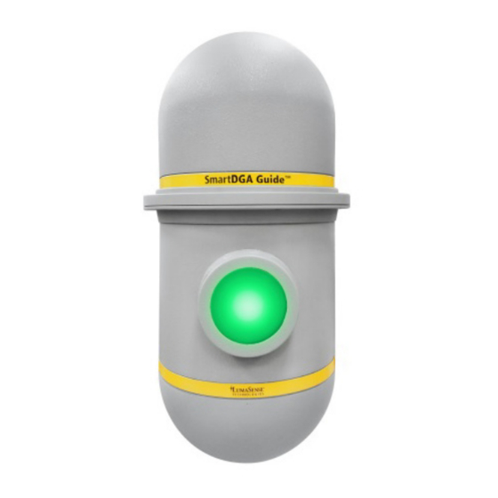
Instrument ® The indicator light on the front of the SmartDGA instrument is on for 5 seconds and off for 15 seconds, then repeats the cycle. This means that during a one minute period you have three indication cycles on the SmartDGA instrument. The LED indication light on the EZHub will be the same as on the instrument, except it will not flash and will be a solid indication. -
Page 92: Smartdga Ezhub
8.1.2 SmartDGA EZHub Controller The LED indication light on the SmartDGA EZHub controller will be the same as on the instrument, except it will not flash and will be a solid indication. The color indications are noted below. Troubleshooting • 92... - Page 93 Solid Warning indicating exceeding warning level limits set for the gas level, rate of change, or ratio Solid Alarm indicating exceeding alarm level limits set for the gas level, rate of change, or ratio Troubleshooting • 93 SmartDGA Hardware Manual...
- Page 94 To ensure consistent document formatting, this page was intentionally left blank. Troubleshooting • 94 SmartDGA Hardware Manual...
-
Page 95: Diagrams & Drawings
9 Diagrams & Drawings 9.1 Multiple SmartDGA EZHub Setup with Ethernet Hub or Switch Note: The preferred implementation is a switch, especially if the LumaSMART iCore is connected to a high traffic network. Diagrams & Drawings • 95 SmartDGA Hardware Manual... -
Page 96: Lumasmart Icore Rs485 Connections
9.2 LumaSMART iCore RS485 Connections Note: The LumaSMART iCore is optional and is not required for the SmartDGA system. Note: An Ethernet switch at the LumaSmart iCore is required to connect to both the EZHub and SCADA system using Ethernet. Use of RS485 with IEC61850 protocol will not be supported due to bandwidth restrictions. -
Page 97: Lumasmart Icore Ethernet Connections
9.3 LumaSMART iCore Ethernet Connections Note: The LumaSMART iCore is optional and is not required for the SmartDGA system. Diagrams & Drawings • 97 SmartDGA Hardware Manual... -
Page 98: Unistrut Stand
Note: The NEMA4 enclosure will heat up significantly when exposed to direct sunlight. The installation location should be chosen to minimize sunlight. If this is not possible, a sunshade over the top of the enclosure is recommended. Diagrams & Drawings • 98 SmartDGA Hardware Manual... -
Page 99: Smartdga Nema 4 Enclosure
9.5 SmartDGA NEMA 4 Enclosure Diagrams & Drawings • 99 SmartDGA Hardware Manual... -
Page 100: Inline Mounting Plate
9.6 Inline Mounting Plate Diagrams & Drawings • 100 SmartDGA Hardware Manual... -
Page 101: Wiring Connection
SmartDGA Wire Color Connector Pin EZHub Power Pin EZHub RS 485 pin (1-6 from left to right) (1-4 from left to right) Brown Yellow Black Green White Purple (Violet) Grey Blue Orange Diagrams & Drawings • 101 SmartDGA Hardware Manual... -
Page 102: Assy, Wall Mount, Smartdga Ezhub
9.8 Assy, Wall Mount, SmartDGA EZHub Diagrams & Drawings • 102 SmartDGA Hardware Manual... - Page 103 Diagrams & Drawings • 103 SmartDGA Hardware Manual...
-
Page 104: Assy, Panel Mount, Smartdga Ezhub
9.9 Assy, Panel Mount, SmartDGA EZHub Diagrams & Drawings • 104 SmartDGA Hardware Manual... - Page 105 Diagrams & Drawings • 105 SmartDGA Hardware Manual...
-
Page 106: Assy, Wall Mount, Lumasmart Icore
9.10 Assy, Wall Mount, LumaSMART iCore Diagrams & Drawings • 106 SmartDGA Hardware Manual... - Page 107 Diagrams & Drawings • 107 SmartDGA Hardware Manual...
-
Page 108: Assy, Panel Mount, Lumasmart Icore
9.11 Assy, Panel Mount, LumaSMART iCore Diagrams & Drawings • 108 SmartDGA Hardware Manual... - Page 109 Diagrams & Drawings • 109 SmartDGA Hardware Manual...
-
Page 110: Smartdga Instrument Sun Shade
9.12 SmartDGA Instrument Sun Shade Diagrams & Drawings • 110 SmartDGA Hardware Manual... - Page 111 Diagrams & Drawings • 111 SmartDGA Hardware Manual...
-
Page 112: Smartdga Instrument Dimensions
9.13 SmartDGA Instrument Dimensions 10.765” 273.43 12.152” 308.66 mm 20.918” 531.32 Diagrams & Drawings • 112 SmartDGA Hardware Manual... -
Page 113: Index
Non-Dispersive Infrared 14 Power Wiring 58, 65 Relay Outputs 58 RS485 pin 56 Wall Mount 52 Oil-Gas Separating Membrane 16 O-rings 31, 38, 43 Field Replaceable Unit 81 Filter Systems 40 Panel Mount 53 iCore 61 Index • 113 SmartDGA Hardware Manual... - Page 114 Parts 26, 35, 41, 59 Serial (RS485) Connection 64 Phoenix connectors 55 Service 8 Power 66 Single Valve 26 Power Connections 66 SmartDGA Instrument 49, 91, 93 Power Supply 58, 65, 66 Dimensions 112 Sun Shade 110 EZHub 23 Power Wiring Support 8...
Need help?
Do you have a question about the SmartDGA and is the answer not in the manual?
Questions and answers