Table of Contents
Advertisement
Quick Links
Advertisement
Table of Contents

Related Manuals for LumaSense IMPAC ISR 12-LO/GS


Summary of Contents for LumaSense IMPAC ISR 12-LO/GS
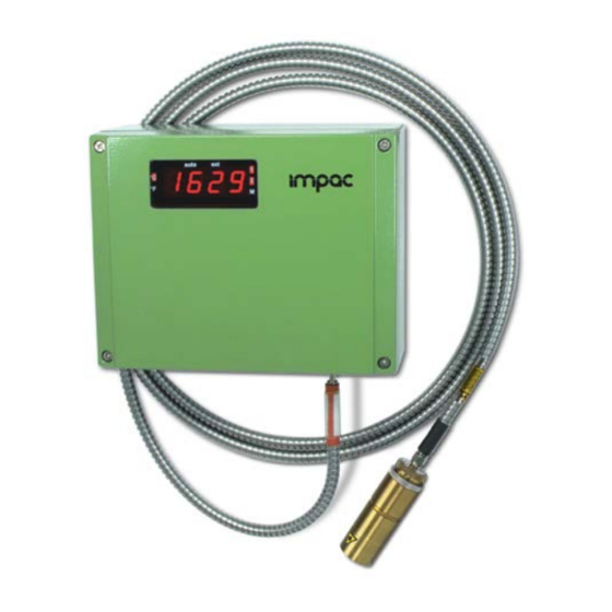
- Page 1 IMPAC Pyrometer ISR 12-LO/GS...
- Page 2 LumaSense Technologies prohibits the duplication of any portion of this manual or the use thereof for any purpose other than the operation or maintenance of the equipment described in this manual, without the express written permission of LumaSense Technologies or Advanced Energy Industries, Inc.
-
Page 3: Table Of Contents
1.3 Limit of liability and warranty ................6 1.4 Unpacking the Instrument ..................6 1.5 Service Request, Repair, or Support ............... 6 1.6 Shipments to LumaSense for Repair ..............7 1.7 Transport, Packing, Storage ..................7 1.8 Disposal / decommissioning ..................8 Introduction ........................ - Page 4 Settings / Parameter Descriptions ................. 23 4.1 Factory Settings ...................... 23 4.2 Instrument settings ....................24 4.2.1 Special indications ....................25 4.3 Pouring stream mode ..................... 25 4.4 Temperature display (°C / °F) ................. 27 4.5 Emissivity ε / emissivity slope K ................27 4.6 Exposure time (t / s) .....................
-
Page 5: General Information
1 General Information 1.1 Information about the user manual Congratulations on choosing the high quality and highly efficient IMPAC pyrometer. This manual provides important information about the instrument and can be used as a work of reference for installing, operating, and maintaining your pyrometer. It is important that you carefully read the information contained in this manual and follow all safety procedures before you install or operate the instrument. -
Page 6: Electrical Connection
LumaSense Technologies is not liable for any damages that arise from the use of any examples or processes mentioned in this manual or in case the content of this document should be incomplete or incorrect. -
Page 7: Shipments To Lumasense For Repair
Email: support@lumasenseinc.com 1.6 Shipments to LumaSense for Repair All RMA shipments of LumaSense Technologies instruments are to be prepaid and insured by way of United Parcel Service (UPS) or preferred choice. For overseas customers, ship units air- freight, priority one. -
Page 8: Disposal / Decommissioning
1.8 Disposal / decommissioning Inoperable instruments must be disposed of in compliance with local regulations for electronic materials. ISR 12-LO/GS Manual General Information • 8... -
Page 9: Introduction
2 Introduction 2.1 Appropriate use The pyrometers ISR 12-LO/GS is a special foundry system for the measurement of the pouring stream in foundries. This system is useful in automatic or semi automatic pouring machines and displays the temperature after each single pouring process. A ratio pyrometer is required for this application because •... -
Page 10: Technical Data
2.3 Technical Data Measurement Temperature Ranges: 600 ... 1300 °C (MB 13) 750 ... 1800 °C (MB 18) 900 ... 2500 °C (MB 25) Sub Range: Any range adjustable within the temperature range, minimum span 51 °C Signal processing: Photoelectric current, digitized Spectral Ranges: λ... - Page 11 Communication Analog Output: 0 … 20 mA or 4 … 20 mA switchable, load 0 … 500 Ohm Test current 10 mA by pressing test key Digital Interface: Switchable: RS232 or RS485 addressable (half duplex), baud rate 2.4 up to 115.2 kBd Display: Built-in 4-digit 7-segment-LED, height 13 mm;...
-
Page 12: Dimensions
2.4 Dimensions Pyrometer housing: Optical head: cover window Lens all dimensions in mm ISR 12-LO/GS Manual Introduction • 12... -
Page 13: Physical User Interface
2.5 Physical User Interface Pyrometer Pyrometer housing Display for clear mode Display Display °C or °F Parameter indicator LED display for temperature or parameter 10 Interface switch 11 Push button for test current Display for measuring mode 12 Setting keys Mounting screws for cover (4 units) 13 Electrical connection Fibre optic... - Page 14 Protection housing: Stainless steel (water cooling) jacket with integrated air purge unit as protection jacket for optical head protects the lens from contamination with dust and moisture. It must be supplied with dry and oil-free pressurized air (1,5 m³ / h) and generates an air stream shaped like a cone.
-
Page 15: Controls And Installation
3 Controls and Installation 3.1 Electrical Installation The ISR 12-LO/GS is powered by a voltage of 24 V DC or AC. The length of the 24 V supply line should not be longer than 30 m. Hence the use of 24 V site internal supply network is also not recommended. -
Page 16: Connector Pin J
3.1.2 Connector pin J The connector pin J can be used for 4 different functions: 1) Operating mode contact: During the warm-up of the pyrometer (after connection to the power supply, the LED display on the converter indicates “7777”) pin J is connected to the power supply voltage. -
Page 17: Connecting To Rs232 Interface
When using a converter RS485 RS232 take care, that the converter is fast enough to receive the pyrometer’s answer to an instruction of the master. Most of the commonly used converters are too slow for fast measuring equipment. So, it is recommended to use the IMPAC-converter (order no. -
Page 18: Connection Of Additional Analyzing Devices
Connection of additional analyzing devices Additional analyzing white 230 V ~ instruments, for example a Power supply 24 V LED digital display brown instrument only needs to be gree connected to a power supply °C LED digital and the analog outputs from the pyrometer. -
Page 19: Fiber Optic
3.4.2 Fiber optic Depending on the measuring range two different fibers are used. They are Fiber marked red or blue. The color mark Color mark must be mounted on the pyrometer’s side. Screw connection The fiber optic is equipped with a special connector which allows to fix the fiber only in one position. -
Page 20: Optics
3.5 Optics 3.5.1 Spot Sizes 2 different optical heads are available. They have a special spot size in shape of a line which guarantees that even a moving pouring stream can always be captured. The optical heads differ in its spot size depending on the measuring distance. The correct selection depends on the size of the pouring stream if the pouring stream is moving and the required distance to the stream. -
Page 21: Aligning The Optical Head To The Pouring Stream
3.6 Aligning the optical head to the pouring stream The optical head must be aligned in that way that the spot is partially filled by the pouring stream. If the pouring stream is moving, the stream should not leave the spot. For a correct measurement of a pouring stream it is necessary that the measuring signal has a certain minimum level of 10 to 20% (i.e. - Page 22 To ensure consistent document formatting, this page was intentionally left blank. ISR 12-LO/GS Manual Controls and Installation • 22...
-
Page 23: Settings / Parameter Descriptions
4 Settings / Parameter Descriptions All setting keys and switches for operation the instrument are placed inside the housing and can only be used after removing the cover (four screws). Ex works the instrument is operating in pouring stream mode (setting of other modes only via software InfraWin, see Chapter 5, Software InfraWin). -
Page 24: Instrument Settings
4.2 Instrument settings Display °C or °F LEDs for clear mode Parameter indicator: Measuring mode display: - mono mode - ratio mode Emissivity emissivity slope (ε / K) - metal mode Exposition time (t Clear time of maximum value storage (t Operating mode(1/2/M) Temperature- or Switch-off limit (OFF) -
Page 25: Special Indications
Measuring mode LED 1 = mono mode display LED 1 and 2 = ratio mode with additional pouring stream mode LED M = metal mode Setting keys: PAR: With the PAR button all available parameters are displayed in the following description. Pushing the button again changes the display to the next parameter, after the last parameter it changes to the actual temperature reading. - Page 26 At very short pouring times the amount of values can be reduced. E.g. if a value of 50% is adjusted, 512 measurement values must be above the beginning of temperature sub range to start the measurement of the pouring stream. Pre-run time (0 to 9.9 s): A certain pre-run time can be set in addition to the start-up condition.
-
Page 27: Temperature Display (°C / °F)
Temperature display (°C / °F) Settings: °C The temperature can be displayed in °C or °F. °F Emissivity emissivity slope K ε ε ε ε) Emissivity slope (K = ) only in ratio mode. Emissivity ( setting only in mono mode. For a correct measurement it is necessary to adjust the emissivity. -
Page 28: Exposure Time (T / S)
4.6 Exposure time (t / s) Settings: The exposure time is the time interval when the measured temperature must be present after an abrupt change so that the output value of the pyrometer 0.01 s reaches a given measurement value. The time taken is to reach 90% of the 0.05 s recorded temperature difference. - Page 29 Operation Note: Dependent on the settings the maximum value storage either works in single storage mode or in double storage mode: Single Storage The single storage is used when you want to reset the stored value using an external impulse via one contact closure from an external relay (i.e. between Mode: two measured objects).
-
Page 30: Switch-Off Limit (Off / %)
4.9 Switch-off limit (OFF / %) The switch-off limit is a function to avoid measuring errors caused by too Settings: low signals. Ratio pyrometers are able to measure temperatures correctly even with very low signals, i.e. for example through a dirty viewing window or if dust exists in the field of view or if the spot is not filled by the measuring object. -
Page 31: Baud Rate
4.13 Baud Rate Settings: The transmission rate of the serial interface in Baud (Bd) is dependent on the 2400 Bd length of the cable. A standard cable length with RS232 for 19200 Bd is 7 m, with RS485 2 km. The baud rate is reduced by 50% if the transmission 115200 Bd distance is doubled. - Page 32 To ensure consistent document formatting, this page was intentionally left blank. ISR 12-LO/GS Manual Settings / Parameter Descriptions • 32...
-
Page 33: Software Infrawin
5 Software InfraWin The operating and analyzing InfraWin software is included with delivery of the pyrometer. In addition to allowing you to make parameter adjustments via PC, the InfraWin software also provides temperature indication, data logging, and measurement analysis features. A software description can be found in the program’s help menu. - Page 34 To ensure consistent document formatting, this page was intentionally left blank. ISR 12-LO/GS Manual Software InfraWin • 34...
-
Page 35: Maintenance
6 Maintenance Safety Attention during pyrometer services: Should the pyrometer be integrated in a running machine process the machine has to be switched off and secured against restart before servicing the pyrometer. Service The pyrometer does not have any parts which require regular service, only the lens must be kept clean. - Page 36 To ensure consistent document formatting, this page was intentionally left blank. ISR 12-LO/GS Manual Maintenance • 36...
-
Page 37: Data Format Upp (Universal Pyrometer Protocol)
7 Data format UPP (Universal Pyrometer Protocol) Software commands can be exchanged directly with the pyrometer through an interface using suitable communication software or by using the “Test” function located in the “Pyrometer Parameters” window of the InfraWin software package. The data exchange occurs in ASCII format with the following transmission parameters: •... - Page 38 XX = 00 … 99; 2 digit, dec. in % dirty window: Error status: AAfs Output: XX=00…FF (00 = no error) (01…FF: error code for LumaSense service) Internal temperature: AAgt Output: XXX (dec. 000 ... 099, at °C, 032 ... 210 at °F) Max. Internal temp.: AAtm Output: XXX (dec.
- Page 39 Description Command Parameters Lock keyboard: AAlkX X = 0 ... 3 1 = lock lk1, removal with command lk0 or power off-on 0 = removal of lock lk1 3 = continuous lock lk3, removal only with command lk2 2 = removal of lock lk3 Reading parameters: AApa Output decimal 11-digit:...
- Page 40 To ensure consistent document formatting, this page was intentionally left blank. ISR 12-LO/GS Manual Data format UPP (Universal Pyrometer Protocol) • 40...
-
Page 41: Reference Numbers
12%) as well as with various optional extras. To determine the part number and the price for the desired combination please contact LumaSense or your LumaSense sales representative. A connection cable is not included in the scope of delivery and needs to be ordered separately. - Page 42 To ensure consistent document formatting, this page was intentionally left blank. ISR 12-LO/GS Manual Reference Numbers • 42...
-
Page 43: Troubleshooting
9 Troubleshooting Before sending the pyrometer for repair, try to find the error and to solve the problem with the help of the following list. Probable Cause Comments Symptom Temperature Emissivity slope set too high Set lower correct emissivity indication too low slope corresponding to the material See section 4.5... - Page 44 To ensure consistent document formatting, this page was intentionally left blank. ISR 12-LO/GS Manual Troubleshooting • 44...
-
Page 45: Index
Index Accesories 13 Language 33 Analog Output 30 Laser targeting light 18 Appropriate use 9 Legend 5 Lens contamination monitoring system 16 Liability 6 Baud Rate 31 Maintenance 35 Maximum value storage 16 Changing of optics 35 Measuring condition 25 Clear mode 24 Measuring mode 25 Clear Peak Memory 28... - Page 46 Software InfraWin 33 Spot Sizes 20 Storage Modes 28 Sub Range 30 Support 6 Switch-off limit 30 Technical Data 10 Temperature display 24, 27 Temperature sub range 25 Test current 24 Troubleshooting 43 Unpacking the Instrument 6 UPP data format 37 Wait time 31 Warranty 6 ISR 12-LO/GS Manual...
Need help?
Do you have a question about the IMPAC ISR 12-LO/GS and is the answer not in the manual?
Questions and answers