
Related Manuals for Evolution R210 MTS


Summary of Contents for Evolution R210 MTS
- Page 1 R210 Original Instructions Written in UK English Date Published: 11 / 06 / 2018...
-
Page 2: Table Of Contents
www.evolutionpowertools.com TABLE OF CONTENTS INTRODUCTION Page 3 Warranty Page 3 Machine Specification Page 4 Vibration Page 5 Labels and Symbols Page 6 Intended use of this Power Tool Page 6 Prohibited use of this Power Tool Page 6 SAFETY PRECAUTIONS Page 7 Electrical Safety Page 7... -
Page 3: Introduction
For your own safety, if you are uncertain about any aspect of using this equipment please access the relevant technical helpline, the number of which can be found on the Evolution Power Tools website. We operate several helplines throughout our worldwide organization, but technical help is also available from your supplier. -
Page 4: Machine Specification
www.evolutionpowertools.com SPECIFICATIONS MACHINE METRIC IMPERIAL Motor (230-240V~ 50 Hz) 1200W Speed No Load 3500min 3500rpm Weight 9.45kg 20lb CUTTING CAPACITIES METRIC IMPERIAL Mild Steel Plate - Max Thickness 1/8” MAXIMUM CUTTING CAPACITY (ALUMINIUM, WOOD & PVC) MITRE SAW CONFIGURATION MAX WIDTH MAX DEPTH MITRE BEVEL... -
Page 5: Vibration
BS EN ISO 5349-1:2001 and missing or damaged. Contact Evolution BS EN ISO 5349-2:2002. Power Tools for replacement labels. Note: All or some of the following symbols •... -
Page 6: Labels And Symbols
Description WARNING: This product is a Hand Operated Compound Mitre Saw and has been designed Volts to be used with special Evolution blades. Only use accessories designed for use in Amperes this machine and/or those recommended specifically by Evolution Power Tools Ltd. -
Page 7: Safety Precautions
www.evolutionpowertools.com ELECTRICAL SAFETY 1) General Power Tool (2.2) (1.14) Safety Warnings [Work area safety] This machine is fitted with the correct a) Keep work area clean and well lit. moulded plug and mains lead for the Cluttered or dark areas invite accidents. designated market. - Page 8 www.evolutionpowertools.com 3) General Power Tool Safety Warnings 4) General Power Tool Safety Warnings (2.4) (2.5) [Personal Safety]. [Power tool use and care]. a) Stay alert, watch what you are doing a) Do not force the power tool. Use the and use common sense when operating correct power tool for your application.
-
Page 9: Additional Safety Instructions
www.evolutionpowertools.com 5) General Power Tool WARNING: the operation of any power (2.6) (2.8) Safety Warnings [Service] tool can result in foreign objects being thrown a) Have your power tool serviced by a qualified towards your eyes, which could result in repair person using only identical replacement severe eye damage. - Page 10 www.evolutionpowertools.com PERSONAL PROTECTIVE Before each use check the operation of (3.6) EQUIPMENT (PPE) the retractable guard and its operating mechanism ensuring that there is no damage, Hearing protection should be worn in order and that all moving parts operate smoothly to reduce the risk of induced hearing loss.
-
Page 11: Getting Started
www.evolutionpowertools.com PERFORM CUTS WARNING: Do not use the blade guard (3.8) CORRECTLY & SAFELY as a ‘lifting point’ . The power cord must be removed from the power supply before Wherever practicable always secure the work attempting to move the machine. piece to the saw table using the work clamp where provided. - Page 12 ADDITIONAL ACCESSORIES (4.2) (4.3) In addition to the standard items supplied with this machine the following accessories Description Quantity are also available from the Evolution online shop at www.evolutionpowertools.com or Instruction Manual from your local retailer. (4.4) Hold Down Clamp Description...
-
Page 13: Machine Overview
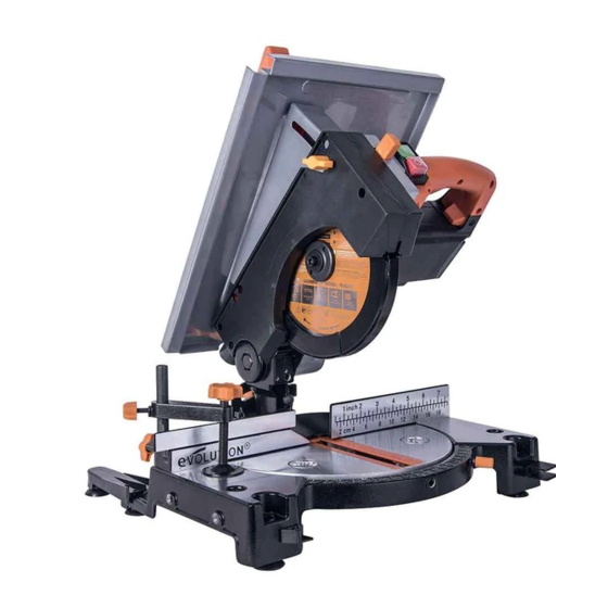
www.evolutionpowertools.com R210MTS MITRE SAW CONFIGURATION 1. CUTTING HANDLE 7. MITRE ANGLE SCALE 2. ROTARY TABLE 8. FENCE 3. RETRACTABLE LOWER BLADE GUARD 9. HOLD DOWN CLAMP 4. BLADE 10. STABILISING ARMS (X2 Back of machine) 5. BEVEL LOCKING LEVER 11. CUTTING HEAD RELEASE LEVER (Back of the machine) 6. -
Page 14: Service Parts Diagram
www.evolutionpowertools.com R210MTS TABLE SAW CONFIGURATION 1. ON/OFF TRIGGER SWITCH (Inside handle) 7. RIP FENCE 2. ON/OFF LATCHING SWITCHES 8. PUSH STICK 3. CUTTING HANDLE 9. MOUNTING HOLE (2 at the front and 2 under the stabilising arms) 4. TABLE TOP 10. -
Page 15: Assembly And Preparation
www.evolutionpowertools.com GETTING STARTED WARNING: ALWAYS DISCONNECT THE SAW FROM THE POWER SOURCE BEFORE MAKING ANY ADJUSTMENTS. Refer to the “Service Parts Diagram”. Install a blade as detailed in the “Installing or Removing the Blade” section. Note: We recommend that the operator reads the ‘Important Information’... - Page 16 www.evolutionpowertools.com To fit the Stabilising Arms: • Remove the cross head machine screws from the two (2) rear mounting positions. • Attach the Stabilising Arms with the machine screws, two per arm and tighten securely. Note: The Stabilising Arms are fitted with rubber feet. The base of the R210MTS is also fitted with four (4) identical rubber feet positioned underneath the mounting holes in the base.
- Page 17 www.evolutionpowertools.com TO CONFIGURE THE R210MTS FOR USE AS A MITRE SAW WARNING: Only carry out this procedure with the machine disconnected from the power source. Caution: The R210MTS has many built in safety features and safety interlocks. It is important that the following instructions, and those found on the label attached to the machine table are read, understood and acted upon.
-
Page 18: Operating Instructions
www.evolutionpowertools.com HOLD DOWN CLAMP (Fig. 9) A Hold Down clamp is supplied with the R210MTS. Two sockets (one on either side) are incorporated into the rear of the machines fence. • Fit the pillar of the clamp into the socket that best suits the cutting application, ensuring that it is pushed fully down. - Page 19 www.evolutionpowertools.com 2. Preparing to make a cut • Avoid awkward operations and hand positions where a sudden slip could cause fingers or hands to move into the blade. • Cut only one workpiece at a time. • Clear everything except the workpiece and related support devices away from the blade before commencing operations.
- Page 20 www.evolutionpowertools.com • After the cut is completed, turn off the motor by releasing the trigger switch. Allow the blade to come to a complete stop. Allow the Cutting Head to rise to its upper position. • Only remove your hands or the workpiece from the machine when the Cutting Head is in its upper position with the blade teeth completely covered by the Retractable Blade Guard.
- Page 21 www.evolutionpowertools.com so that the path of the blade can be checked. Some Bevel and Compound Cuts may require the Hold Down Clamp to be positioned to the RH side of the Cutting Head. This may be necessary to avoid interference with the blade and other parts of the machine as the Cutting Head is lowered.
- Page 22 www.evolutionpowertools.com 10. Cutting Bowed Material (Fig 15) Before cutting any workpiece, check to see if it is bowed. If it is bowed the workpiece must be positioned and cut as shown. Do not position the workpiece incorrectly or cut the workpiece without the support of the fence.
- Page 23 www.evolutionpowertools.com FENCE ASSEMBLY (Fig. 19) The Fence Assembly consists of two (2) main parts: • The Angle Gauge. • The Rip Fence Face Plate. Note: The ‘T’ slot in the Rip Fence Face Plate is not centrally located. height • Slide the Rip Fence Face Plate onto the two (2) mounting screws found on the Angle Plate.
- Page 24 www.evolutionpowertools.com BASIC TABLE SAW OPERATIONS WARNING: Do not cut metal or metallic materials when the machine is configured as a Table Saw. WARNING: Never attempt freehand cuts on this machine. Always use a correctly adjusted Rip Fence to minimise the possibility of the blade binding and kickback.
-
Page 25: Maintenance
www.evolutionpowertools.com Note: Check that the Rip Fence is locked in position and is parallel to the saw blade. Check that the riving knife is properly aligned with the saw blade. When ripping small section material a Push Stick should be used to feed/guide the final 300mm of the material past the blade. - Page 26 (Fig. 27) slightly using an allen key. When correct alignment is achieved tighten the fixing screws. Note: Use only a genuine Evolution Riving Knife, as this is a dedicated component for this machine. Non genuine parts could be dangerous. If in any doubt, please contact the Helpline.
- Page 27 www.evolutionpowertools.com To change a blade: • Ensure that the machine is in Mitre Saw Mode with the Cutting Head in its upper position. • Release the Retractable Lower Guard Operating Lever by removing and safely storing its pivot screw. (Fig. 28) •...
- Page 28 www.evolutionpowertools.com CHECKING AND SETTING OF BEVEL ANGLES WARNING: Before making any adjustments ensure that the machine is disconnected from the power supply. Note: While all angular settings have been factory set, checking and adjustment may be required as a consequence of normal operational wear and tear.
- Page 29 www.evolutionpowertools.com To check: • Ensure that the Cutting Head is tilted to the 45˚ position, against its stop, with the Bevel Pointer indicating 45˚ Bevel Angle. • Tighten the Bevel Lock Handle. • Lower the Cutting Head to its lowest position. The Retractable Lower Blade Guard will rotate up into the machine.
-
Page 30: Environmental Protection
www.evolutionpowertools.com FUSE AND PLUG REPLACEMENT (230V Only) Should the fuse in the main plug of your machine need replacing it should always be replaced with one of identical rating. Check the voltage given on your machine matches the supply voltage. This machine is supplied with a fitted moulded plug. -
Page 31: Declaration Of Conformity
In accordance with EN ISO 17050-1:2004 The manufacturer of the product covered by this Declaration is: Evolution Power Tools, Venture One, Longacre Close, Holbrook Industrial Estate, Sheffield, S20 3FR The manufacturer hereby declares that the machine as detailed in this declaration fulfils all the relevant provisions of the Machinery Directive and other appropriate directives as detailed below. - Page 32 Evolution Power Tools Ltd Evolution Power Tools LLC Evolution Power Tools SAS Venture One 8363 Research Drive 61 Avenue Lafontaine Longacre Close Davenport 33560 Holbrook Industrial Estate Iowa Carbon-Blanc Sheffield 52806 Bordeaux S20 3FR +44 (0)114 251 1022 +1 866-EVO-TOOL...
Need help?
Do you have a question about the R210 MTS and is the answer not in the manual?
Questions and answers