Table of Contents
Advertisement
Available languages
Available languages
Quick Links
Advertisement
Table of Contents

Subscribe to Our Youtube Channel
Related Manuals for Evolution R210 MTS G2


Summary of Contents for Evolution R210 MTS G2
- Page 1 Original Instructions Originalbetriebsanleitung Instrucciones Originales Instructions Originales Notice Originale Oryginalna Instrukcja Originele Instructies Written in UK English Date Published: 08/02/2022...
- Page 2 For your own safety, if you are uncertain about any aspect of using this equipment please access the relevant technical helpline, the number of which can be found on the Evolution Power Tools website. We operate several helplines throughout our worldwide organization, but technical help is also available from your supplier.
-
Page 3: Specifications
www.evolutionpowertools.com SPECIFICATIONS MACHINE UK/EU Motor (220-240V~ 50 Hz) 1500W Speed No Load 3800 min Weight 13kg CUTTING CAPACITIES UK/EU Mild Steel Plate - Max. Thickness Mild Steel Plate - Max. Hardness 210HB MAXIMUM CUTTING CAPACITY (ALUMINIUM, WOOD & PVC) MITRE SAW CONFIGURATION BEVEL MITRE UK/EU... -
Page 4: Labels And Symbols
(EN 61029-1, EN 61029-2-11) and may if warning and/or instruction labels are be used for comparing one tool with another. missing or damaged. Contact Evolution Power Tools for replacement labels. WARNING: The noise emission during actual Note: All or some of the following symbols... -
Page 5: Electrical Safety
Compound Mitre Saw and has been designed The manufacturers instructions should be to be used with special Evolution blades. followed when using an extension cable. Only use accessories designed for use in... -
Page 6: Health Advice
www.evolutionpowertools.com • The upper saw blade guard has to be not be distracted. lowered over the workpiece for each cut. • Note the direction of rotation of the motor • Be sure to use a push stick when slitting and saw blade. narrow workpieces smaller than 120 mm in •... -
Page 7: Blade Safety
www.evolutionpowertools.com WARNING: the operation of any power tool can practicable. It is not advisable to wear gloves result in foreign objects being thrown towards when operating the mitre saw. your eyes, which could result in severe eye damage. Before beginning power tool operation, SAFE OPERATION always wear safety goggles or safety glasses with Always ensure that you have selected the correct... - Page 8 www.evolutionpowertools.com PERFORM CUTS CORRECTLY & SAFELY WARNING: Do not use the blade guard as a Wherever practicable always secure the work ‘lifting point’ . The power cord must be removed piece to the saw table using the work clamp from the power supply before attempting to where provided.
-
Page 9: Getting Started - Unpacking
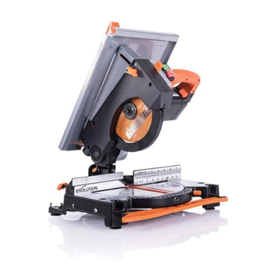
Take care when unpacking. Remove the machine, this machine the following accessories are also together with the accessories supplied from the available from the Evolution online shop at packaging. Check carefully to ensure that the www.evolutionpowertools.com or from your machine is in good condition and account for all local retailer. - Page 10 www.evolutionpowertools.com R210MTS-G2 MACHINE OVERVIEW 1. CUTTING HANDLE 2. ROTARY TABLE 3. RETRACTABLE LOWER BLADE GUARD 4. MITRE ANGLE LOCKING HANDLE 5. MITRE ANGLE SCALE 6. CUTTING HEAD RELEASE LEVER 7. CUTTING HEAD LOCK DOWN PIN 8. PUSH STICK STORAGE 9. TABLE SAW ON/OFF SWITCH 10.
- Page 11 www.evolutionpowertools.com R210MTS-G2 MACHINE OVERVIEW 1. TABLE TOP 2. TABLE SAW GUARD 3. RIP FENCE 4. PUSH STICK 5. TABLE/MITRE MODE PIN 6. BEVEL LOCKING LEVER 7. REAR STABILISING ARM 8. WORKPIECE SUPPORTS (X2) 9. TOOL STORAGE 10. RIP FENCE LOCKING LEVERS (X2) 11.
-
Page 12: Getting Started
• Fit the table saw guard assembly (Fig.3) • Tighten the 2 hex screws INSTALLING/REMOVING BLADE WARNING: Only use genuine Evolution blades which are designed for use in this machine. Ensure that the maximum speed of the blade is compatible with the machine. Only perform this operation with the machine disconnected from the mains supply. - Page 13 To adjust the Riving Knife loosen the two fixing screws (Fig. 9) slightly using an allen key. When correct alignment is achieved tighten the fixing screws. Note: Use only a genuine Evolution upper blade guard assembly, Fig. 6 as this is a dedicated component for this machine. Non genuine parts could be dangerous.
-
Page 14: Hold Down Clamp
www.evolutionpowertools.com WORKPIECE SUPPORTS Workpiece supports must be fitted to both sides of the machine (Fig.10) HOLD DOWN CLAMP A Hold Down clamp is supplied with the R210MTS-G2. Two sockets (one on either side) are incorporated into the rear of the machines fence. (Fig. 11) •... - Page 15 www.evolutionpowertools.com 3. The Mitre Saw On/Off Trigger Switch Operation Operate the switch to turn on the machines motor. Release the switch to turn off the machines motor. (Fig. 14) 4. Chop Cutting The Cutting Head is gently pushed down to cut through the workpiece.
- Page 16 www.evolutionpowertools.com To set a Bevel Angle: • Loosen the bevel lock handle • Tilt the cutting head to the desired angle. Use the protractor guide to aid with setting. • Ensure that the bevel lock handle is securely tightened when the desired angle has been achieved. A bevel cut can now be made using the same techniques as previously outlined.
-
Page 17: Basic Table Saw Operations
www.evolutionpowertools.com FENCE ASSEMBLY AS A RIP FENCE To use the Fence Assembly as a Rip Fence the Face Plate must be accurately aligned with the blade. WARNING: Only carry out this procedure with the machine disconnected from the power supply. To Align the Rip Fence: •... -
Page 18: Bevel Angle
www.evolutionpowertools.com CHECKING AND SETTING OF BEVEL ANGLES WARNING: Before making any adjustments ensure that the machine is disconnected from the power supply. Note: While all angular settings have been factory set, checking and adjustment may be required as a consequence of normal operational wear and tear. -
Page 19: Maintenance And Adjustments
www.evolutionpowertools.com If adjustment is required: Note: The Cutting Head will need to be tilted to gain access to the 45˚ Bevel Stop Adjustment Screw. • Loosen slightly the 45˚ Bevel Stop Adjustment Screw locknut. (Fig. 23) • Use a Hex Key to turn the Bevel Stop Screw clockwise or counterclockwise as required. -
Page 20: Ec Declaration Of Conformity
EC DECLARATION OF CONFORMITY The manufacturer of the product covered by this Declaration is: UK: Evolution Power Tools Ltd. Venture One, Longacre Close, Holbrook Industrial Estate, Sheffield, S20 3FR. FR: Evolution Power Tools SAS. 61 Avenue Lafontaine, 33560, Carbon-Blanc, Bordeaux, France. - Page 21 EC DECLARATION OF CONFORMITY The manufacturer of the product covered by this Declaration is: UK: Evolution Power Tools Ltd. Venture One, Longacre Close, Holbrook Industrial Estate, Sheffield, S20 3FR. FR: Evolution Power Tools SAS. 61 Avenue Lafontaine, 33560, Carbon-Blanc, Bordeaux, France.
-
Page 22: Garantie
UK:customer.services@evolutionpowertools.com USA: evolutioninfo@evolutionpowertools.com GARANTIE Wir gratulieren Ihnen zum Kauf einer Maschine von Evolution Power Tools. Folgen Sie den Anweisungen des beliegenden Merkblattes und registrieren Sie Ihr Produkt „online“. Hierdurch aktivieren Sie die Garantiefrist Ihrer Maschine über die Evolution-Website. Geben Sie zu diesem... -
Page 23: Technische Daten
www.evolutionpowertools.com TECHNISCHE DATEN MASCHINE GB/EU Motor (220–240 V ~ 50 Hz) 1500 W Leerlaufgeschwindigkeit 3800 min Gewicht 13 kg SCHNITTLEISTUNG GB/EU Baustahlplatte - max. Stärke 3 mm Baustahlplatte - max. Stärke 210 HB MAXIMALE SCHNITTLEISTUNG (ALUMINIUM, HOLZ UND PVC) KONFIGURATION DER GEHRUNGSSÄGE GEHRUNG NEIGUNG GB/EU 0°... - Page 24 Prüfmethode (EN 61029-1, EN 61029-2-11) nicht, wenn Warnhinweise und/oder gemessen und können verwendet werden, Hinweisschilder fehlen oder beschädigt sind. um verschiedene Maschinen miteinander zu Für Ersatz wenden Sie sich an Evolution Power vergleichen. Tools. WARNUNG: Die Geräuschemissionen, die Hinweis: Manche oder alle der bei der Verwendung des Elektrowerkzeugs folgenden Symbole können in der...
- Page 25 Wenn ein Verlängerungskabel erforderlich ist, Maschine entwickeltes und/oder ausdrücklich von muss es für die Verwendung im Freien geeignet Evolution Power Tools Ltd empfohlenes Zubehör. und entsprechend gekennzeichnet sein. Bei Verwendung eines Verlängerungskabels sind die Mit geeignetem Sägeblatt kann diese Maschine Anweisungen des Herstellers zu beachten.
- Page 26 www.evolutionpowertools.com Schützen Sie das Kabel von Hitze, Öl und Inbetriebnahme der Maschine, dass die auf scharfen Kanten. dem Typenschild angegebene Spannung • Wir empfehlen bei der Arbeit im Freien das mit der Netzspannung übereinstimmt. Tragen von rutschfesten Schuhen. • Wenn Sie ein Verlängerungskabel •...
-
Page 27: Persönliche Schutzausrüstung (Psa)
www.evolutionpowertools.com Ziehen Sie dazu den Netzstecker und Verletzungen und dem Verlust von Gliedmaßen schwenken Sie das Sägeblatt von Hand führen. Halten Sie Finger und Hände immer in die 45°- und 90°-Stellung. Stellen Sie mindestens 150 mm vom Sägeblatt entfernt. gegebenenfalls den Sägekopf neu ein. Versuchen Sie niemals, das Sägematerial •... - Page 28 www.evolutionpowertools.com Achten Sie beim Transport der Gehrungssäge beschrieben. darauf, dass der Schneidkopf in der 90°-Position Lange Werkstücke sollten durch die nach unten verriegelt ist (bei einer Gleit- bereitgestellten Arbeitshilfen oder auf Gehrungssäge, dass die Gleitstangen verriegelt entsprechenden zusätzlichen Arbeitshilfen sind). Heben Sie das Gerät an, indem Sie die gestützt werden.
-
Page 29: Zusätzliches Zubehör
Arbeitsfläche und überprüfen Sie die Säge Neben den im Lieferumfang dieser Maschine sorgfältig. enthaltenen Standardartikeln sind zudem die folgenden Zubehörteile über den Evolution- Überprüfen Sie insbesondere die Funktion aller Online-Shop unter Sicherheitsvorrichtungen der Maschine, bevor Sie www.evolutionpowertools.com oder bei Ihrem die Maschine in Betrieb nehmen. - Page 30 www.evolutionpowertools.com R210MTS-G2 MASCHINENÜBERSICHT 1. SCHNEIDGRIFF 2. DREHTISCH 3. EINZIEHBARER UNTERER SÄGEBLATTSCHUTZ 4. GEHRUNGSWINKEL-FESTSTELLGRIFF 5. GEHRUNGSWINKELSKALA 6. SCHNEIDKOPF-FREIGABEHEBEL 7. SPERRSTIFT FÜR SCHNEIDKOPF 8. SCHUBSTANGENABLAGE 9. TISCHKREISSÄGE EIN/AUS-SCHALTER 10. GEHRUNGSSÄGE EIN/AUS-SCHALTER...
- Page 31 www.evolutionpowertools.com R210MTS-G2 MASCHINENÜBERSICHT 1. TISCHOBERSEITE 2. TISCHSÄGENSCHUTZ 3. PARALLELANSCHLAG 4. SCHUBSTANGE 5. PIN FÜR TISCH-/GEHRUNGSMODUS 6. NEIGUNGSWINKEL-SPERRHEBEL 7. HINTERER STABILISIERUNGSARM 8. WERKSTÜCKTRÄGER (X2) 9. WERKZEUGABLAGE 10. PARALLELANSCHLAG-SPERRHEBEL (X2) 11. BREITE DER ARBEITSPLATTE...
-
Page 32: Erste Schritte
• Montieren Sie die Schutzvorrichtung der Tischkreissäge (Abb.3) • Ziehen Sie die 2 Sechskantschrauben fest MONTAGE/DEMONTAGE DES SÄGEBLATTS WARNUNG: Verwenden Sie nur originale Sägeblätter von Evolution, die für den Einsatz in dieser Maschine konzipiert wurden. Stellen Sie sicher, dass die maximale Drehzahl des Sägeblattes mit der Maschine kompatibel ist. - Page 33 (Abb. 9) ein wenig mit einem Sechskantschlüssel. Ist die korrekte Ausrichtung erreicht, ziehen Sie die Feststellschrauben an. Abb. 6 Hinweis: Verwenden Sie nur ein Evolution-Originalteil für den oberen Blattschutz, da es sich um ein spezielles Bauteil für diese Maschine handelt. Die Verwendung von Teilen, die keine Originalteile sind, kann gefährlich sein.
- Page 34 www.evolutionpowertools.com WERKSTÜCKTRÄGER Werkstückträger müssen an beiden Seiten der Maschine angebracht werden (Abb. 10) NIEDERHALTERKLEMME Im Lieferumfang der R210MTS-G2 ist eine Niederhalterklemme enthalten. In die Rückseite des Maschinenanschlags sind zwei Halterungen (eine auf jeder Seite) eingefasst. (Abb. 11) • Stecken Sie die Klemme in den für die Schneidanwendung am Abb.
- Page 35 www.evolutionpowertools.com 3. Betrieb des Ein/Aus-Schalters der Gehrungssäge Betätigen Sie den Schalter, um den Motor der Maschine einzuschalten. Lassen Sie den Schalter los, um den Motor der Maschine auszuschalten. (Abb. 14) 4. Kappschnitt Der Schneidkopf wird vorsichtig nach unten gedrückt, um das Werkstück zu schneiden. •...
- Page 36 www.evolutionpowertools.com • Stellen Sie sicher, dass der Verriegelungsgriff für die Neigung wieder festgezogen ist, sobald der gewünschte Winkel ausgewählt wurde. Ein Neigungsschnitt kann nun mit denselben Techniken durchgeführt werden, wie sie zuvor beschrieben wurden. Hinweis: Führen Sie immer einen „Trockenlauf“ bei ausgeschalteter Maschine durch, damit der Weg des Sägeblatts überprüft werden kann.
- Page 37 www.evolutionpowertools.com PARALLELANSCHLAG MIT MONTIERTEM ANSCHLAG Um die Anschlageinheit als Parallelanschlag zu verwenden, muss die Planscheibe genau auf das Sägeblatt ausgerichtet sein. WARNUNG: Dieser Vorgang darf nur bei getrennter Hauptstromversorgung durchgeführt werden. So richten Sie den Parallelanschlag aus: • Stellen Sie die Neigung mit Hilfe der Tischmaßskala auf 0˚ ein. •...
- Page 38 www.evolutionpowertools.com KONTROLLE UND EINSTELLUNG DES NEIGUNGSWINKELS WARNUNG: Vergewissern Sie sich vor der Durchführung von Einstellungen, dass die Maschine von der Stromversorgung getrennt ist. Hinweis: Obwohl alle Winkeleinstellungen werksseitig vorgenommen wurden, kann eine Überprüfung und Anpassung infolge normaler betrieblicher Abnutzung erforderlich sein. Hinweis: Zum Prüfen und Einstellen der Neigungswinkel muss sich die Maschine in der Konfiguration Gehrungssäge befinden.
- Page 39 www.evolutionpowertools.com Falls eine Anpassung erforderlich ist: Hinweis: Der Schneidkopf muss geneigt werden, um Zugang zur Einstellschraube des 45°-Neigungswinkelanschlags zu erhalten. • Lösen Sie die Feststellmutter der Einstellschraube für den 45°-Neigungswinkelanschlag leicht. (Abb. 23) • Verwenden Sie einen Sechskantschlüssel, um die Neigungswinkel-Anschlagschraube je nach Bedarf im oder gegen den Uhrzeigersinn zu drehen.
-
Page 40: Eg-Konformitätserklärung
EG-KONFORMITÄTSERKLÄRUNG Der Hersteller des von dieser Konformitätserklärung gedeckten Produktes ist: UK: Evolution Power Tools, Venture One, Longacre Close, Holbrook Industrial Estate, Sheffield, S20 3FR. FR: Evolution Power Tools SAS. 61 Avenue Lafontaine, 33560, Carbon-Blanc, Bordeaux, Frankreich. Hiermit erklärt der Hersteller, dass die Maschine wie in dieser Erklärung dargestellt allen relevanten Auflagen der Maschinenrichtlinie und anderer betreffender weiter unten ausgeführten Richtlinien entspricht. - Page 41 www.evolutionpowertools.com...
- Page 42 De esta manera, validará el periodo de garantía de su máquina a través de la página web de Evolution al introducir sus datos y, así, dispondrá de un servicio rápido si fuera necesario. Le agradecemos sinceramente que haya escogido un producto de Evolution Power Tools.
-
Page 43: Especificaciones
www.evolutionpowertools.com ESPECIFICACIONES MÁQUINA REINO UNIDO/UE Motor (220-240 V ~ 50 Hz) 1500 W Velocidad sin carga 3800 min Peso 13 kg CAPACIDADES DE CORTE REINO UNIDO/UE Placa de acero suave, grosor máximo 3 mm Placa de acero suave, dureza máxima 210 HB MÁXIMA CAPACIDAD DE CORTE (ALUMINIO, MADERA Y PVC) CONFIGURACIÓN DE LA SIERRA INGLETADORA AJUSTE INGLETE... -
Page 44: Etiquetas Y Símbolos
2-11) y pueden usarse para comparar una advertencia, o si están dañadas. Póngase en herramienta con otra. contacto con Evolution Power Tools para sustituir las etiquetas. ADVERTENCIA: la emisión de ruido al usar la herramienta eléctrica puede diferir del valor... -
Page 45: Uso Previsto De Esta Herramienta Eléctrica
(RCD) antes de utilizar la máquina. de Evolution. Utilice solamente accesorios Si se necesita un alargador, debe ser de un diseñados para el uso de esta máquina y/o tipo adecuado para uso en exteriores y estar aquellos recomendados específicamente por... - Page 46 www.evolutionpowertools.com • Una zona de trabajo desordenada puede todo el cable de la bobina. causar accidentes. • Nunca transporte la sierra mediante su • No deje que otras personas, sobre todo cable. niños, toquen la herramienta ni el cable de •...
-
Page 47: Consejos Para La Salud
www.evolutionpowertools.com CONSEJOS PARA LA SALUD el fabricante, como se detalla en este manual y ADVERTENCIA: durante el uso de esta máquina, que cumplan los requisitos de la norma se pueden producir partículas de polvo. A veces, EN 847-1. según los materiales con los que trabaje, este polvo puede ser especialmente perjudicial. - Page 48 www.evolutionpowertools.com CONSEJOS DE SEGURIDAD ADICIONALES Antes de cada uso, compruebe el funcionamiento de la protección retráctil y su mecanismo de TRANSPORTAR LA SIERRA INGLETADORA DE MESA funcionamiento. Asegúrese de que no haya daños y de que todas las piezas móviles funcionen de Consejos de seguridad forma fluida y correcta.
-
Page 49: Primeros Pasos: Desembalaje
Compruebe que la máquina está en buenas encontrará en la tienda en línea de Evolution en condiciones y que se incluyen todos los www.evolutionpowertools.com o en su accesorios especificados en este manual. - Page 50 www.evolutionpowertools.com DESCRIPCIÓN GENERAL DE LA MÁQUINA R210MTS-G2 1. MANGO DE CORTE 8. ALMACENAMIENTO DEL EMPUJADOR INTERRUPTOR DE ENCENDIDO/APAGADO 2. MESA GIRATORIA DE LA SIERRA DE MESA 3. PROTECCIÓN INFERIOR RETRÁCTIL DE LA 10. GATILLO DE ENCENDIDO/APAGADO DE HOJA LA INGLETADORA 4.
- Page 51 www.evolutionpowertools.com DESCRIPCIÓN GENERAL DE LA MÁQUINA R210MTS-G2 1. PARTE SUPERIOR DE LA MESA 2. PROTECCIÓN DE LA SIERRA DE MESA 3. TOPE GUÍA 4. EMPUJADOR 5. SEGURO DEL MODO DE MESA/INGLETE 6. PALANCA DE BLOQUEO DEL BISEL 7. BRAZO ESTABILIZADOR TRASERO SOPORTES DE LA PIEZA DE TRABAJO (X2) ALMACENAMIENTO DE HERRAMIENTAS 10.
-
Page 52: Primeros Pasos
• Instale el conjunto de la protección de la sierra de mesa (Fig.3) • Apriete los 2 tornillos hexagonales INSTALACIÓN/RETIRADA DE LA HOJA ADVERTENCIA: utilice solo hojas Evolution originales que hayan sido diseñadas para su uso en esta máquina. Asegúrese de que la velocidad máxima de la hoja es compatible con la máquina. - Page 53 Nota: use únicamente un conjunto de protección superior Fig. 6 de la hoja original de Evolution, ya que es un componente específico para esta máquina. Las piezas no originales podrían ser peligrosas. En caso de duda, contacte con el servicio de asistencia técnica.
- Page 54 www.evolutionpowertools.com MORDAZA DE SUJECIÓN Se suministra una mordaza de sujeción con la R210MTS-G2. Se incorporan dos cavidades (una a cada lado) en la parte posterior de la guía de la máquina. (Fig. 11) • Encaje el pilar de la mordaza en la cavidad que mejor se adapte a la aplicación de corte, asegurándose de que esté...
- Page 55 www.evolutionpowertools.com 4. Corte de tronzado La cabeza de corte se empuja suavemente hacia abajo para cortar la pieza de trabajo. • Coloque la pieza de trabajo sobre la mesa giratoria y contra la guía en la posición deseada. Asegure con mordaza(s) según sea apropiado.
- Page 56 www.evolutionpowertools.com técnicas que se describen previamente. Nota: realice siempre una prueba con la máquina desconectada para que se pueda comprobar el recorrido de la hoja. Algunos cortes compuestos y de bisel pueden requerir que la mordaza de sujeción se sitúe en el lado derecho de la cabeza de corte. Esto puede ser necesario para evitar la interferencia con la hoja y otras piezas de la máquina cuando se baja la cabeza de corte.
- Page 57 www.evolutionpowertools.com Para alinear el tope guía: • Ajuste el bisel a 0˚ usando las escalas de medición de la mesa. • Alinee el tope usando las escalas de la superficie de la mesa y bloquéelo en posición con las 2 palancas de bloqueo. OPERACIONES BÁSICAS DE LA SIERRA DE MESA ADVERTENCIA: no corte metal ni materiales metálicos cuando la máquina esté...
- Page 58 www.evolutionpowertools.com Nota: para comprobar y ajustar los ángulos de bisel, la máquina debe estar en la configuración de sierra ingletadora. ÁNGULO DE BISEL DE 0° A un ángulo de bisel de 0°, la hoja debería estar perpendicular y a exactamente 90° de la mesa giratoria. Se necesita una escuadra de ingeniero precisa (no suministrada) para comprobar el ángulo de bisel de 0°.
-
Page 59: Mantenimiento Y Ajustes
www.evolutionpowertools.com Si se requiere el ajuste: Nota: la cabeza de corte tendrá que estar inclinada para poder acceder al tornillo de ajuste del tope del bisel de 45°. • Afloje ligeramente la contratuerca del tornillo de ajuste del tope del bisel de 45°. (Fig. 23) •... -
Page 60: Declaración De Conformidad Ce
DECLARACIÓN DE CONFORMIDAD CE El fabricante del producto incluido en esta Declaración es el siguiente: Reino Unido: Evolution Power Tools Ltd., Venture One, Longacre Close, Holbrook Industrial Estate, Sheffield, S20 3FR (Reino Unido). FR: Evolution Power Tools SAS. 61 Avenue Lafontaine, 33560, Carbon-Blanc, Burdeos (Francia). - Page 61 www.evolutionpowertools.com...
-
Page 62: Site Internet
« en ligne » comme expliqué dans le dépliant fourni avec cet appareil. Cela vous permettra de valider la période de garantie de l'appareil via le site Internet d’Evolution en saisissant vos coordonnées, ce qui vous garantit un service rapide si nécessaire. -
Page 63: Caractéristiques
www.evolutionpowertools.com CARACTÉRISTIQUES APPAREIL RU/UE Moteur (220-240 V ~ 50 Hz) 1500 W Vitesse à vide 3800 min Poids 13 kg CAPACITÉS DE COUPE RU/UE Plaque en acier doux - Épaisseur max. 3 mm Plaque en acier doux - Dureté max. 210 HB CAPACITÉ DE COUPE MAXIMALE (ALUMINIUM, BOIS ET PVC) CONFIGURATION DE LA SCIE À... -
Page 64: Étiquettes Et Symboles
étiquettes d’avertissement et/ou de 2-11) et peuvent être utilisées pour comparer consignes sont manquantes ou endommagées. plusieurs outils. Contactez Evolution Power Tools pour le remplacement des étiquettes. AVERTISSEMENT : Les émissions sonores durant l'utilisation effective de l'outil électrique peuvent Remarque : Tous les symboles suivants ou... -
Page 65: Usage Prévu De Cet Outil Électrique
(DCR) avant d’utiliser l'appareil. recommandés par Evolution Power Tools Ltd. Si vous devez utiliser une rallonge, celle-ci doit convenir à l’utilisation en extérieur et Cet appareil, lorsqu'il est équipé d'une lame cette mention doit figurer sur l’étiquette. - Page 66 www.evolutionpowertools.com • chaussures antidérapantes lorsque vous Si vous devez utiliser une rallonge, travaillez à l'extérieur. assurez-vous que la section transversale • Maintenez les cheveux longs dans un filet de ses conducteurs est suffisante pour la à cheveux. consommation électrique de la scie. Section •...
- Page 67 www.evolutionpowertools.com dispositifs utilisés pour couvrir la lame sont peuvent provoquer des blessures graves et une en bon état de fonctionnement. amputation. N’approchez jamais vos doigts et • Ne calez jamais le capot de protection à vos mains à moins de 150 mm de la lame, quelles charnière en position ouverte.
- Page 68 www.evolutionpowertools.com matériaux autres que ceux mentionnés dans ce Si besoin, vous pouvez monter la scie à onglet mode d’emploi. sur une base ou un établi en bois, ou bien de la fixer à un support pour scie à onglets, comme Lors du transport d'une scie à...
-
Page 69: Accessoires Complémentaires
En plus des articles standards fournis avec cet base de l'appareil, pour le transporter. appareil, vous trouverez les accessoires suivants dans la boutique en ligne d’Evolution sur Placez la scie sur une surface de travail fixe www.evolutionpowertools.com ou chez votre et sûre et vérifiez soigneusement le dessus... - Page 70 www.evolutionpowertools.com PRÉSENTATION DE L'APPAREIL R210MTS-G2 1. POIGNÉE DE COUPE INTERRUPTEUR MARCHE/ARRÊT DE LA SCIE SUR TABLE 2. PLATEAU ROTATIF 10. GÂCHETTE MARCHE/ARRÊT DE LA SCIE 3. CARTER DE LAME INFÉRIEUR À ONGLET RÉTRACTABLE 4. POIGNÉE DE VERROUILLAGE DE L'ANGLE D'ONGLET 5.
- Page 71 www.evolutionpowertools.com PRÉSENTATION DE L'APPAREIL R210MTS-G2 1. HAUT DE LA TABLE 2. PROTECTION POUR SCIE SUR TABLE 3. GUIDE DE REFEND 4. POUSSOIR 5. BROCHE DE MODE TABLE/ONGLET 6. LEVIER DE VERROUILLAGE DU BISEAU 7. BRAS STABILISATEUR ARRIÈRE SUPPORT DE PIÈCE À USINER (X2) RANGE-OUTILS 10.
-
Page 72: Prise En Main
• Montez l'ensemble de protection de la scie à table (Ill.3) • Serrez les 2 vis hexagonales INSTALLATION/RETRAIT DE LA LAME AVERTISSEMENT : N'utilisez que des lames Evolution conçues spécialement pour être utilisées dans cet appareil. Assurez-vous que la vitesse maximale de la lame est compatible avec l'appareil. - Page 73 Remarque : Utilisez uniquement un protège-lame supérieur Ill. 6 Evolution d'origine, car il s'agit d'un composant adapté à cet appareil. Les pièces qui ne sont pas d'origine peuvent être dangereuses. En cas de doute, veuillez contacter le service d'assistance téléphonique.
- Page 74 www.evolutionpowertools.com DISPOSITIF DE SERRAGE POUR VERROUILLAGE Une pince de verrouillage est fournie avec la R210MTS-G2. Deux douilles (une de chaque côté) sont incorporées à l'arrière du guide de l'appareil. (Ill. 11) • Placez le bras de la pince dans la douille de retenue qui convient le mieux à...
- Page 75 www.evolutionpowertools.com 4. Tronçonnage Abaissez doucement la tête de coupe pour couper la pièce à usiner. • Placez la pièce à usiner sur le plateau rotatif et contre le guide à la position désirée. Fixez-la avec le(s) collier(s) de serrage approprié(s). •...
- Page 76 www.evolutionpowertools.com Remarque : Effectuez toujours un « tour à vide » avec l'appareil éteint afin de vérifier la trajectoire de la lame. Certaines coupes en biseau ou mixtes peuvent nécessiter le positionnement de la pince de maintien sur le côté droit de la tête de coupe. Cela peut être nécessaire pour éviter toute interférence avec la lame et d'autres parties de l'appareil lorsque la tête de coupe est abaissée.
- Page 77 www.evolutionpowertools.com OPÉRATIONS DE BASE DE LA SCIE SUR TABLE AVERTISSEMENT : Ne coupez pas de métal ou de matériaux métalliques lorsque l'appareil est en mode scie sur table. AVERTISSEMENT : N'essayez jamais de faire des coupes à la main avec cet appareil. Utilisez toujours un guide de refend correctement réglé...
- Page 78 www.evolutionpowertools.com ANGLE DU BISEAU À 0 ˚ À l'angle de biseau 0 ˚, la lame doit être perpendiculaire et à exactement 90 ˚ par rapport au plateau rotatif. Une équerre précise d’ingénieur (non fournie) est nécessaire pour vérifier l'angle de biseau de 0 ˚. À...
-
Page 79: Entretien Et Réglages
www.evolutionpowertools.com RÉGLAGE DU GUIDE (Ill. 24a et 24b) Le guide est fixé à la base de l'appareil par quatre vis à tête creuse, deux de chaque côté. Ces vis sont situées dans des trous allongés, ce qui permet de repositionner le guide selon les besoins. Le guide doit être réglé... -
Page 80: Déclaration Ce De Conformité
DÉCLARATION CE DE CONFORMITÉ Le fabricant du produit couvert par cette déclaration est : RU : Evolution Power Tools Ltd. Venture One, Longacre Close, Holbrook Industrial Estate, Sheffield, S20 3FR. FR : Evolution Power Tools SAS. 61 Avenue Lafontaine, 33560, Carbon-Blanc, Bordeaux, France. - Page 81 www.evolutionpowertools.com...
-
Page 82: Garanzia
La ringraziamo sinceramente per aver scelto un prodotto Evolution Power Tools. Evolution Power Tools si riserva il diritto di apportare migliorie e modifiche al design dei prodotti senza preavviso. Si prega di consultare il documento per la... - Page 83 www.evolutionpowertools.com SPECIFICHE UTENSILE UK/UE Motore (220-240 V ~ 50 Hz) 1500 W Velocità a vuoto 3800 min Peso 13 kg CAPACITÀ DI TAGLIO UK/UE Piastra in acciaio dolce - Spessore massimo 3 mm Piastra in acciaio dolce - Durezza massima 210 HB MASSIMA CAPACITÀ...
-
Page 84: Etichette E Simboli
(EN 61029-1, EN 61029-2-11). Esse possono sicurezza e/o le istruzioni risultino mancanti o essere usate per confrontare un utensile con danneggiate. Contattare Evolution Power Tools un altro. per le etichette sostitutive. ATTENZIONE: Le emissioni sonore durante... -
Page 85: Sicurezza Elettrica
è stata progettata per essere Per una protezione supplementare, utilizzare utilizzata con specifiche lame Evolution. un interruttore differenziale (R.C.D.) che Utilizzare esclusivamente accessori progettati interrompa l'alimentazione qualora la per l'utilizzo sul presente apparecchio e/o... - Page 86 www.evolutionpowertools.com • da fonti di calore, olio e bordi affilati. In caso si utilizzi una bobina di cavo, l'intero • Raccomandiamo di indossare scarpe anti- cavo deve essere srotolato da essa. • scivolo durante lavorazioni in esterno. Non trasportare mai la sega tramite il suo •...
-
Page 87: Dispositivi Di Protezione Individuale (Dpi)
www.evolutionpowertools.com INDICAZIONI SANITARIE lama stessa abbia smesso di muoversi. ATTENZIONE: Durante l'utilizzo dell'utensile, si possono produrre particelle di polvere. In alcune Utilizzare esclusivamente lame raccomandate dal circostanze, a seconda del materiale sul quale produttore, come illustrato nel manuale, e che si si sta lavorando, tali polveri possono risultare attengano ai requisiti della normativa particolarmente dannose. - Page 88 www.evolutionpowertools.com le maniglie in dotazione). In nessuna circostanza regola può comportare gravi lesioni. l'apparecchio deve essere sollevato o trasportato INDICAZIONI SUPPLEMENTARI DI SICUREZZA tramite la protezione retrattile o tramite alcuna parte del suo meccanismo di funzionamento. TRASPORTO DELLA TRONCATRICE DA BANCO Prima di ogni utilizzo, verificare il funzionamento Indicazioni di sicurezza •...
-
Page 89: Componenti In Dotazione
In aggiunta ai componenti standard forniti Attenzione: Il pacco contiene oggetti taglienti. unitamente all'utensile, sono disponibili anche i Prestare attenzione durante l'apertura. seguenti accessori sul negozio online di Evolution Rimuovere l'apparecchio insieme agli accessori all'indirizzo inclusi nell'imballo. Controllare attentamente che www.evolutionpowertools.com o tramite il vostro... - Page 90 www.evolutionpowertools.com R210MTS-G2 PANORAMICA DELL’UTENSILE 1. IMPUGNATURA DA TAGLIO 2. BANCO GIREVOLE 3. COPRILAMA INFERIORE RETRATTILE 4. MANOPOLA DI BLOCCAGGIO ANGOLO DI BISELLO 5. SCALA ANGOLATURA BISELLO 6. LEVA DI RILASCIO TESTA DA TAGLIO 7. PERNO DI BLOCCAGGIO TESTA DA TAGLIO 8.
- Page 91 www.evolutionpowertools.com R210MTS-G2 PANORAMICA DELL’UTENSILE 1. PIANO DEL BANCO 11. SCALE DI MISURA PIANO SUPERIORE DEL 2. PROTEZIONE DELLA SEGA DA BANCO BANCO 3. BATTUTA LONGITUDINALE 4. SPINGIPEZZO 5. MODALITÀ PERNO BANCO/TRONCATRICE 6. LEVA BLOCCO SMUSSO 7. BRACCIO STABILIZZANTE POSTERIORE SOSTEGNI DEL PEZZO DA LAVORARE (X2) CONSERVAZIONE DEGLI STRUMENTI IN DOTAZIONE 10.
-
Page 92: Guida Introduttiva
• Inserire l'unità coprilama della sega da banco (Fig. 3) • Serrare le 2 viti esagonali INSTALLAZIONE/RIMOZIONE DELLA LAMA ATTENZIONE: Utilizzare esclusivamente lame originali Evolution progettate per l'utilizzo sul presente utensile. Accertarsi che la velocità massima della lama sia compatibile con quella dell'utensile. - Page 93 Avvertenza: Utilizzare esclusivamente un'unità coprilama superiore originale Evolution, dato che si tratta di un componente specifico per il presente utensile. I ricambi non originali posso costituire pericolo. In caso di dubbio, si prega di contattare la linea di assistenza.
- Page 94 www.evolutionpowertools.com • Posizionare il pezzo da lavorare sul banco girevole e contro la battuta. • Regolare il morsetto in modo da ancorare saldamente il pezzo da lavorare al banco girevole. • Prima di accingersi al taglio, verificare che il morsetto non ostacoli il percorso della lama mentre si abbassa la testa da taglio.
- Page 95 www.evolutionpowertools.com l'interruttore a pressione. Consentire alla lama di fermarsi del tutto. Consentire alla testa da taglio di sollevarsi nella sua posizione più alta. • Spostare le mani o il pezzo in lavorazione dall'utensile esclusivamente quando la testa da taglio è nella sua posizione più...
- Page 96 www.evolutionpowertools.com 8. Rimozione del materiale incastrato • Spegnere la troncatrice (OFF) e consentire alla lama di fermarsi del tutto. • Se possibile, consentire alla testa da taglio di sollevarsi nella sua posizione più alta. • Scollegare la troncatrice dalla fonte di alimentazione. •...
- Page 97 www.evolutionpowertools.com 1. Gli interruttori On/Off della sega da banco (Fig. 20) • Premere il pulsante verde (I) per avviare il motore. • Premere il pulsante rosso (O) per arrestare il motore. 2. Taglio longitudinale Avvertenza: Verificare che la battuta longitudinale sia bloccata in posizione e parallela alla lama della sega.
- Page 98 www.evolutionpowertools.com un angolo a 0°. • Serrare la manopola di blocco dello smusso. • Abbassare la testa da taglio nella sua posizione di minima altezza. Bloccare in sede tramite il perno di blocco testa e sollevare manualmente il coprilama inferiore. La squadra di precisione può...
-
Page 99: Tutela Ambientale
www.evolutionpowertools.com REGOLAZIONE BATTUTA (Fig. 24a & 24b) La battuta è assicurata alla base dell'utensile da quattro viti a testa esagonale, due per lato. Tali viti sono collocate in fori allungati, che consentono alla battuta di essere riposizionata come necessario. La battuta deve essere allineata esattamente a 90° con una lama installata in maniera corretta. -
Page 100: Dichiarazione Di Conformità Ce
DICHIARAZIONE DI CONFORMITÀ CE Il produttore del prodotto oggetto della presente dichiarazione: UK: Evolution Power Tools Ltd. Venture One, Longacre Close, Holbrook Industrial Estate, Sheffield, S20 3FR. FR: Evolution Power Tools SAS. 61 Avenue Lafontaine, 33560, Carbon-Blanc, Bordeaux, Francia. Il produttore dichiara di seguito che l'utensile, come illustrato nella presente dichiarazione, soddisfa le disposizioni pertinenti della Direttiva Macchine e delle altre direttive idonee come di seguito descritto. - Page 101 www.evolutionpowertools.com...
- Page 102 Serdecznie dziękujemy za wybranie produktu marki Evolution Power Tools. Firma Evolution Power Tools zastrzega sobie prawo do wprowadzania ulepszeń oraz zmian w konstrukcji produktu bez uprzedniego powiadomienia. Proszę zapoznać się z ulotką rejestracyjną i/ lub opakowaniem w celu uzyskania informacji...
- Page 103 www.evolutionpowertools.com SPECYFIKACJE URZĄDZENIE GB/EU Silnik (220-240 V~ 50 Hz) 1500 W Prędkość bez obciążenia 3800 min Waga 13 kg MOŻLIWOŚCI CIĘCIA GB/EU Płyta z miękkiej stali – maksymalna grubość 3 mm Płyta z miękkiej stali – maksymalna twardość 210 HB MAKSYMALNA MOŻLIWOŚĆ...
-
Page 104: Oznaczenia I Symbole
(EN 61029-1, EN 61029-2-11) i mogą posłużyć do jeśli oznaczenia ostrzegawcze i/lub informacyjne porównywania różnych narzędzi. są uszkodzone lub zostały usunięte. Należy skontaktować się z firmą Evolution Power Tools w OSTRZEŻENIE: Emisja hałasu podczas celu uzyskania nowych etykiet. rzeczywistego użytkowania elektronarzędzia może różnić... -
Page 105: Bezpieczeństwo Elektryczne
(RCD), który przerwie dopływ stosowania z tym narzędziem lub akcesoriów zasilania, jeśli prąd różnicowy przekroczy zalecanych przez Evolution Power Tools Ltd. 30 mA przez okres 30 ms. Należy zawsze sprawdzić działanie wyłącznika różnicowo- Po założeniu odpowiedniej tarczy urządzenie prądowego (RCD) przed przystąpieniem do... - Page 106 www.evolutionpowertools.com • Należy sprawdzać przewód zasilający. spowodować obrażenia rąk i palców. Nigdy nie używać przewodu wadliwego lub • Przed użyciem urządzenia po raz pierwszy uszkodzonego. należy sprawdzić, czy napięcie podane na • Nie używać przewodu do wyciągania tabliczce znamionowej jest takie samo jak wtyczki z gniazdka elektrycznego.
- Page 107 www.evolutionpowertools.com ZASADY BEZPIECZEŃSTWA: TARCZA 45° i 90°. W razie potrzeby ponownie wyregulować głowicę piły. OSTRZEŻENIE: Obracające się tarcze tnące są • Konieczne jest upewnienie się, że wszystkie niezwykle niebezpieczne i mogą spowodować urządzenia używane do przykrywania poważne obrażenia ciała oraz amputacje. Należy tarczy są...
- Page 108 www.evolutionpowertools.com Podczas transportu ukośnicy należy upewnić się, jak opisano w instrukcji obsługi. że głowica tnąca jest zablokowana pod kątem 90 stopni w pozycji opuszczonej (w przypadku Długie przedmioty obróbki należy zamocować na ukośnicy przesuwnej należy zablokować szyny załączonych wspornikach lub na odpowiednich suwakowe).
-
Page 109: Dodatkowe Akcesoria
www.evolutionpowertools.com Należy umieścić ukośnicę na bezpiecznej i DODATKOWE AKCESORIA stabilnej powierzchni roboczej i dokładnie Poza podstawowymi elementami załączonymi do obejrzeć urządzenie. niniejszego urządzenia, następujące akcesoria są również dostępne na stronie Przed uruchomieniem urządzenia należy www.evolutionpowertools.com lub u sprawdzić w szczególności działanie wszystkich lokalnego dystrybutora. - Page 110 www.evolutionpowertools.com OPIS URZĄDZENIA R210MTS-G2 1. UCHWYT DO CIĘCIA 2. STÓŁ OBROTOWY 3. ODCHYLANA DOLNA OSŁONA TARCZY 4. UCHWYT BLOKADY KĄTA SKOSU 5. SKALA REGULACJI KĄTA UKOSU 6. DŻWIGNIA ZWALNIAJĄCA GŁOWICY TNĄCEJ 7. BOLEC BLOKADY GŁOWICY TNĄCEJ 8. MIEJSCE NA POPYCHACZ PRZEŁĄCZNIK ON/OFF PILARKI STOŁOWEJ 10.
- Page 111 www.evolutionpowertools.com OPIS URZĄDZENIA R210MTS-G2 1. STÓŁ 11. SKALA BLATU STOŁU 2. OSŁONA PILARKI STOŁOWEJ 3. OGRANICZNIK RÓWNOLEGŁY 4. POPYCHACZ 5. BOLEC TRYBU PILARKI STOŁOWEJ/ UKOŚNICY 6. DŹWIGNIA BLOKADY UCHYŁU 7. TYLNA LISTWA STABILIZUJĄCA PODPORY ELEMENTU OBRABIANEGO (X 2) MIEJSCE NA NARZĘDZIA 10.
-
Page 112: Przygotowanie Do Pracy
• Zamontować zespół osłony piły stołowej (Rys. 3) • Dokręcić 2 śruby sześciokątne MONTAŻ/DEMONTAŻ TARCZY OSTRZEŻENIE: Należy używać jedynie oryginalnych tarcz Evolution przeznaczonych do stosowania z tym narzędziem. Należy upewnić się, że maksymalna prędkość tarczy jest zgodna z tą wskazaną dla urządzenia. - Page 113 (Rys. 9) za pomocą klucza imbusowego. Po odpowiednim wyregulowaniu dokręcić śruby mocujące. Uwaga: Należy używać wyłącznie oryginalnego zespołu górnej osłony tarczy Evolution przeznaczonego do tego urządzenia. Korzystanie z części innych niż oryginalne może być niebezpieczne. W razie wątpliwości należy skontaktować się z infolinią.
- Page 114 www.evolutionpowertools.com PODPORY ELEMENTU OBRABIANEGO Podpory elementu obrabianego muszą zostać zamontowane po obydwu stronach urządzenia (Rys. 10) ZACISK PRZYTRZYMUJĄCY Model R210MTS-G2 jest dostarczany z zaciskiem przytrzymującym. Dwa gniazda (po jednym z każdej strony) zostały wbudowane w tylną część ogranicznika urządzenia. (Rys. 11) •...
- Page 115 www.evolutionpowertools.com 4. Przekrawanie Głowicę tnącą dociska się delikatnie w dół w celu przecięcia przedmiotu obróbki. • Należy umieścić przedmiot obróbki na stole obrotowym, dosunąć go do ogranicznika i ustawić w odpowiedniej pozycji. Odpowiednio zabezpieczyć zacisk(i). • Należy chwycić za uchwyt do cięcia. •...
- Page 116 www.evolutionpowertools.com zacisku przytrzymującego po prawej stronie głowicy tnącej. Może to być konieczne, aby uniknąć zakłóceń działania tarczy i innych części maszyny podczas opuszczania głowicy tnącej. 7. Cięcie złożone Cięcie złożone to połączenie cięć ukośnych i uchylnych. • Ustawić wymagany kąt skosu zgodnie z wcześniejszym opisem. •...
- Page 117 www.evolutionpowertools.com MONTAŻ MODUŁU OGRANICZNIKA JAKO OGRANICZNIKA RÓWNOLEGŁEGO Aby można było korzystać z modułu ogranicznika jako ogranicznika równoległego, panel przedni musi zostać odpowiednio wyrównany z tarczą. OSTRZEŻENIE: Przed rozpoczęciem tych czynności należy odłączyć urządzenie od źródła zasilania. Aby wyrównać ogranicznik równoległy: •...
- Page 118 www.evolutionpowertools.com SPRAWDZANIE I USTAWIANIE KĄTÓW UCHYŁU OSTRZEŻENIE: Przed dokonaniem jakichkolwiek regulacji należy upewnić się, że maszyna jest odłączona od zasilania. Uwaga: Wszystkie ustawienia kątowe zostały ustawione fabrycznie, lecz może być wymagane późniejsze sprawdzenie i regulacja w wyniku normalnego zużycia operacyjnego. Uwaga: Aby sprawdzić...
-
Page 119: Ochrona Środowiska
www.evolutionpowertools.com Jeśli konieczna jest regulacja: Uwaga: Głowica tnąca będzie musiała być przechylona, aby można było uzyskać dostęp do śruby regulującej blokady uchyłu 45°. • Lekko poluzować nakrętkę śruby regulującej blokady uchyłu 45°. (Rys. 23) • Za pomocą klucza imbusowego należy przekręcić śrubę blokady uchyłu zgodnie z ruchem wskazówek zegara lub w kierunku przeciwnym, zgodnie z wymaganiami. -
Page 120: Deklaracja Zgodności We
DEKLARACJA ZGODNOŚCI WE Producent artykułu objętego niniejszą deklaracją: UK: Evolution Power Tools Ltd. Venture One, Longacre Close, Holbrook Industrial Estate, Sheffield, S20 3FR. FR: Evolution Power Tools SAS. 61 Avenue Lafontaine, 33560, Carbon-Blanc, Bordeaux, Francja. Producent deklaruje niniejszym, że urządzenie, jak opisano w niniejszej deklaracji, spełnia wszystkie odpowiednie przepisy dyrektywy maszynowej i innych odpowiednich dyrektyw wymienionych poniżej. - Page 121 www.evolutionpowertools.com...
- Page 122 'online' zoals uitgelegd in de folder die bij de machine is gevoegd. Dit stelt u in staat om de garantieperiode van uw machine te valideren op de Evolution website door uw gegevens in te voeren en zo een snelle service te garanderen als u deze ooit nodig hebt.
- Page 123 www.evolutionpowertools.com SPECIFICATIES MACHINE VK / EU Motor (220-240 V ~ 50 Hz) 1500 W Onbelast toerental 3800 min Gewicht 13 kg SNIJCAPACITEITEN VK / EU Plaatstaal - maximale dikte 3 mm Plaatstaal - maximale hardheid 210 HB MAXIMALE SNIJCAPACITEIT (ALUMINIUM, HOUT EN PVC) CONFIGURATIE VERSTEKZAAG AFSCHUINING VERSTEKZAAG...
-
Page 124: Labels En Symbolen
Neem contact op met Evolution Evolution Power Tools voor vervangende WAARSCHUWING: de geluidsemissie tijdens labels. het daadwerkelijke totaal gebruik van het... -
Page 125: Beoogd Gebruik Van Deze Power Tool
Gebruik een schone, droge werkbank indien speciale zaagbladen van Evolution. Gebruik deze beschikbaar is. alleen accessoires ontworpen voor deze Gebruik voor extra bescherming een machine en/of specifiek aanbevolen door aardlekschakelaar die de stroomtoevoer zal Evolution Power Tools Ltd. - Page 126 www.evolutionpowertools.com • een kapotte of beschadigde stroomkabel. Als u een verlengkabel moet gebruiken, • Trek nooit aan de kabel om de stekker uit zorg dat de kabeldoorsnede groot genoeg het stopcontact te trekken. Houd de kabel is voor de stroombehoefte van de zaag. uit de buurt van hitte, olie en scherpe Minimale doorsnede: 1,0 mm2.
-
Page 127: Persoonlijke Beschermingsmiddelen (Pbm)
www.evolutionpowertools.com GEZONDHEIDSADVIES Gebruik alleen zaagbladen die aanbevolen WAARSCHUWING: bij het gebruik van deze worden door de fabrikant en zoals beschreven in machine kunnen stofdeeltjes vrijkomen. deze handleiding en die voldoen aan de vereisten Afhankelijk van de materialen waarmee u van EN 847-1: werkt, kan dit stof zeer schadelijk zijn. - Page 128 www.evolutionpowertools.com WAARSCHUWING: als er onderdelen ontbreken, vast te pakken (als een schuivende verstekzaag wordt gebruikt, transporteer dan met de gebruik dan uw apparaat niet voordat de meegeleverde handgrepen). De machine mag ontbrekende onderdelen zijn vervangen. Het niet onder geen enkele omstandigheid opgetild of opvolgen van deze regel kan leiden tot ernstig getransporteerd worden met gebruik van de lichamelijk letsel.
-
Page 129: Extra Accessoires
Verwijder de machine, samen met accessoires ook verkrijgbaar via de webshop van de meegeleverde accessoires, uit de verpakking. Evolution op www.evolutionpowertools.com Controleer zorgvuldig of de machine zich in of bij uw plaatselijke verkoper. goede conditie bevindt en controleer of alle Omschrijving Onderdeelnr. - Page 130 www.evolutionpowertools.com R210MTS-G2 MACHINEOVERZICHT 1. ZAAGHANDVAT 2. DRAAITAFEL 3. INTREKBARE ONDERSTE BESCHERMKAP 4. VERSTEKHOEKVERGRENDELHENDEL 5. VERSTEKZAAG HOEKSCHAAL 6. ONTGRENDELINGSHENDEL ZAAGKOP 7. BORGPEN ZAAGKOP 8. OPSLAG DUWSTOK 9. TAFELZAAG AAN/UIT-SCHAKELAAR 10. VERSTEKZAAG AAN/UIT-TREKKER...
- Page 131 www.evolutionpowertools.com R210MTS-G2 MACHINEOVERZICHT 1. TAFELBLAD 2. TAFELZAAGBESCHERMING 3. PARALLELAANSLAG 4. DUWSTOK 5. MODEPEN TAFEL/VERSTEK 6. AFKANT SNELSPANNER 7. ACHTERSTE STABILISERENDE ARM 8. WERKSTUKONDERSTEUNING (X 2) OPBERGEN GEREEDSCHAP 10. PARALLELAANSLAG SNELSPANNERS (X 2) 11. TAFELBLADWEEGSCHAAL...
- Page 132 • Installeer de tafelzaagbescherming (Afb. 3) • Draai de imbusschroeven vast. BLAD INSTALLEREN OF VERWIJDEREN WAARSCHUWING: gebruik alleen echte Evolution-zaagbladen ontworpen voor deze machine. Zorg ervoor dat de maximale snelheid van het blad compatibel is met de machine. Voer deze Afb.
- Page 133 Wanneer de uitlijning correct is, draait u de bevestigingsschroef Afb. 6 vast. Opmerking: gebruik alleen een origineel Evolution bovenste beschermkapassemblage, omdat dit een wezenlijk onderdeel voor deze machine is. Niet-originele onderdelen kunnen gevaarlijk zijn. Raadpleeg de hulplijn in geval van twijfel.
- Page 134 www.evolutionpowertools.com VASTZETKLEM Er wordt een vastzetklem meegeleverd met de R210MTS-G2. Twee openingen (één aan elke kant) zijn in de achterkant van de geleider van de machine opgenomen. (Afb. 11) • Monteer de pijler van de klem op de bus die het beste past bij de snijtoepassing, en zorg ervoor dat deze volledig naar beneden wordt gedrukt.
- Page 135 www.evolutionpowertools.com • Plaats het werkstuk op de draaiende tafel en tegen de geleider in de gewenste positie. Bevestig met klem(men). • Pak het zaaghandvat vast. • Zet de motor aan met de trekkerschakelaar en laat het blad de volle operationele snelheid bereiken. •...
- Page 136 www.evolutionpowertools.com moet de vastzetklem aan de rechterkant van de zaagkop worden gepositioneerd. Dit kan nodig zijn om interferentie met het blad en andere onderdelen van de machine te voorkomen als de zaagkop omlaag gebracht wordt. 7. Samengesteld zagen Een samengestelde snede is een combinatie van verstekzagen en afschuinen.
- Page 137 www.evolutionpowertools.com GELEIDERASSEMBLAGE ALS PARALLELAANSLAG Om de geleiderassemblage als parallelaanslag te gebruiken moet de frontplaat precies zijn uitgelijnd met het blad. WAARSCHUWING: de volgende handeling alleen verrichten als de machine van de stroomtoevoer losgekoppeld is. Om de parallelaanslag uit te lijnen: •...
- Page 138 www.evolutionpowertools.com CONTROLEREN EN INSTELLEN VAN AFSCHUININGSHOEKEN WAARSCHUWING: zorg dat de machine niet is aangesloten op de stroomvoorziening voor het maken van aanpassingen. Opmerking: hoewel alle hoekinstellingen in de fabriek zijn ingesteld, kan controleren en bijstellen vereist zijn als gevolg van normale operationele slijtage.
-
Page 139: Bescherming Van Het Milieu
www.evolutionpowertools.com Als aanpassing noodzakelijk is: Opmerking: de zaagkop moet worden gekanteld om toegang te krijgen tot de 45˚ afstelschroef voor de afschuiningsstop. • Maak de 45˚ afstelschroefborgmoer voor de afschuiningsstop iets los. (Afb. 23) • Gebruik een imbussleutel om de afschuiningsstopschroef met de klok mee of tegen de klok in te draaien, zoals nodig. -
Page 140: Ec-Verklaring Van Overeenstemming
EC-VERKLARING VAN OVEREENSTEMMING De fabrikant van het product waarop deze verklaring betrekking heeft, is: VK: Evolution Power Tools Ltd. Venture One, Longacre Close, Holbrook Industrial Estate, Sheffield, S20 3FR. FR: Evolution Power Tools SAS. 61 Avenue Lafontaine, 33560, Carbon-Blanc, Bordeaux, France. - Page 141 www.evolutionpowertools.com...
- Page 142 www.evolutionpowertools.com Notes...
- Page 143 www.evolutionpowertools.com Notes...
- Page 144 Total Tools (Importing) Pty Ltd Evolution Power Tools SAS 20 Thackray Road 61 Avenue Lafontaine Port Melbourne 33560, Carbon-Blanc Vic 3207 Bordeaux T: 03 9261 1900 T: +33 (0)5 57 30 61 89 Evolution Power Tools Ltd Evolution Power Tools LLC...
Need help?
Do you have a question about the R210 MTS G2 and is the answer not in the manual?
Questions and answers