
Related Manuals for Rittal 3302 Series


Summary of Contents for Rittal 3302 Series
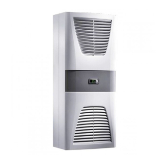
- Page 1 Enclosure cooling unit 3302.xxx 3328.xxx 3302.3xx 3329.xxx 3303.xxx 3332.xxx 3304.xxx 3361.xxx 3305.xxx 3366.xxx Assembly and operating instructions...
-
Page 2: Table Of Contents
4.6.4 Installing the power supply ........13 Finalising assembly ........15 4.7.1 Installing the filter media ........15 4.7.2 Fitting the cooling unit ......... 15 4.7.3 Setting the filter mat monitor (only with e-Comfort controller) ............16 Start-up .......... 16 Rittal enclosure cooling unit... -
Page 3: Notes On Documentation
Please observe the following general safety notes when CE labelling assembling and operating the unit: Rittal GmbH & Co. KG confirms the conformity of the – Assembly, installation and servicing may only be per- cooling unit with the European Union's Machinery Di- formed by properly trained specialists. -
Page 4: Device Description
Rear half of the enclosure from the enclosure air in the evaporator coil. The whole Louvred grille for air outlet cycle begins again. Display Infill panel Louvred grille for air inlet Rating plate Rittal enclosure cooling unit... -
Page 5: Control
PTC thermal component and is evaporated (through-flow heater principle). The water vapour Rittal enclosure cooling units are fitted with a controller streams out of the cooling unit with the airflow from the for setting the functions of the cooling unit. -
Page 6: Contents
– Check the packaging carefully for signs of damage. Traces of oil on damaged packaging are an indication Rittal GmbH & Co. KG is not liable for any damage which of refrigerant loss and leakages. Any packaging dam- may result from failure to comply with the documenta- age may be the cause of a subsequent functional fail- tion provided. -
Page 7: Layout Of The Electronic Components In The Enclosure
(2) or fully internally mounted (3): Fig. 4: Never direct the cold airflow at active components Air diversion components are available as accessories – please refer to the Rittal Catalogue. Fig. 6: Installation method It is important to ensure even air circulation inside the en- To this end, cut the side panel or door of the enclosure closure. -
Page 8: Making The Cut-Outs
Fig. 8: Securing the cooling unit (all models except 3302.1xx) Loosen the flat-pin connectors of the PE conductor between the two enclosure halves. Disconnect the fan connection. Remove the front enclosure tray completely. Rittal enclosure cooling unit... -
Page 9: Full Internal Mounting Of The Cooling Unit
4.3.4 Full internal mounting of the cooling unit Carefully remove the louvred grille and the infill panel from the enclosure by pulling forwards. Carefully disconnect the connector from the rear of the display. Rittal enclosure cooling unit... -
Page 10: Connecting The Condensate Discharge
– must be laid with a suitable and constant gradient (no siphoning) – must be laid without kinks – must not have a reduced cross-section if extended The condensate hose is available as an accessory (refer also to Accessories in the Rittal Catalogue). Rittal enclosure cooling unit... -
Page 11: Notes On Electrical Installation
– The fans and compressors in single- and three-phase connected impedance or consult the responsible elec- units are intrinsically safe (thermal winding protection). tricity supply company. If there is no way of influencing This also applies to transformer versions, types Rittal enclosure cooling unit... -
Page 12: Potential Equalisation
X3. This is used to evaluate system messages in a PLC, for remotely setting parameters and monitor- ing, or for integration into the facility management sys- tem. 4.6.3 Mounting external transformer Only for 3361.x40. Rittal enclosure cooling unit... -
Page 13: Installing The Power Supply
Serial interface (Model No. 3124.200) Serial interface Sub-D, 9-pole Serial interface cable Sub-D connector, 9-pole Master-slave bus cable (Model No. 3124.100) Bu. Sub-D jack, 9-pole RTT Rittal TopTherm cooling units Adr. Address Supply connection/door limit switch/alarms Adr.: 06 Adr.: 11 Adr.: 12 Adr.: 13... - Page 14 4 Assembly and connection 3302.100/.110, 3302.300/.310 Fig. 23: Electrical wiring plan no. 1 3303.500/.510, 3303.600/.610, 3361.500/.510, 3361.600/.610, 3361.540/.640 3304.500/.510/.504/.514/.520/.600/.610 3305.500/.510/.504/.514/.520, 3328.500/.510/.504/.514/.520, 3329.500/.510/.504/.514/.520, 3305.600/.610, 3328.600/.610, 3329.600/.610, 3366.500/.510/.600/.610 Fig. 24: Electrical wiring plan no. 2 Rittal enclosure cooling unit...
-
Page 15: Finalising Assembly
PU foam filter mat (avail- able as an accessory) in the cooling unit. For air contain- ing oil condensate, we recommend the use of metal fil- ters (also available as an accessory). When used in Rittal enclosure cooling unit... -
Page 16: Setting The Filter Mat Monitor (Only With E-Comfort Controller)
If the cooling unit and compressor run times are too closure temperature will then appear in the 7-segment long < 1 minute, the switching hysteresis to protect display the cooling unit is automatically increased. – Floating system message contact in case of overtem- perature Rittal enclosure cooling unit... -
Page 17: Operating And Error Display
(sys- The NC and NO definitions refer to the de-energised tem message relay with changeover contact, see con- state. As soon as power is applied to the cooling unit, Rittal enclosure cooling unit... -
Page 18: Test Mode With The Basic Controller
In normal operation, the green LED is permanently illumi- unit (degrees Celsius) nated. Set button Next, rotate the potentiometer back to the required Programming button, also display of the set temperature setpoint. unit (degrees Fahrenheit) 7-segment display Rittal enclosure cooling unit... -
Page 19: Properties
Properties 6.2.2 Eco mode – Rated operating voltage: All Rittal TopTherm cooling units with e-Comfort control- ler from firmware 3.2 have the energy-saving eco mode, – 115 V or which is enabled in the delivered state. – 230 V or The eco mode is used to save energy in the heat ex- –... -
Page 20: General Information About Programming
"22". Keep the programming button (°C) held down until "22" appears. Press button 2 ("Set") to confirm the code. You can now alter the parameter within the preset limits. Rittal enclosure cooling unit... -
Page 21: Editable Parameters
Eco mode OFF: 0 / Eco mode ON: 1 tion Changing the au- This parameter allows you to change the "22" thorisation code authorisation code (factory setting). The new code results from the sum of 22 + PSO. Tab. 4: Editable parameters Rittal enclosure cooling unit... -
Page 22: Programming Overview
6 Operation 6.2.6 Programming overview Fig. 32: Programming overview Rittal enclosure cooling unit... -
Page 23: Defining System Messages For Evaluation
System message is evaluated by relay 2 This is the normal operating state of the cooling unit. As soon as a system message occurs or the power supply is interrupted, the corresponding relay will drop out and open the contact. Rittal enclosure cooling unit... -
Page 24: Setting The Master/Slave Identifier
Set the enclosure interior temperature to a ard. higher value. Check the evaporator fan; Evaporator coil fan may be mechani- release or exchange if necessary. cally blocked, defective, or cold air out- let obstructed. Tab. 6: Troubleshooting with the e-Comfort controller Rittal enclosure cooling unit... - Page 25 1 and confirm with "Set" until "Acc" appears. Next, disconnect the unit from the mains and reconnect. LAN/Master-Slave Master and slave not connected Check setting and/or cable Tab. 6: Troubleshooting with the e-Comfort controller Rittal enclosure cooling unit...
-
Page 26: Reset The E-Comfort Controller
Any stubborn, oily stains may be removed using a non-flammable de- tergent, such as degreaser. Rittal enclosure cooling unit... - Page 27 7 Inspection and maintenance Fig. 35: Remove the top louvred grille Fig. 37: Remove the infill panel Fig. 36: Remove the bottom louvred grille Fig. 38: Disconnect the connector from the display (1) Rittal enclosure cooling unit...
- Page 28 Disconnect the fan connectors Fig. 40: Cooling unit without grille Fig. 44: Remove the cover (undo the four nuts) Fig. 41: Remove the external circuit fan (undo four screws) Fig. 45: Slide the display cable back Rittal enclosure cooling unit...
- Page 29 Remove the cover (2) Fig. 49: Release the earthing cable between the cover and the Fig. 47: Remove the cover (1) chassis (1) Fig. 50: Release the earthing cable between the cover and the chassis (2) Rittal enclosure cooling unit...
-
Page 30: Compressed Air Cleaning 3328.Xxx
Clean the heat exchanger coil and compressor cham- ber using compressed air (1) Fig. 54: Remove the top louvred grille (1) Fig. 52: Clean the heat exchanger coil and compressor cham- ber using compressed air (2) Rittal enclosure cooling unit... - Page 31 7 Inspection and maintenance Fig. 55: Remove the top louvred grille (2) Fig. 57: Remove the bottom louvred grille (1) Fig. 56: Remove the top louvred grille (3) Fig. 58: Remove the bottom louvred grille (2) Rittal enclosure cooling unit...
- Page 32 Fig. 60: Disconnect the display cable Fig. 64: Remove the external circuit fan Fig. 61: Slide the display cable back and push it through the ca- ble gland (1) Fig. 65: Disconnect the fan connectors (1) Rittal enclosure cooling unit...
- Page 33 Fig. 70: Undo the four screws for the cover Fig. 67: Disconnect the fan connectors (3) Fig. 68: Disconnect the fan earthing cable (1) Fig. 71: Removing the cover Fig. 69: Disconnect the fan earthing cable (2) Rittal enclosure cooling unit...
- Page 34 Fig. 74: Clean the heat exchanger coil and compressor cham- ber using compressed air (1) Fig. 73: Disconnect the earthing cable (2) Fig. 75: Clean the heat exchanger coil and compressor cham- ber using compressed air (2) Rittal enclosure cooling unit...
-
Page 35: Installation Instructions For Nema 4X Devices
Cover Fig. 79: Remove the cover (1) Cooling unit Turn in bolt Loosen wing nuts Affix sealing tape Fig. 77: Preparation Disconnect PE conductor Fig. 80: Remove the cover (2) Rittal enclosure cooling unit... -
Page 36: Storage And Disposal
Store the cooling unit in the appropriate position for transport. The closed cooling cycle contains refrigerant and oil, which must be properly disposed of for the protection of the environment. Facilities for disposal are available at the Rittal plant. Please contact us for advice. Rittal enclosure cooling unit... - Page 37 – External circuit – IP 34 UL-Type rating – Dimensions (W x H x D) 280 x 550 x 140 525 x 340 x 153 280 x 550 x 210 400 x 950 x 260 Weight Rittal enclosure cooling unit...
- Page 38 ≤ 64 ≤ 69 Protection category to IEC 60 529 – Internal circuit – IP 54 – External circuit – IP 34 UL-Type rating – Dimensions (W x H x D) 400 x 950 x 260 Weight Rittal enclosure cooling unit...
- Page 39 ≤ 68 ≤ 69 Protection category to IEC 60 529 – Internal circuit – IP 54 – External circuit – IP 34 UL-Type rating – Dimensions (W x H x D) 400 x 1580 x 295 Weight Rittal enclosure cooling unit...
- Page 40 – Internal circuit – IP 54 – External circuit – IP 34 UL-Type rating – Dimensions (W x H x D) 400 x 1580 x 295 500 x 1580 x 280 x 550 x 280 Weight Rittal enclosure cooling unit...
- Page 41 Protection category to IEC 60 529 – Internal circuit – IP 54 – External circuit – IP 34 UL-Type rating – Dimensions (W x H x D) 3366: 435 x 1590 x 204 / 3377: 435 x 1590 x 165 Weight Rittal enclosure cooling unit...
- Page 42 Protection category to IEC 60 529 – Internal circuit – IP 55 – External circuit – IP 34 UL-Type rating – Dimensions (W x H x D) 285 x 520 x 298 405 x 1020 x 358 Weight Rittal enclosure cooling unit...
-
Page 43: Performance Diagrams
IP 55 – External circuit – IP 34 UL-Type rating – Dimensions (W x H x D) 405 x 1650 x 388 Weight Performance diagrams The performance diagrams can be found on the Rittal homepage: http://www.rittal.com/imf/none/3_5132/Rittal_3303500_Kennlinienfelder_3_5132 Rittal enclosure cooling unit... -
Page 44: List Of Spare Parts
10 List of spare parts List of spare parts 3302.xxx Fig. 84: Spare parts for 3302.xxx 3302.3xx Fig. 85: Spare parts for 3302.3xx Rittal enclosure cooling unit... - Page 45 10 List of spare parts 3303.xxx 3361.xxx Fig. 86: Spare parts for 3303.xxx, 3361.xxx 3304.xxx 3305.xxx Fig. 87: Spare parts for 3304.xxx, 3305.xxx Rittal enclosure cooling unit...
- Page 46 10 List of spare parts 3328.xxx 3329.xxx Fig. 88: Spare parts for 3328.xxx, 3329.xxx 3332.xxx Fig. 89: Spare parts for 3332.xxx Rittal enclosure cooling unit...
-
Page 47: Appendix
As well as the spare part number, when or- dering spare parts the following information must be provided: – Unit model – Fabrication number – Date of manufacture This information may be found on the rating plate. Rittal enclosure cooling unit... - Page 48 4X devices) Ø 8 (4x) Fig. 93: 3303.xxx, 3361.xxx external mounting (except NEMA 4X devices) Ø 13 (10x) Fig. 96: 3328.xxx, 3329.xxx external mounting (except NEMA 4X devices) Ø 8 (10x) Fig. 94: 3366.xxx external mounting Rittal enclosure cooling unit...
- Page 49 11 Appendix Ø 13 (10x) 9.5 (8x) Fig. 97: 3332.xxx external mounting Fig. 99: 3304-5.5x4 13 (10x) 8 (8x) Fig. 98: 3303.xx4 Fig. 100: 3328-29.5x4 Rittal enclosure cooling unit...
-
Page 50: Dimensions For Partial Internal Mounting
Ø 13 (4x) R9.5 (2x) Fig. 103: 3328.xxx, 3329.xxx partial internal mounting 25 x 45º 20 x 45º Ø9,5 (4x) Fig. 102: 3304.xxx, 3305.xxx partial internal mounting Ø 13 (4x) Fig. 104: 3332.xxx partial internal mounting Rittal enclosure cooling unit... -
Page 51: Dimensions For Full Internal Mounting
Fig. 106: 3302.3xx full internal mounting (3303.xxx) (3361.xxx) Ø 13 (4x) Ø 19 (2x) R9.5 (2x) Fig. 109: 3328.xxx, 3329.xxx full internal mounting 18 x 45˚ Ø 8 (4x) (230) Fig. 107: 3303.xxx, 3361.xxx full internal mounting Rittal enclosure cooling unit... -
Page 52: Electrical Wiring Plan
11.2 Electrical wiring plan 3302.100/.110, 3302.300/.310 Mains X1 L1 1 2 3 NTC I red NTC E blue Power Term 1 2 3 1 2 3 1 2 3 Fig. 111: Electrical wiring plan no. 1 Rittal enclosure cooling unit... - Page 53 1 2 3 NTC I red Serial NTC E blue Power NTC C white NTC A yellow Level green Term 1 2 3 1 2 3 1 2 3 Fig. 113: Electrical wiring plan no. 3 Rittal enclosure cooling unit...
- Page 54 1 2 3 NTC I red Serial NTC E blue Power NTC C white NTC A yellow Level green Term 1 2 3 1 2 3 1 2 3 Fig. 115: Electrical wiring plan no. 5 Rittal enclosure cooling unit...
- Page 55 Fig. 116: Electrical wiring plan no. 6 3366.500/.510/.600/.610 Mains L2/N 1 2 3 Serial NTC I red NTC E blue Power NTC C white NTC A yellow Level green Term 1 2 3 C1.2 C1.1 Fig. 117: Electrical wiring plan no. 7 Rittal enclosure cooling unit...
- Page 56 LED operational green LED alarm red Compressor Condenser fan Evaporator fan Potentiometer for setting the temperature Door limit switch (without door limit switch: ter- minal 1, 2 open) Transformer (optional) Main terminal strip Master/slave connection Optional interface Rittal enclosure cooling unit...
- Page 58 ◾ Climate Control ◾ IT Infrastructure ◾ Software & Services You can find the contact details of all Rittal companies throughout the world here. www.rittal.com/contact RITTAL GmbH & Co. KG Postfach 1662 · D-35726 Herborn Phone +49(0)2772 505-0 · Fax +49(0)2772 505-2319...
Need help?
Do you have a question about the 3302 Series and is the answer not in the manual?
Questions and answers